Advertisement
Table of Contents
- 1 Parts Included
- 2 Parts Required but Not Included
- 3 Atomic Transmission Control Module Installation
- 4 Wiring
- 5 Atomic TCM Handheld Menu
- 6 Initial Setup
- 7 Advanced Setup
- 8 TCM Dash and Gauge Parameters
- 9 Operational Notes and Safeguards
- 10 Gear Transition Vehicle Speed (MPH)
- 11 Diagnostics
- 12 Clearing Diagnostic Errors
- 13 Limited Warranty
- Download this manual
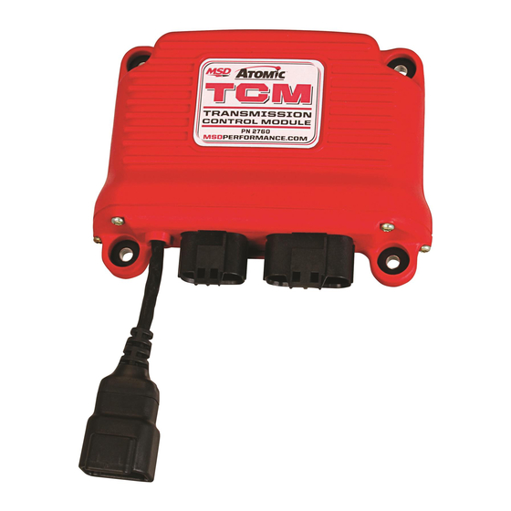
MSD Atomic Transmission Control Module
ONLINE PRODUCT REGISTRATION: Register your MSD product online. Registering your product
will help if there is ever a warranty issue with your product and helps the MSD R&D team create
new products that you ask for! Go to www.msdperformance.com/registration.
Thank you for purchasing the MSD Atomic Transmission Control Module (TCM). MSD is pleased
to announce that this transmission controller was designed with performance reliability, practicality,
and ease of use in mind. Using the correct adapter harness, this unit will plug directly into the factory
connectors on 4L60E/4L70E/4L80E GM transmissions, or the Ford AODE, 4R70W/E, 4R75W/E, E4OD,
and 4R100 transmissions. The Atomic TCM was designed to work as a stand-alone transmission
controller. Programming the transmission controller is done through the handheld monitor, which
eliminates the need for a computer to program the transmission controller.
As with any performance product, please be sure to read the entire instruction manual before
attempting to install this system on your vehicle. Please contract our customer support department
at (915) 855-7123 if you have any question about installing or operating the transmission controller.
Parts Included:
1 - AtomicTransmission Control Module
1 - Handheld monitor
1 - 4G Micro SD Card
ATOMIC TRANSMISSION CONTROL MODULE INSTALLATION
It is important to select a proper mounting location for the
TCM. The unit can be mounted in the interior or the engine
compartment as long as it is away from direct heat sources.
It is not recommended to mount the unit in an enclosed
area, such as the glove box. When a suitable location is
found, make sure all wires reach their connections. Use the
TCM as a template and mark the location of the holes. Use
a size #20 drill bit to prepare for the supplied self tapping
screws. Assemble the sleeves in the TCM (Figure 1).
Note: Mounting this module near headers or high heat
sources may affect the operation of the TCM.
M S D
• W W W . M S D P E R F O R M A N C E . C O M • ( 9 1 5 ) 8 5 5 - 7 1 2 3 • F A X ( 9 1 5 ) 8 5 7 - 3 3 4 4
PN 2760
Parts required but not included:
Transmission Harnesses
(only transmission specific harness is needed)
PN 2770 - 4L6XE (1992+) / 4L7XE (2006-on) / 4L8XE
(1993+) harness
PN 2771 - 4L7XE (2009+) harness
PN 2772 - Ford 4R7XW/E (1998+) harness
PN 2773 - Ford AODE/4R70W/E (1992-1997) harness
PN 2774 - Ford 4R100 (1998+) harness
PN 2775 - Ford E4OD (1995-1997) harness
PN 2776 - Ford E4OD (1989-1994) harness
Figure 1
Advertisement
Table of Contents

Related Manuals for MSD 2760


Summary of Contents for MSD 2760
- Page 1 PN 2760 ONLINE PRODUCT REGISTRATION: Register your MSD product online. Registering your product will help if there is ever a warranty issue with your product and helps the MSD R&D team create new products that you ask for! Go to www.msdperformance.com/registration.
- Page 2 INSTALLATION INSTRUCTIONS WIRING Color Function Brown Ground White Signal Brown Overdrive Cancel (Ford Applications Only) Black TPS Ground Reference Gray Calibration Select Dark Blue Manual Bump up / Manual Mode Select Green TCC Lock Speed Out TCC Unlock Orange TPS 5V Lt.
- Page 3 DOWNSHIFT. PINK (12V IGNITION IN): Connect to switched ignition 12v source. WHITE (RPM/TACH IN): Connect to tach output on MSD Ignition or coil (-) on inductive ignition. Note: Will accept 5V(+) used to trigger GM LS coil packs. YELLOW (TPS SIGNAL IN): Connect to TPS sensor signal.
- Page 4 INSTALLATION INSTRUCTIONS BACKLIGHT LEVEL: Adjust the brightness of the screen. The brightness can be adjusted up or down using the joystick in five percent increments (Figure 4). DISPLAY UNITS: Display items in either English (inches, Fahrenheit, MPH) or Metric (mm, Celsius, KPH) (Figure 4). USER MODE: Used for changing parameters in Atomic LS EFI systems.
-
Page 5: Initial Setup
INSTALLATION INSTRUCTIONS ATOMIC TCM HANDHELD MENU TCM DASH: Eleven parameters are displayed in real-time: CAL SELECT, ENGINE RPM, SPEED, TPS, FLUID TEMP , PCS DUTY CYCLE , SHIFT POS., GEAR, TCC LOCKED, SHIFT MODE, and DTC COUNT (Figure 5). Refer to the table labeled TCM DASH for a complete description of each parameter in the Atomic Dash (Figure 5). - Page 6 INSTALLATION INSTRUCTIONS TRANSFER RATIO: Selection menu for transfer case gear ratio. Adjustable from 0.50 to 10.00 in 0.01 increments. Leave this value set to the default (1.00) unless the vehicle is equipped with a transfer case. NOTE: Changes made in this menu selection only apply to Calibration B (grey activation wire) (Figure 7).
- Page 7 INSTALLATION INSTRUCTIONS ADVANCED SETUP Note: Changes to Calibration A and Calibration B parameters (SHIFT MULTIPLIER, TCC MULTIPLIER, and FIRMNESS MULTIPLIER) take effect in real time and do not require power cycling of the Atomic TCM in order to be committed to memory.
- Page 8 INSTALLATION INSTRUCTIONS WOT THRESHOLD: (Wide Open Throttle) The Atomic TCM module utilizes a MPH/KPH shifting strategy. When the throttle position exceeds the WOT Threshold setting, the TCM will switch to an RPM shifting strategy, and will upshift automatically when the ENGINE RPM reaches the MAX SHIFT RPM (set in the Initial Setup menu).
- Page 9 “NO” to “YES” using the joystick on the hand held. Then press down on the joystick in the center. This setting is useful for installing the transmission control module on another transmission or for troubleshooting. Note: MSD recommends loading the Atomic TCM defaults after performing a software update. TCM DASH AND GAUGE PARAMETERS (FIGURE 12) Engine RPM...
- Page 10 RPM to be exceeded. Figure 13 MSD 2760 – Atomic Transmission Controller – Diagnostics Summary M S D • W W W . M S D P E R F O R M A N C E . C O M • ( 9 1 5 ) 8 5 5 - 7 1 2 3 • F A X ( 9 1 5 ) 8 5 7 - 3 3 4 4...
- Page 11 This code will set if an internal problem prevents EEPROM problem with its internal Electronically interrogation when the unit is powered on. Return the unit Erasable Programmable Read-Only to MSD for testing or replacement. Memory (EEPROM). SYS VOLT LO The controller has detected a system Ensure that the battery is fully charged, the alternator is voltage below 10.5 VDC for more...
-
Page 12: Limited Warranty
*Intended normal use means that this item is being used as was originally intended and for the original application as sold by MSD. Any modifications to this item or if it is used on an application other than what MSD markets the product, the warranty will be void.
Need help?
Do you have a question about the 2760 and is the answer not in the manual?
Questions and answers