JUMO dTRANS p20 Operating Instructions Manual
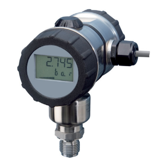
Process pressure transmitter
Hide thumbs
Also See for dTRANS p20:
- Operating manual (88 pages) ,
- Operating instructions manual (60 pages) ,
- Operating manual (84 pages)

Related Manuals for JUMO dTRANS p20


Summary of Contents for JUMO dTRANS p20
- Page 1 JUMO dTRANS p20 Process pressure transmitter B 403025.0 Operating Instructions 2014-03-18/00525980...
- Page 2 DANGER! Failure of the pressure transmitter or an instrument attached to it could possibly lead to dangerous malfunctions! Suitable preventive measures must be in place to prevent this from happening. NOTE! Please read these Operating Instructions before placing the instrument in operation. Keep the Operating Instructions in a place which is accessible to all users at all times.
-
Page 3: Table Of Contents
Contents Safety information ............... 5 Warning signs ..................5 Reference signs ................... 5 General information ............. 7 Scope of application ................7 Scope of delivery ................. 8 Instrument identification ........... 11 Nameplate ..................11 Order details ..................13 Accessories ..................15 Software .................... - Page 4 Contents Assembly in the explosion area ............34 Installation ................35 Installation instructions ..............35 Instrument with cable gland .............. 36 Instrument with M12 connector ............39 Electrical connection in Ex areas ............41 Operation ................45 Display ....................45 Operation with rotary knob or with setup program ......
-
Page 5: Safety Information
1 Safety information Warning symbols DANGER! This symbol indicates that personal injury caused by electrical shock may occur if the respective precautionary measures are not carried out. CAUTION! This symbol in connection with the signal word indicates that damage to assets or data loss will occur if the respective precautionary measures are not taken. - Page 6 1 Safety information...
-
Page 7: General Information
Scope of application General information The JUMO dTRANS p20 pressure transmitter measures the pressure of non-corrosive and corrosive gases, vapors and liquids. The output signal is an impressed DC current (4 to 20 mA) which is proportional to the input pressure. -
Page 8: Scope Of Delivery
If the calibration certificate is lost, or if you need another copy, it can be ordered from JUMO. Please indicate the F number of the pressure transmitter (manufacturing number, see the nameplate). - Page 9 2 General information ® HART modem ® Available as an accessory: HART modem for USB, part no. 00443447. ® ® The HART modem can be used to connect the pressure transmitter with the USB interface ® of a PC via the HART interface.
- Page 10 2 General information...
-
Page 11: Instrument Identification
3 Instrument identification Nameplate Non-Ex, Enclosure Identification on the enclosure of a pressure transmitter that is not suitable for use in hazardous (Ex) areas. Type Part number Factory setting Nominal measuring range for measurement range Voltage supply Output signal Manufacturing number Date of manufacture The date of manufacture (year and calendar week) of the instrument is encoded in the manufacturing number. - Page 12 3 Instrument identification Ex, Enclosure 1 First identification on the enclosure of a pressure transmitter that is suitable for use in hazardous (Ex) areas. Made in Germany www.jumo.net dTRANS p20 403025/x-1 TN 12345678 CAL 0...10 bar rel -1...25 bar DC 11.5...28 V 4...20 mA HART...
-
Page 13: Order Details
3 Instrument identification Order details (1) Basic type 403025 dTRANS p20 - Process pressure transmitter (2) Basic type extension None Special design (3) Explosion protection None ATEX Ex ia (4) Housing Short, stainless steel, with M12 connection Long, stainless steel, with cable gland... - Page 14 Taper connection with union nut DN 40 to DIN 11851 (milk cone) Clamp DN 25 to DIN 32676 Clamp DN 50 to DIN 32676/2" ISO 2852 JUMO PEKA with EHEDG approval Suitable for connecting to a diaphragm seal (12) Temperature of medium Up to 120 °C...
-
Page 15: Accessories
Pressure separator with flange connection to ANSI B 16.5 with sealing lip Form RF 409786 Ex-i Power supply/input isolating amplifier 707530 The PC interface cable is the connection between the JUMO interface of the pressure transmitter and the USB interface of a PC. ® The HART modem is the connection between the HART®... -
Page 16: Dimensions
3 Instrument identification Dimensions Type 403025/0-0-1 (short, stainless steel, with M12 connection) 86.5 Type 403025/0-0-2 (long, stainless steel, with cable gland) A = Cable gland M20 × 1.5... - Page 17 3 Instrument identification Type 403025/0-0-3 (long, precision casting, with cable gland) A = Cable gland M20 × 1.5...
-
Page 18: Dimensions For Medium Temperature
3 Instrument identification Dimensions for medium temperature 2 (high-temperature versions) In pressure transmitters suitable for medium temperatures up to 200 °C (medium temperature 2), the increased temperature is dissipated over an extended shaft. The overall height of all the pressure transmitters in this version increases as in the diagram below, by 41 mm. -
Page 19: Dimensions Of Process Connections
(G 3/4) (tapered adapter with groove union nut to DIN 11851) SW 32 G 3/4 613 und 616 (Clamp to DIN 32676) (JUMO PEKA) SW 27 Dimensions of process connections 604, 606, 613 and 616 Conn. Ø 44 Ø 35 Rd 52 ×... - Page 20 3 Instrument identification...
-
Page 21: Technical Data
For output 410 (4 to 20 mA with HART®) JUMO interface and HART interface The JUMO interface must not be used for instruments with ATEX Ex ia explosion protection! These instruments ® can be operated by the rotary knob or via the HART interface. -
Page 22: Input
4 Technical data Input Relative pressure Nominal measuring -600 to +600 mbar -1 to +4 bar -1 to +25 bar -1 to +100 bar -1 to +600 bar range rel. rel. rel. rel. rel. Overload capacity 6 bar 30 bar 150 bar 300 bar 1200 bar... -
Page 23: Mechanical Properties
Process seal For process connection 512 and 571 For process connection 652 For process connection 997 FDA-compliant, EHEDG approved materials: FPM, VMQ, (JUMO PEKA) EPDM option, see data sheet 409711 For all other process connections Without a seal Measuring membrane For material 20 1.4542 at measuring range 516... -
Page 24: Ambient Conditions
Restricted function below -20 °C: stationary use, increased danger of broken cable, display does not function. In the range of -40 to -50°C, the cover with the instrument viewing pane must also be protected against mechanical shock and impact. For details please contact JUMO. Only for high temperature version (temperature of medium 2). -
Page 25: Accuracy
4 Technical data Accuracy Relative pressure Nominal -600 to +600 mbar -1 to +4 bar -1 to +25 bar -1 to +100 bar -1 to +600 bar measuring range rel. rel. rel. rel. rel. Factory setting for 0 to 600 mbar 0 to 4 bar 0 to 25 bar 0 to 100 bar 0 to 600 bar... -
Page 26: Approvals/Marks Of Conformity
SEV 09 ATEX 0138 X EN 60079-0 403025/x-1-... EN 60079-11 EN 60079-26 EHEDG TUM MAK 03/2006 Document No.8 Process connection 997 (JUMO PEKA) INMETRO CEPEL CEPEL 13.2213X IEC 60079 Extra code 227 Det Norske A-13300 Testing report 203951/4 403025/x-1-.../880 Veritas AS... -
Page 27: Mounting
The permissible ambient temperature must be maintained (not any possible heat radiation). The JUMO dTRANS p20 pressure transmitter can be installed above or under the pressure tapping point. Unscrew the front ring or housing cover Plastic cover ring The front ring (1) and rear housing cover (2) can be unscrewed. -
Page 28: Rotating The Lcd (Display)
Rotating the LCD (display) Installation position The nominal position of the JUMO dTRANS p20 pressure transmitter is standing and vertical. Depending on the specific features of the measuring point, the pressure transmitter can be installed in any other location. The LCD display can be rotated in 90° increments to reach the... -
Page 29: Rotating The Enclosure
5 Mounting Unscrew the front ring, see chapter 5.2 "Unscrew the front ring or housing cover", page Pry out the electronics module with a narrow (small screwdriver). Rotate the electronics module to the preferred position (in 90° increments) and reinsert it. Screw on the front ring finger-tight. -
Page 30: Pressure Connection
5 Mounting Pressure connection Gaskets Operating conditions (for example material compatibility) must be considered when selecting the seal. Tightening torques Maximum 200 Nm. The correct tightening torque depends on the size, material and shape of the seal that is used and the pressure connection of the pressure transmitter. -
Page 31: Measuring The Relative Or Absolute Pressure
5 Mounting Measuring the relative or absolute pressure Gases Transmitter above Transmitter below the pressure tapping point (normal arrangement) the pressure tapping point (exception) Transmitter Shut-off fitting 2A Shut-off valve for the process 2B Shut-off valve for the test connection Pressure line Shut-off valve Shut-off valve (optional) - Page 32 5 Mounting Vapor Transmitter Shut-off fitting 2A Shut-off valve for the process 2B Shut-off valve for the test connection Pressure line Shut-off valve Blow-out valve Level container Pressurization Starting position: All valves closed. Activate the shut-off fittings in the following order: Open the shut-off valve (4) on the pressure tapping support.
- Page 33 5 Mounting Liquids Transmitter Shut-off fitting 2A Shut-off valve for the process 2B Shut-off valve for the test connection Pressure line Shut-off valve Blow-out valve Pressurization Starting position: All valves closed. Activate the shut-off fittings in the following order: Open the shut-off valve (4) on the pressure tapping support. Open the shut-off valve (2A).
-
Page 34: Assembly In The Explosion Area
5 Mounting Assembly in the explosion area Hazardous (Ex) area Zone 0/20 Hazardous (Ex) area Zone 1/21 Non-hazardous area ® Burden (optional for HART interface). Voltage supply device with isolating converter for connecting explosion-protected transmitters... -
Page 35: Installation
6 Installation Installation instructions DANGER! The electrical connection must only be performed by qualified personnel! Ground the instrument! If contact with live parts is possible when working on the device, it must be completely dis- connected from the electrical supply. Electromagnetic compatibility meets the requirements of EN 61326. -
Page 36: Instrument With Cable Gland
6 Installation Instrument with cable gland General information DANGER! For connection to instruments in Ex areas see "Electrical connection in Ex areas", page 41! • Permissible cable diameter for instruments with cable gland made of: 6 to 12 mm • Max. wire cross-section 1.5mm ... - Page 37 6 Installation Connection Unscrew the housing cover from behind, see "Unscrew the front ring or housing cover", page 27. Ground the instrument! To connect the connecting cables, see the following illustration. Pin configuration Connection Pin configuration Voltage supply 1 L+ for non Ex version DC 11.5 to 36 V 2 L- for Ex version DC 11.5 to 28 V...
- Page 38 6 Installation Operation and test HART - HART + Test - Test + Total burden: Burden (U -11.5 V) ÷ 0.022 A; in addition: min. 250 , max. 1100 ® for HART Display or recording instrument, controller, PLC, etc. Voltage supply: For non Ex version DC 11.5 to 36 V For Ex version DC 11.5 to 28 V...
-
Page 39: Instrument With M12 Connector
6 Installation Instrument with M12 connector DANGER! For connection of the device in an Ex area see "Electrical connection in Ex areas", page 41! Connect the device to ground using pin 4 of the device connector see "Pin configuration", page 40! A suitable connection is provided by a •... - Page 40 6 Installation Pin configuration Connection Color configuration assignment Voltage supply 1 L+ Brown for non Ex version DC 11.5 to 36 V 3 L- Blue for Ex version DC 11.5 to 28 V Output Brown 4 to 20 mA two-wires Blue Impressed current 4 to 20 mA in voltage supply...
-
Page 41: Electrical Connection In Ex Areas
6 Installation Electrical connection in Ex areas General information Applicable requirements must be followed for the electrical connection, especially in a potentially explosive atmosphere: • Regulation concerning electrical systems in areas with an explosion hazard (Elex V) • Determination for project planning, selecting and setting up electrical systems in areas with an explosion hazard (IEC 60079-14:2007) •... - Page 42 DANGER! ® Only the HART modem may be used in explosion-protected areas! The JUMO interface must not be used! The power supply must be intrinsically safe and must not exceed the followingmaximum values: : DC 28 V : 93 mA...
- Page 43 6 Installation 6.4.1 Connection diagram "EX" (11) (10) Area with explosion hazard Zone 0/20 Hazardous (Ex) area Zone 1/21 Non-hazardous area (U ® Burden for HART -11.5 V) ÷ 0.022 A in addition min. 250 , max. 1100 The current limiting resistor integrated into the power supply device must be included in the calculations in this case.
- Page 44 6 Installation...
-
Page 45: Operation
7 Operation Display Socket for JUMO setup interface (behind a cap) Measurement value Unit of measure Overrange Output current (4 to 20 mA) Underrange... -
Page 46: Operation With Rotary Knob Or With Setup Program
The setup program can optionally access the instrument through the following interfaces: • JUMO setup interface. The PC interface cable with USB/TTL converter (USB connecting cable) is required to connect the PC with the instrument, part no. 00456352. -
Page 47: The Level Concept
7 Operation Rotate and press Rotate Select parameters or adjust values. Press Confirm parameters or values. The level concept Two levels Operation is on two levels: NOTE! After the instrument is turned on, it is on the display level. You can go to the parameter level through the following operation. - Page 48 7 Operation 7.3.1 The display level The measured pressure and other parameters are shown on the display level. The output current is shown as a percentage in a bar diagram on the third line. It is not possible to change parameters on the display level! Action Display Explanation...
- Page 49 7 Operation 7.3.2 The parameter level Instrument parameters can be displayed and changed on the parameter level. Action Display Explanation Selection (example) P min Reset by Saved minimum > 3 seconds pressure P max Reset by Saved maximum > 3 seconds pressure P0 Den 0.01 to 1.00 to 99.99...
- Page 50 7 Operation Action Display Explanation Selection (example) P7 Zero Current pressure Zero-point adjustment P8 mA 3.60 to 4.00 to 21.60 mA Current sensor P9 Err ErLo = 3.6 mA ErHi = 21.6 mA Current in case of error LASt = Last value P10 Key O = No lock LA = All, interface free...
- Page 51 7 Operation Action Display Explanation Selection (example) P18 SCD Auto = Automatic 0 = No places behind decimal point Scaling decimal point 1 = 1 place behind decimal point 2 = 2 places behind decimal point 3 = 3 places behind decimal point P19 % % (factory setting) kg/sec...
- Page 52 7 Operation...
-
Page 53: Maintenance
8 Maintenance Eliminating errors and faults Error/fault Possible cause Remedy Display: None No power supply Turn on the power supply Instrument faulty Send the instrument to the supplier for repairs Display: Overrange, Bring the pressure back into the overpressure measuring range or adjust the measuring range Display: Underrange,... - Page 54 8 Maintenance...
-
Page 55: Declaration Of Conformity
9 Declaration of Conformity... - Page 56 9 Declaration of Conformity...
-
Page 57: Type Examination Certificate
10 Type Examination Certificate... - Page 58 10 Type Examination Certificate...
- Page 59 10 Type Examination Certificate...
- Page 60 10 Type Examination Certificate...
- Page 61 10 Type Examination Certificate...
- Page 62 10 Type Examination Certificate...
- Page 64 JUMO GmbH & Co. KG JUMO Instrument Co. Ltd. JUMO Process Control, Inc. Street address: JUMO House 6733 Myers Road Moritz-Juchheim-Straße 1 Temple Bank, Riverway East Syracuse, NY 13057, USA 36039 Fulda, Germany Harlow - Essex CM20 2DY, UK Phone:...
Need help?
Do you have a question about the dTRANS p20 and is the answer not in the manual?
Questions and answers