Winland EnviroAlert EA800-ip Installation And Owner's Manual
Electronic multi-zone environmental alarm system
Hide thumbs
Also See for EnviroAlert EA800-ip:
- Quick start manual (2 pages) ,
- Quick start manual (4 pages)

Related Manuals for Winland EnviroAlert EA800-ip


Summary of Contents for Winland EnviroAlert EA800-ip
- Page 1 Electronic Multi-Zone Environmental Alarm System Installation/Owner’s Manual D-011-0152...
- Page 2 Limitations of the Alarm System or Device While your alarm system or device is reliable and sophisticated, it does not offer guaranteed protection against burglary, fire or other emergency. Any security product, whether commercial or residential, is subject to compromise or failure-to-warn for a variety of reasons. These include: Individuals may gain access through unprotected openings or have the technical sophistication to •...
-
Page 3: Table Of Contents
Table of Contents General Information..........................5 Overview ............................5 How to Use This Manual........................6 Block Diagrams..........................7 Symbols on the Product or Manual Labeling ..................8 Monitoring Screens ..........................9 Keys ..............................10 Console Connections........................11 Access Control and Passwords ....................... 13 System Configuration Parameters .................... - Page 4 Maintenance ............................41 Locking and Unlocking the EA800-ip ....................41 Pausing Monitoring and Cancelling Pause ..................42 Replacing a Sensor.......................... 43 Editing Sensor Parameters ......................44 Deleting a Sensor ..........................45 Changing the Date Format....................... 45 Changing the Time Format ......................46 Changing the Date or Time Setting....................
-
Page 5: General Information
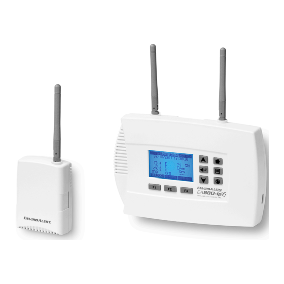
The EA800-ip console may be mounted directly to a standard 3-gang electrical enclosure or to walls. The wireless sensors are easily mounted to the wall. Figure 1 shows the console and a wireless sensor. Figure 1 EnviroAlert EA800-ip Console and Optional Wireless Sensor D-011-0152... -
Page 6: How To Use This Manual
How to Use This Manual How to Use This Manual This manual is organized into sections that guide you through the installation process, then describe how to use the EA800-ip and change its programmed settings if necessary. Some troubleshooting guidelines are provided. The manual presents EA800-ip programming procedures by showing you the sequence of menus and screens you will see as you perform the procedure, and the keys to press to advance to the next screen. -
Page 7: Block Diagrams
The EA800 can be made part of a larger security system as shown in Figure 3. In a security system there may be more than one EA800 installed along with other components such as the Winland EA200 or EA400 multi-zone environmental alarm systems. -
Page 8: Symbols On The Product Or Manual Labeling
Symbols on the Product or Manual Labeling Symbols on the Product or Manual Labeling Symbols appearing on the product labeling, packaging, and/or in this manual are shown and described in Table 1. Table 1 Symbols on Product or Manual Symbol Definition Attention, consult accompanying documents or statements. -
Page 9: Monitoring Screens
General Information Monitoring Screens The EA800-ip user interface is menu-based. During normal system monitoring, one of the following three screens is displayed depending on the current state of the programmed sensors: The MONITORING (home) screen is displayed when there are no active alarms. The screen lists all programmed sensors connected to the console and their current reading or state. -
Page 10: Keys
Keys Keys Figure 4 shows the console display and entry keys. The keys are described in Table 2. Figure 4 EA800-ip Console Keys Table 2 Key Functions Function This key's function changes as determined by the software. Its current function is displayed immediately above the key on the display. -
Page 11: Console Connections
General Information Table 2 Key Functions — continued MENU key: Displays the MAIN MENU screen when pressed from any menu level or from the home screen. SILENCE key: Alarms cannot be cleared and will continue to recur until the moni- tored conditions detected by the sensors are within the programmed parameters. - Page 12 Console Connections Table 3 EA800-ip Console Connector Functions Connector Designation Function USB Type A connection used to program firmware, export logs, and export and import configuration files. Power In 11-26 VDC input power connection for EA800-ip console (from accessory power supply or alarm panel).
-
Page 13: Access Control And Passwords
General Information Access Control and Passwords The EA800-ip console is normally locked to prevent unauthorized use. The currently active function of the F1 soft key (UNLOCK or LOCK) is displayed above the key. The locked and unlocked states are described below. Note: The console locks automatically after 30 minutes of inactivity if the user does not press the LOCK soft key (F1). - Page 14 System Configuration Parameters Table 4 System Configuration Parameters — continued Buzzer • Enable Enabled Enables and disables the buzzer when an alarm limit has been exceeded or a warning condition exists. • Disable WARNING Selecting Disable for this parameter turns the audible alarm buzzer off completely.
-
Page 15: Sensors
General Information Sensors A variety of sensors may be used with the EA800-ip console to provide environmental status and information. These include the following: Wired Sensors: Outputs 1 through 4 are for use with sensors wired to the console. Wired sensors can be any ■... -
Page 16: Humidity Sensors
Sensors Table 5 EA800-ip Compatible Temperature Sensors — continued TEMP-UL-S Thermistor stainless steel probe, -148° F to 32° F ultra low temperature sensor (-100° C to 0° C) EA-WTS Stand alone wireless temperature 32° F to 122° F sensor. NOT for use in coolers or (0°... -
Page 17: Power Supply / Sensor Voltage Selection
General Information EA800 If Vsensor > 8 V and Aux Power = 12V Note: Wiring shown inside this box is internal to EA800. No additional wiring is required. External 4-20 mA Supply Aux Power Transmitter Max load of 200 ohms includes 1000 ft. -
Page 18: Water Sensors
Sensors Power Supplied to EA800-ip (max.) [Maximum Power Supplied to EA800-ip or (max.) [Maximum sensor sensor or AUX. Power Out sensor voltage rating] AUX. Power Out sensor voltage rating] 14 VDC 10 VDC 22 VDC 18 VDC 15 VDC 11 VDC 23 VDC 19 VDC 16 VDC... -
Page 19: Sensor Parameter Descriptions
General Information Sensor Parameter Descriptions This section provides a description of each sensor parameter. Table 11 Sensor Parameter Descriptions Parameter Applicable to Sensors Description Sensor Name All A name used to identify the sensor in the alarm system. Select a name readily identified by the viewer. - Page 20 Sensors Table 11 Sensor Parameter Descriptions — continued Parameter Applicable to Sensors Description Low Alarm • Blue, Red and White The Low Alarm Limit sets the value that trips the low alarm when Limit temperature sensors exceeded. • HA-III+ • 4-20mA sensor •...
-
Page 21: Relay Operation
General Information Relay Operation This section describes the operation of the console's relays. The relays must be programmed correctly so that their outputs provide the desired signaling to the alarm panel. Table 12 Relay Configuration Settings Relay Setting Description No Alarm No Alarm: Power is removed from the relay coil as shown at N.C. -
Page 22: Installation
Installation Tools and Supplies Required Ensure that you have the following prior to starting the installation: Phillips screwdriver ■ Mounting hardware for the EA800-ip console and any optional sensor units ■ If required, a drill and the appropriate drill bits ■... -
Page 23: Install The Wired Sensors
Installation Mount the mounting plate as follows: Mounting to 3-gang enclosure: Use four (4) machine screws to secure the mounting plate to the mating holes ■ in the 3-gang enclosure. Mounting to drywall surface: Place the mounting plate in mounting position. Mark the four mounting hole ■... - Page 24 Install the Wireless Sensors Note: Verify that the wireless sensors can communicate with the console as outlined in the following procedure before permanently mounting them. Remove the cover from the wireless sensors and record the MAC addresses (see Figure 8) of each wireless sensor.
-
Page 25: Connecting Wired Sensors
Installation When a sensor is detected, confirm that the ID ■ number shown matches the ID number on the sensor’s label. If the sensors can communicate with the EA800-ip, ■ their IDs appear in the list as shown in the example at right. - Page 26 Connecting Wired Sensors After connecting the wire ends to the terminal block, align the terminal block to the correct header pins, and press it fully onto the header connector pins. External Adapter-Powered Console-Powered EA800 Console EA800 Console External Power Input N Aux Power Out Input N Aux Power Out...
-
Page 27: Programming
Installation 4-20mA Sensors 4-20mA Sensors 4-20mA Sensors (3-wire) (2-wire) (4-wire) EA800 Console EA800 Console EA800 Console Input N Aux Power Out Input N Input N Aux Power Out Aux Power Out User User User supplied supplied supplied cable cable cable EA800-ip 4-20mA Console... -
Page 28: Accessing The Main Menu For Programming
Accessing the MAIN MENU for Programming If not already powered up, apply power to the EA800-ip console. During the boot process: The Winland Electronics splash screen is displayed. ■ The system verifies flash memory, as indicated by FLASH BOOT at the bottom of the screen. -
Page 29: Adding Wireless Sensors
Installation Adding Wireless Sensors Unlock the console if necessary to continue programming. See “Accessing the MAIN MENU for Programming” on page 28. Select SENSORS from the MAIN MENU and follow the steps in the following diagram. After you press the ENTER key, the NEW WIRELESS SENSOR screen is displayed. The EA800-ip searches for new wireless sensors, indicated by an arrow that moves from left to right across the screen. - Page 30 Adding Wireless Sensors Example shown, set values as appropriate for your system. Note: Repeat this section for each wireless sensor you need to program. The programming options may differ slightly, depending on the type of wireless sensor being programmed. D-011-0152...
-
Page 31: Verify Wireless Signal Strength
Installation Verify Wireless Signal Strength After temporarily mounting the wireless sensors in the desired location, verify the signal strength at the console by performing the following procedure to verify the signal strength of each programmed wireless sensor. It may take as long as 30 seconds to acquire the current signal strength. -
Page 32: Adding Wired Sensors
Adding Wired Sensors Adding Wired Sensors Adding a Wired Sensor The procedure shown below adds a wired blue temperature sensor, but is applicable to other wired sensors as well. The Hysteresis setting helps prevent alarms from being set and reset continually if the environment is at or near the alarm set point by providing an acceptable variance. -
Page 33: Adding A 4-20Ma Sensor
Installation Adding a 4-20mA Sensor There are some additional parameters to configure with this type of sensor, including Unit of Measure and Resolution. 4-20mA sensors can be used for monitoring a variety of conditions because the measured value corresponds to a current level, which is configured to represent the conditions being monitored. Follow the steps outlined below to add a 4-20mA sensor. -
Page 34: Configuring The Relays
Configuring the Relays Configuring the Relays When all sensors have been added, you may change the default relay configurations. If the defaults are acceptable, it is not necessary to configure the relays. Perform the following procedure to configure all relays used: Note: The default relay settings are: •... -
Page 35: Operation
Operation This chapter provides instructions for doing the following: “Monitoring Environmental Conditions” on page 35 ■ “Viewing Sensor Settings” on page 36 ■ “Viewing Active Alarms” on page 36 ■ “Viewing the Alarm Log” on page 37 ■ “Viewing the Event Log” on page 38 ■... -
Page 36: Viewing Sensor Settings
Viewing Sensor Settings Viewing Sensor Settings You can view the readings of each installed sensor on the MONITORING screen. To view details of a sensor’s programmed settings and current readings on one screen perform the procedure shown below. Note: The MAIN MENU screen shown in the example procedure is displayed when the system is locked. Sensor settings may also be viewed when the system is unlocked. -
Page 37: Viewing The Alarm Log
Operation Viewing the Alarm Log This alarm log is a quick view of the 20 most recent alarms. Up to 100 alarms can be reviewed by selecting Data Log from the MAIN MENU, then selecting View Alarm Log. To review the alarm history and review a specific alarm stored in the log, perform the following procedure. -
Page 38: Viewing The Event Log
Viewing the Event Log Viewing the Event Log The EA800-ip Alarm System logs up to 100 events in its Event Log. At the minimum, the following events are logged: System power on: the date and time when the EA800-ip was powered on. ■... -
Page 39: Viewing The Sensor Log
Operation Viewing the Sensor Log The sensor log provides a history of the environmental conditions for all installed sensors at a glance. Up to 100 data sets are stored in the sensor log. To view the sensor log, perform the following procedure: Press arrow keys to scroll up or down through the logged data. -
Page 40: Viewing Rf Information
Viewing RF Information Viewing RF Information The ABOUT RF screen displays the EA800-ip console’s MAC address, the RF channel currently in use, the RF communications protocol version, and the RF subsystem’s firmware version. To view the RF settings, perform the following procedure: Note: The firmware revision number shown indicates the firmware version currently installed. -
Page 41: Maintenance
Maintenance This chapter contains instructions on performing the following maintenance tasks: Lock/unlock the console ........page 41 ■... -
Page 42: Pausing Monitoring And Cancelling Pause
Pausing Monitoring and Cancelling Pause Pausing Monitoring and Cancelling Pause To prevent false alarms when performing maintenance, pause sensor monitoring. Pausing stops monitoring and ignores active alarms for a 30-minute period. When the pause function times out, monitoring automatically starts. To pause the EA800-ip perform the following procedure: Unlock as shown in “Locking and Unlocking the EA800-ip”... -
Page 43: Replacing A Sensor
Maintenance Replacing a Sensor The EA800-ip allows you to replace an existing, programmed wireless sensor with another of the same type. When replaced, the original sensor’s programmed settings and parameters are retained and applied to the new sensor. If you need to change settings other than those provided in the Edit Sensor screen, you must delete the existing sensor and then add the replacement sensor. -
Page 44: Editing Sensor Parameters
Editing Sensor Parameters Editing Sensor Parameters The general procedure for editing sensor parameters is provided below. Not all sensor parameters can be edited for an installed sensor. The editable parameters are dependent on the installed sensor, so the EDIT SENSOR screen varies according to the sensor selected. -
Page 45: Deleting A Sensor
Maintenance Deleting a Sensor To delete a sensor perform the following procedure: Unlock the EA800-ip as shown in “Locking and Unlocking the EA800” on page 41 Changing the Date Format Note: The default date format is MM/DD/YYYY. To change the date format perform the following procedure: Unlock the EA800-ip as shown Unlock the EA800 as shown in “Locking and Unlocking... -
Page 46: Changing The Time Format
Changing the Time Format Changing the Time Format Note: The default time format is 24 HR. To change the time format perform the following procedure: Unlock the EA800-ip as shown Unlock the EA800 as shown in “Locking and Unlocking in “Locking and Unlocking the EA800”... -
Page 47: Changing The Buzzer Setting
Maintenance Changing the Buzzer Setting Changing the buzzer setting to DISABLED turns off the audible alarm tone from WARNING the console. Do not disable the buzzer unless you are sure you do not want the console to emit an audible tone when an alarm occurs. The active condition of the buzzer mirrors what is assigned to the auxiliary relay. -
Page 48: Changing The Password
Changing the Password Changing the Password To set or change the user-configurable password perform the following procedure: Unlock the EA800-ip as shown in “Locking and Unlocking the EA800” on page 41 NEXT key to advance the cursor to the next digit, then use the arrow keys to set the value. -
Page 49: Clearing The Alarm Log
Maintenance Clearing the Alarm Log To clear all stored alarm records perform the following procedure: Note: You cannot clear the Event Log. Unlock the EA800-ip as shown in “Locking and Unlocking the EA800” on page 41 Clearing the Sensor Log Important: Before clearing the log, first ensure that you have exported any sensor data that must be maintained for regulatory compliance. -
Page 50: Updating The Firmware
Updating the Firmware Updating the Firmware Download the latest firmware from www.ea800ip.net to your computer, then save it to a USB Flash drive before performing the procedure for updating the firmware as shown below. Unlock as shown in “Locking and Unlocking the EA800-ip” on page 41 If this message appears, UPDATING... -
Page 51: Saving Configuration Settings
Maintenance Saving Configuration Settings You can export the configuration settings from the EA800-ip to serve as an archive for the system or as a template for quickly programming other systems. The configuration data is stored in a machine-readable format. To export configuration to a USB drive perform the following procedure: Unlock as shown in “Locking and Unlocking the EA800-ip”... -
Page 52: Loading Configuration Settings
Loading Configuration Settings Loading Configuration Settings You can load configuration settings from a previously installed EA800-ip to serve as the template for the system being installed or updated. To load a configuration from a USB drive, insert the USB drive into the USB port and perform the following procedure: Unlock the EA800-ip as shown in “Locking and Unlocking... -
Page 53: Exporting The Stored Logs
Maintenance Exporting the Stored Logs You can export the logs stored in the EA800-ip for archiving or later review. The export procedure exports the alarm log, data log, and event log files. To export the logfiles perform the following procedure: Unlock as shown in “Locking and Unlocking the EA800-ip”... -
Page 54: Exported Event Data
Exporting the Stored Logs Exported Event Data The data presented provides the following event information: Date and time of event Event description Code (For Factory Use) 12/24/2011 07:06:03 PM Sensor deleted Exported Sensor Data The data is collected from all sensors at the intervals as specified in the Data Collection system setting. Each sensor is allocated 12 data fields and 12 data fields are provided for all 8 sensors, regardless of how many sensors are actually connected. -
Page 55: Troubleshooting
If a USB drive is attached to the USB port, and a blank screen. remove it and cycle power as noted above. If the problem recurs, contact Winland Technical Support at 1-800-635-4269, M-F from 8am-5pm (Central). The display flashes while... -
Page 56: Verifying Rf Signal Strength
2 bars are achieved. More bars reduces sensor alarm latency, reduces the probability of communication alarms, and increases battery life. For additional information on how to improve signal strength, refer to Winland application note AN00101, found under Literature at www.ea800ip.net. D-011-0152... -
Page 57: Specifications
• Sensors: -95.5 dBm board antenna connection) Low and High Limit Adjust Range: (Winland thermistor and humidity sensors only) Temperature: -112° F to 302° F (-80° C to 150° C) Note: The Low and High Limit Adjust Range is dependent upon the sensor being used. -
Page 58: Accessories
Accessories Accessories available for use with the EA800-ip Environmental Alarm System are listed below. Table 15 Accessories Item (Winland Model Number) Description BZ-1: Audible alarm module Buzzer for connection to auxiliary relay output that provides audible alarm Model number BZ-1 indication. -
Page 59: Warranty And Service Information
This limited warranty shall not apply to any of Winland's products which have been subject to misuse, negligence or accident or which have been repaired or altered outside of Winland's factory. Winland shall not be liable for loss, damage or expense resulting, directly or indirectly, from the use of its products or any other cause. - Page 60 Manufactured in the U.S.A by Winland Electronics 1950 Excel Drive, Mankato, MN, 56001 1-800-635-4269 ©Winland Electronics, Inc. 2015 www.winland.com D-011-0152 Rev. D 12-22-2015...
Need help?
Do you have a question about the EnviroAlert EA800-ip and is the answer not in the manual?
Questions and answers