
Related Manuals for Badger Meter Dynasonics DXN


Summary of Contents for Badger Meter Dynasonics DXN
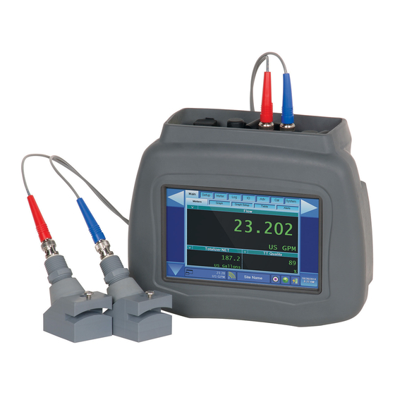
- Page 1 Hybrid Ultrasonic Flow Meters DXN Portable Ultrasonic Measurement System User Manual HYB-UM-00090-EN-04 (November 2016)
- Page 2 Hybrid Ultrasonic Flow Meters, DXN Portable Ultrasonic Measurement System Page ii HYB-UM-00090-EN-04 November 2016...
-
Page 3: Table Of Contents
User Manual CONTENTS Introduction . . . . . . . . . . . . . . . . . . . . . . . . . . . . . . . . . . . . . . . . . . . . . . . . . . . . . . . . . . . . . . . . . . . . . . . . . 7 Scope of This Manual . - Page 4 Hybrid Ultrasonic Flow Meters, DXN Portable Ultrasonic Measurement System Display Operation and Configuration . . . . . . . . . . . . . . . . . . . . . . . . . . . . . . . . . . . . . . . . . . . . . . . . . . . . . . . . 30 Main Group .
- Page 5 User Manual Cal (Calibration) Group . . . . . . . . . . . . . . . . . . . . . . . . . . . . . . . . . . . . . . . . . . . . . . . . . . . . . . . . . . . . . . . . . 70 Transit Page .
- Page 6 Hybrid Ultrasonic Flow Meters, DXN Portable Ultrasonic Measurement System K Factors . . . . . . . . . . . . . . . . . . . . . . . . . . . . . . . . . . . . . . . . . . . . . . . . . . . . . . . . . . . . . . . . . . . . . . . . . . 99 Description .
-
Page 7: Introduction
Introduction INTRODUCTION Scope of This Manual This manual is divided into two main sections: • “Meter Overview” on page 11 is intended to help you get the DXN flow metering system up and running quickly . Refer to the detailed instructions if you require additional information . •... -
Page 8: Electrical Considerations
Safety DO NOT CONNECT OR DISCONNECT EITHER POWER OR OUTPUTS UNLESS THE AREA IS KNOWN TO BE NON- HAZARDOUS. AVERTISSMENT RISQUE D’EXPLOSION. NE PAS DÉBRANCHER TANT QUE LE CIRCUIT EST SOUSTENSION, À MOINS QU’LL NE S’AGISSE D’UN EMPLACEMENT NON DANGEREUX. MPORTTNT Not following instructions properly may impair safety of equipment and/or personnel. -
Page 9: Important Safety & Usage Instructions
40 watts . Observe proper polarity . Note that extended operation on an automotive supply could substantially reduce the automotive battery . WARNING THE INTERNAL BATTERY PACK SHOULD ONLY BE REPLACED BY AN AUTHORIZED BADGER METER SERVICE REPRESENTATIVE. PLEASE CONTACT YOUR PRODUCT AND/OR SERVICE PROVIDER FOR INTERNAL BATTERY REPLACEMENT SERVICE. -
Page 10: Waste Electrical And Electronic Equipment (Weee) Directive
Safety Waste Electrical Tnd Electronic Equipment (WEEE) Directive In the European Union, this label indicates that this product should not be disposed of with household waste . It should be deposited at an appropriate facility to enable recovery and recycling . Declaration of Conformity The CE symbol on your product indicates that it is in compliance with the directives of the Union European (EU) . -
Page 11: Meter Overview
Meter Overview METER OVERVIEW General The DXN portable ultrasonic flow meter is designed to measure volumetric flow rate within a closed conduit . The transducers are a non-contacting, clamp-on or clamp-around type, which provide the benefits of non-fouling operation and ease of installation . -
Page 12: User Interface
Meter Overview User Interface The DXN flow meter has a sophisticated touchscreen user interface to control all functions . The tabbed menu tree provides access to all controls and settings within two layers of menus . Large, easy-to-read touchscreen buttons allow for gloved operation in inclement weather . -
Page 13: Dxn Flow Meter Data And Controls Layout
DXN Flow Meter Data and Controls Layout DXN FLOW METER DTTT TND CONTROLS LTYOUT Group & Page Tabs Navigate Navigate Menu Left Menu Right Left Context Right Context Sensitive Sensitive Area Area Data & Control Pages Status Bar Status Bar Navigation Button Figure 4: Main user screen layout... - Page 14 DXN Flow Meter Data and Controls Layout Buttons Button controls work in a similar manner to a push-button switch . Generally, they start or stop a function . Push-Button Figure 9: Push-button control Shutdown Slider Use the Shutdown Slider to turn off the DXN flow meter without having to press and hold the physical On/Off button . To use the shutdown slider, press the Down Trrow until the red Shutdown Slider appears .
- Page 15 DXN Flow Meter Data and Controls Layout Combo Box An arrow to the left of a box indicates the box contains a list of options . Combo Box Active Area Combo Box Water-Tap Indicator Figure 13: Retracted combo box Press the box’s active area to show the choices for that parameter . Cancel Water-Tap Water-Tap...
-
Page 16: Pre-Installation Checklist
Pre-Installation Checklist PRE-INSTTLLTTION CHECKLIST Charged Battery Charge the battery for four hours with the flow meter turned OFF . Tools Not Included with the Flow Meter • A 5/16 in . nut driver or a flat-head screwdriver • Permanent marker or other utensil that will make a visible mark on the pipe •... -
Page 17: Transducer Installation
Transducer Installation TRTNSDUCER INSTTLLTTION The transducers for the DXN flow meter contain piezoelectric crystals that transmit and receive ultrasonic signals through the walls of liquid piping systems . DTTR, DTTN, DTTL, DTTH and DT94 transducers are relatively simple and straightforward to install, but spacing and alignment of the transducers is critical to the system’s accuracy and performance . -
Page 18: Select A Mounting Location
Transducer Installation Select a Mounting Location At this point, consider the transducer mounting location . A guiding principle is to mount the transducers on a section of pipe that has at least 10 pipe diameters upstream of the transducers and 5 pipe diameters downstream . See Table 1 on page 19 for additional pipe length considerations . - Page 19 Transducer Installation Piping Con guration Upstream Downstream Pipe Pipe and Transducer Positioning Diameters Diameters Flow Flow Flow Flow Flow Flow Table 1: Piping configuration and transducer positioning The DXN flow metering system provides repeatable measurements on piping systems that do not meet these pipe diameter requirements, but the accuracy of the readings may be influenced .
-
Page 20: Select A Mounting Configuration
Transducer Installation Select a Mounting Configuration The flow meter can be used with these transducer types: DTTR, DTTN, DTTL, DTTH, DTTSU and DT94 . Meters that use transducer sets consist of two separate sensors that function as both ultrasonic transmitters and receivers . The transducers are clamped on the outside of a closed pipe at a specific distance from each other . - Page 21 Transducer Installation Transducer Transducer Pipe Material Pipe Size Mount Mode Plastic (all types) Carbon Steel 0 .5…0 .75" (12 .7…19 mm) Stainless Steel W-Mount Copper Galvanized Not recommended DTTSU Plastic (all types) Carbon Steel 0 .75…2 .4" (19…61 mm) V-Mount Stainless Steel Copper Galvanized...
-
Page 22: Enter The Site, Fluid And Pipe Properties
Transducer Installation Enter the Site, Fluid and Pipe Properties The DXN has the ability to store over 300 sites . Each site contains fluid and piping characteristics as well as other settings that are configured during meter commissioning . Sites are recallable from a pull-down menu each time the specific site is visited . This makes period measurements of the particular site less time consuming . -
Page 23: Mount The Transducer
Transducer Installation Mount the Transducer After selecting an optimal mounting location and determining the proper transducer spacing, mount the transducers onto the pipe . 1 . Clean the surface of the pipe . If the pipe has external corrosion or dirt, wire brush, sand or grind the mounting location until it is smooth and clean . - Page 24 Transducer Installation OTEE: Use the DTTL transducer on pipes 24 inches and larger and not on pipes smaller than 4 inches . You Transducer can consider using the DTTL transducers on pipes Spacing smaller than 24 inches if there are less quantifiable aspects—such as sludge, tuberculation, scale, rubber liners, plastic liners, thick mortar liners, gas bubbles, suspended solids, emulsions—and smaller pipes...
- Page 25 Transducer Installation Edge of Paper Line Marking Circumference Fold Pipe Circumference Transducer Spacing Crease LESS THAN ¼” (6 mm) (Center of Pipe) Figure 23: Bisecting the pipe circumference Figure 22: Paper template alignment 5 . For DTTR, DTTN, DTTL and DTTH transducers, place a single bead of couplant, approximately 1/2 inch (12 mm) thick, on the flat face of the transducer .
- Page 26 Transducer Installation Mounting Rail System Installation for DTTR For remote flow DTTR transducers with outside diameters between 2…10 inches (50…250 mm), the rail mounting kit aids in installation and positioning of the transducers . Transducers slide on the rails, which have measurement markings that are viewable through the sight opening .
-
Page 27: Dttsu Small Pipe Transducer Installation
Transducer Installation DTTSU Small Pipe Transducer Installation Mount DTTSU transducers with the cable exiting within ±45 degrees of the side of a horizontal pipe . On vertical pipes the orientation does not apply . The DTTSU small pipe transducers are adjustable for pipe sizes between 1/2…2 in . (12…50 mm) . Do not attempt to mount a DTTSU transducer onto a pipe that is either too large or too small for the transducer . -
Page 28: Doppler Transducer Installation
Transducer Installation Chain Mounting Cleat ½” (12 mm) Figure 30: Application of acoustic couplant for DTTSU transducers 4 . Finger tighten the thumb screws so that the acoustic coupling grease begins to flow out from the under the transducer . Do not over tighten . - Page 29 The most economical way to affix DTTR, DTTN, DTTH, DTTL and DT94 transducers to a pipe is by using adjustable mounting straps . Individual straps in both 36 in . (900 mm) and 72 in . (1830 mm) are available from Badger Meter . See...
-
Page 30: Display Operation And Configuration
Display Operation and Configuration DISPLTY OPERTTION TND CONFIGURTTION CAUTION THE DXN IS DESIGNED TO OPERATE FOR EXTENDED PERIODS WITH FREE AIR MOVEMENT TO COOL THE METER. THE UNIT SHOULD NOT BE OPERATED FOR MORE THAN 30 MINUTES IN A CLOSED CASE INCLUDING THE CANVAS CARRYING CASE. - Page 31 PC CPU: 12% 138MB 54C Battery: 35%, -1.0A, 42.0C Setup Wizard << Press button to begin Guided Setup Wizard Begin Wizard Version L About Status Bar ©2014 Badger Meter, Inc. Shutdown Bar > > > Slide To Shut Down >...
-
Page 32: Main Group
Main Group MTIN GROUP Setup Main Meter System Meters Graph Graph Setup Table Alerts Figure 37: Main group Meters Page The Meters page displays system data, such as the current reading and units of measurement . Meters On Screen Button Metering Parameter Current... -
Page 33: Graph Page
Main Group Table 5 shows the metering parameter choices . Flow Energy NET DOP Quality TT Aperture Start Totalizer NET Energy POS TT Flow Velocity RTD1 Temperature Totalizer POS Energy DOP TT Delta T RTD2 Temperature Totalizer NEG Energy NEG TT Delta T Raw RTD Delta Temp Totalizer DOP... -
Page 34: Graph Setup Page
Main Group Axes Axes Axes Axes Y Lt Y Rt Home Axes Axes Home Axes Axes Y Lt Y Rt Figure 41: Graph axis configuration Graph Setup Page Figure 42: Main > Graph setup Left and Right Txis Data The Left and Right Axis Data controls which parameters are shown on the respective axis . See Table 6 for parameter choices . -
Page 35: Table
Main Group Time Range The Time Range control selects a period to be shown on the X axis . See Table 7 for the time choices . When you press the control, a drop-down menu appears . Highlight a parameter with the blue box and press Set to load the parameter . Press X to exit the drop-down menu . -
Page 36: Alerts Page
Main Group Tlerts Page Figure 45: Main > Alerts The Alerts page keeps track of any abnormal conditions encountered by the meter . Such things as battery condition, unit temperature issues, low signal quality episodes and fluid sound speed problems are shown in the alerts page until they are resolved . -
Page 37: Setup Group
Setup Group SETUP GROUP Main Setup Meter System Site Fluid ANSI Pipe Pipe Liner Transit Doppler Figure 46: Setup group The Setup group is used to create and store individually configured metering locations . Each new location can be stored with all the setup parameters for that particular site, making periodic measurements less time consuming . - Page 38 Setup Group Load Defaults Settings Loading the factory defaults returns the meter to a known state for most of the customer-selectable parameters . The default settings do not include basic setup parameters such as pipe size, pipe type, and fluid type . To prevent unintended loading of the default settings, you must check the Unlock Load Default Settings box to activate the Load Default Settings function .
-
Page 39: Fluid Page
Setup Group Fluid Page Select Setup from the Group bar at the top of the screen . When the site page appears, select the Fluid page to enter information about the type of fluid to be used . OTEE: Use the Fluid page also to start the entry of information about a custom fluid . Figure 49: Fluid setup OTEE: Use the scroll bars to the right of the menu choices to display more information than can be seen on one page . - Page 40 Setup Group Figure 50: Custom fluid setup Custom Fluid Sound Speed (Numeric Value) Enter the sound speed of the custom fluid . If English is used for the Entry Units enter the sound speed in fps . If Metric is used the sound speed is entered in mps .
-
Page 41: Ansi Pipe Page
Setup Group If a fluid from the Fluid Material list is chosen, a default specific heat is automatically loaded . If the actual specific heat of the liquid is known or it differs from the default value, the value can be revised . A list of alternate fluids and their associated specific heat capacities is located in the Appendix of this manual . -
Page 42: Pipe Page
Setup Group Pipe Schedule/Class The choice of pipe material determines the options available in the Schedule/Class drop-down list . For example, if you select a pipe material that is governed by ANSI standards, the option label is ANSI Schedule and the schedule choices are appropriate for ANSI pipe . - Page 43 Setup Group Use the Setup > Pipe page to manually enter pipe parameters . If you used the lookup function in Setup > ANSI Pipe, nominal values for Pipe OD, Pipe Wall [Thickness] and Roughness are automatically entered . If the actual values of the pipe differ from the ones automatically entered, go back to Setup >...
- Page 44 Setup Group Figure 55: Setup > Pipe US — schedule manual entry selected 2 . In the Setup > Pipe screen, make sure that the Pipe Material and Pipe OD have been entered as in Figure 56 . 3 . The pipe wall thickness gauge uses the same input connectors as the transit time ultrasonic transducers . The thickness gauge has two BNC connectors with red and blue markings .
- Page 45 Setup Group Ultrasonic Thickness Gauge Close Aluminum OD=1.4 in Best Peak Peak 1 Peak 2 Automatic Analysis Mode 0.387 in 0.319 in 0.500 in 01P Thin Metal Pipe 35000 21000 7000 -7000 -21000 Thickness Waveform Thickness Envelope -35000 Remove from Pipe and Clean Transducer Store to Pipe Wall Setting THEN Check to Lock Reference 0.422 in...
- Page 46 Setup Group Ultrasonic Thickness Gauge Close Aluminum OD=1.4 in Best Peak Peak 1 Peak 2 Automatic Analysis Mode 0.387 in 0.319 in 0.500 in 01P Thin Metal Pipe 35000 21000 7000 -7000 -21000 Thickness Waveform Thickness Envelope -35000 Apply Transducer and Couplant to Pipe Store to Pipe Wall Setting THEN Check to Lock Reference 0.422 in...
- Page 47 Setup Group Tdvanced Mode The advanced mode is intended users with knowledge of ultrasonic testing or when automatic settings are not appropriate . To enter Advanced Mode, uncheck Tutomatic Tnalysis Mode . The manual settings reflect the automatic settings when the wizard first opens .
-
Page 48: Liner Page
Setup Group Liner Page Figure 61: Setup > Liner page Liner Material Choose the pipe liner material from the drop-down list . The following list is an example . Additional materials are added periodically . Select the liner material from the list . If the exact liner material is not listed, choose one that most closely represents it . -
Page 49: Transit Page
Setup Group Transit Page Figure 62: Setup > Transit Transducer Select a transducer from the drop-down list . Transducer transmission frequencies are specific to the type of transducer . Transducer Frequency Type Use for Pipe Sizes DTTR/DTTN Standard Transducers 1 MHz 2…98 in . -
Page 50: Doppler Page
Setup Group Doppler Page Figure 63: Doppler transducer selection To use the Doppler measuring, select the DT94 series transducers . At this time, the DT94 series are the only Doppler transducers supported . Page 50 HYB-UM-00090-EN-04 November 2016... -
Page 51: Meter Group
Meter Group METER GROUP Site Display Meter System Flow Totalizer Limit Filter Energy Figure 64: Meter group Select the Meter Group from the Group bar at the top of the screen . When the Meter pages appear select the flow page to enter information about the flow units to be used . -
Page 52: Totalizer Page
Meter Group Totalizer Page Figure 66: Totalizer setups Total Units From the pull-down list, select an engineering unit for flow accumulator (totalizer) measurements . US Gallons Acre Foot Liters Oil Barrels (42 Gallons) Mega US Gallons Liquid Barrels (31 .5 Gallons) Cubic Feet Feet Cubic Meters... -
Page 53: Limit Page
Meter Group Limit Page Figure 67: Limit value settings Min Flow Limit A minimum rate setting establishes the filter software parameters and the lowest rate value to display . Volumetric entries display in the Flow Units selected in Meter > Flow . •... -
Page 54: Filter Page
Meter Group Filter Page Figure 68: Filter settings Filter Method The DXN flow meter offers several levels of signal filtering: • None imposes no filtering on the signal from the transducers . • Simple with Rejection uses Damping and Bad Data Rejection to filter the flow data . •... - Page 55 Meter Group Flow Within ±10% Hysteresis Hysteresis Limit Limit Flow Figure 69: Hysteresis window Bad Data Rejection (Range 0…10 Samples) The Bad Data Rejection setting is related to the number of successive readings that must be measured outside of a the Hysteresis value before the flow meter considers the new flow value valid .
-
Page 56: Energy Page
Meter Group The flow rate is again outside the original ±10% Hysteresis window, but the data exists for a time period greater than the Bad Data Rejection window . In this instance, the meter interprets the data as a new valid flow rate and moves the Hysteresis window to correspond with the new established flow rate . -
Page 57: Log (Data Logging) Group
Log (Data Logging) Group LOG (DTTT LOGGING) GROUP Setup Main Meter System Setup Select Data Figure 73: Log Group Setup Page The setup screen controls the selection of the Logging Rate and has a software button for starting and stopping logging sessions . -
Page 58: Select Data Page
Log (Data Logging) Group Logging Duration Logging Rate (Once every #) Samples/Second Minutes Hours Days 0 .1 second (10 Hz) 1 .8 0 .08 1 second 1092 18 .2 0 .76 2 seconds 0 .5 2183 36 .4 1 .52 5 seconds 0 .2 5458... - Page 59 Log (Data Logging) Group Column 2E: User, Column 3E: User, Column 4E: User The three user-defined fields can be configured to capture any of the following values . Nothing Flow Totalizer Net Flow Velocity Reynolds Number Power Energy Net TT Flow TT Gain TT Quality DOP Flow...
-
Page 60: I/O (Input / Output) Group
I/O (Input / Output) Group I/O (INPUT / OUTPUT) GROUP Setup Main Meter System Set Out Scale Out Set In Test Out Figure 77: I/O group Set Out (Setup Outputs) Page Figure 78: Data outputs setup The I/O > Set Out option determines which of the flow meter’s outputs are active . •... -
Page 61: Scale Out (Scale Outputs) Page
I/O (Input / Output) Group Scale Out (Scale Outputs) Page Figure 79: Scale outputs setup The I/O > Scale Out sets the parameter to which the output circuitry responds . Data to Output Choices for Data To Output are Flow and Power . Flow at Min Out Flow at Min Out sets the minimum value to which the outputs are scaled . -
Page 62: Set In (Setup Input)
I/O (Input / Output) Group Set In (Setup Input) Figure 81: Input setup Digital Input Mode • Off: Disables the Digital input • Reset at 0 Volts: Resets totalizers when the digital input voltage is equal to zero . Voltage Input Mode The Voltage Input mode contains 3 choices . -
Page 63: Test Out (Test Outputs) Page
I/O (Input / Output) Group Test Out (Test Outputs) Page Figure 82: Test outputs setup The Test Out options are used to calibrate devices connected to the flow meter through the I/O breakout box . To use this function: 1 . Connect the output to a device designed to read that type of output signal . •... -
Page 64: Adv (Advanced) Group
The Advanced group tab provides users a way to troubleshoot problematic applications, as well as setting up the flow meter to best suit application needs . Pages within this tab should only be modified under the guidance of Badger Meter Technical Support or with caution . - Page 65 Adv (Advanced) Group Txes Scaling Buttons Press the Txes button successively to move through the three axis configuration choices, as shown in Figure 85 . The X axis is always time based . Press + magnifying glass or – magnifying glass to expand or contract the timeline shown on the horizontal (X axis) .
-
Page 66: Transit Page
Adv (Advanced) Group Transit Page Figure 86: Advanced transit time setup Tuto Tx or 1/Tmp • Transmit attenuation . • When box is checked, attenuation is automatic) . • When box is unchecked, attenuation is manual . 1…16 time attenuation . If 16, then transmitted signal is 1/16th full power . Transit TGC or Gain •... -
Page 67: Waveform Page
Figure 87: Advanced waveform selection For most applications, select the Tutomatic waveform . In some circumstances, you may select an alternate waveform at the direction of Badger Meter Technical Support . Tutomatic Pull-Down List Options This controls the transmitted waveform . This is very useful for various flow conditions . -
Page 68: Doppler Page
Adv (Advanced) Group Doppler Page Figure 88: Advanced Doppler setup Doppler Tx Freq (kHz) Read only . Doppler baseband frequency (usually 625 kHz) . Custom Transducer Tngle (deg) Read only . Doppler Transducer Launch Angle (30 .00°) . Doppler Sample Rate Control Read only . -
Page 69: Monitor Page
Adv (Advanced) Group Monitor Page Figure 89: Advanced monitor Waveform Update Rate (s) Read only . Waveform update rate . Default is 1 update per 5 seconds only when waveform tab is visible . Snapshot Rate (s) Read only . Data snapshot rate . Default is 1 update per 1 second . System Info Rate (s) Read only . -
Page 70: Cal (Calibration) Group
20 gpm, a user adjustment of “2 .000” will modify the flow rate to 40 gpm . OTEE: Only use this under the guidance of Badger Meter Technical Support . Default should always be “1 .000” . Positive Flow As of Rev K, the Positive flow checkbox is always marked . This checkbox will be used to allow reversal of measurement . - Page 71 Cal (Calibration) Group SOS Comp When SOS Comp is not checked, the flowmeter equation simply uses the soundspeed from the lookup table as: fluid fluid from lookup table When SOS Comp is checked, the flowmeter equation uses the soundspeed as measured from the signals: fluid fluid fluid...
-
Page 72: Doppler Page
20 gpm, a user adjustment of “2 .000” will modify the flow rate to 40 gpm . OTEE: Only use this under the guidance of Badger Meter Technical Support . Default should always be “1 .000” . Positive Flow This is always grayed and checked . Doppler flow is always positive for our instruments as of 2014 . -
Page 73: Factory Page
Cal (Calibration) Group Factory Page The factory calibration page shows all the parameters stored in the flow meter’s memory, originally derived during calibration . These are the values that re-load when you use press Load Default Settings from Setup > Site . Figure 93: Factory calibration (page 1) Figure 94: Factory calibration (page 2) Store Cal Table... -
Page 74: System Group
System Group SYSTEM GROUP Main Setup Meter System Misc Power Disk Storage ENet Time Update Comm Figure 95: System group Misc (Miscellaneous) Page Figure 96: System miscellaneous Language Use the Language pull-down list to select the language for screen displays . English Deutsch Français... -
Page 75: Power Page
System Group Power Page The System > Power page has a group of lights that indicate the state of the internal Lithium-Ion battery . The flow meter has a sophisticated battery management circuit that provides a long trouble-free battery life . The meter can remain connected to the charger without over-charging the battery . -
Page 76: Disk Page
System Group Disk Page Figure 98: System disk The System > Disk page provides information about the meter’s hard disk storage capacity . The flow meter uses an 8 gigabyte hard drive, of which, 1 gigabyte is available to the user . PC Page Figure 99: System PC PC CPU STTTUS... -
Page 77: Storage Page
System Group Storage Page Figure 100: System storage The System > Storage page helps you manage the sites stored in the flow meter’s memory . To manage a site: Use the Select Site to Manage pull-down list to choose the site to be modified or deleted . Once the site is selected several actions become available . -
Page 78: Enet Page
System Group Restore Sites from USB Site configurations can be uploaded from a USB to the DXN memory . 1 . Insert a USB with copied site information to the USB port on top of the unit . 2 . Wait one minute to ensure connectivity between the UDB drive and the DXN . 3 . - Page 79 System Group Modbus TCP Connection Instructions Bits Bytes Modbus Registers Long Integer Single Precision IEEE754 Double Precision IEEE754 Table 21: Modbus data formats Modbus Register / Word Ordering Each Modbus Holding Register represents a 16-bit integer value (2 bytes) . The official Modbus standard defines Modbus as a ‘big-endian’...
- Page 80 System Group Figure 103: Modbus TCP server enabled Figure 104: Modbus TCP server disabled 4 . Press Edit to change IP Address or Subnet Mask to the desired setting for the network . Figure 105: Edit buttons Figure 106: IP address edited Figure 107: Subnet mask edited 5 .
- Page 81 System Group Modbus Register Addresses MODBUS Registers Floating Point Tvailable Units Long Integer Single Precision Double Precision Data Component Name Format Format Format Signal Strength 40100 - 40101 40200 - 40201 40300 - 40303 Flow Rate 40102 - 40103 40202 - 40203 40304 - 40307 Gallons, Liters, MGallons, Cubic Feet, Cubic Meters, Acre Feet, Oil Barrel, Liquid Barrel, Feet,...
-
Page 82: Time Page
3 . Press Press to Set Time to load the settings into the system memory . Update Page The System > Update page is used in conjunction with software updates supplied by Badger Meter to install new software revisions into the DXN system . For complete updating instructions, see “Upgrading Software”... -
Page 83: Comm (Communications) Page
System Group Comm (Communications) Page Figure 110: System communications (comm) The Comm page is mostly for engineering and debugging purposes . The scrolling blue and black text indicates proper communication . Disconnect Pull-Down Menu Use this selection to connect or disconnect communication to the flow meter . No TT Flow Sim Indicates the status of flow simulation . -
Page 84: Inputs/Outputs
Inputs/Outputs INPUTS/OUTPUTS General The DXN system offers a variety of input and output options . The individual I/O connections are accessed by using the included Breakout Box connected to the flow meter via a DB15 cable connection labeled Process I/O . I/O connection Figure 111: Display I/O connection DB15... -
Page 85: Digital Outputs
Inputs/Outputs Digital Outputs Digital/Pulse Outputs The digital output is an open collector transistor which must have a pull-up resistor to function . The output can be configured as either a frequency output scale, based upon the minimum and maximum flow rate chosen, or a totalizing pulse controlled by the incrementing totalizer . - Page 86 Inputs/Outputs Rate Pulse Scaling The rate pulse has a maximum frequency of 1000 Hz that is proportional to the minimum and maximum user flow rates entered . Setting the minimum and maximum flow rates is accomplished using the Meter > Limit software controls . For example, if the minimum flow rate were set to –100 gpm and the maximum flow rate was +100 gpm the 1000 Hz output would span the distance from –100…100 gpm .
-
Page 87: Analog Outputs
Inputs/Outputs Tnalog Outputs Analog outputs are signals that change continuously over time . In most control applications, analog signals range continuously over a specified current or voltage . The DXN offers a DC voltage output and two styles of 4…20 mA current output . - Page 88 Inputs/Outputs 4…20 mT Current Output (Current Sourcing) 0V DC (Ground) Jumper 4 . . . 20 mA Signal Figure 118: 4…20 mA current sourcing output The current output from the DXN can also be configured to source current . With terminals 6 and 7 jumpered together . 15V DC Supply (30 mT Max) The DXN has a built in power supply that can be used to power current or voltage sensors external to the meter .
-
Page 89: Upgrading Software
Upgrading Software UPGRTDING SOFTWTRE MPORTTNT The Dynasonics USB Flash Drive is formatted in FAT/FAT32. NTFS (New Technology File System) formats do not work. The upgrade is supplied as a self extracting zip file and must be expanded on a PC before it can be loaded into the DXN . 1 . - Page 90 Upgrading Software 5 . Insert the thumb drive into the USB port on the rear of the flow meter . 6 . From the Main > Meters screen, press the System tab on the far right of the top menu display . 7 .
- Page 91 Upgrading Software 12 . After the reboot, the screen shows a grayed-out Software Update button . When the update drive is inserted, the grayed out button illuminatios . Press Start Updater after it illuminates . 13 . The meter returns to the Update screen . Press Update System Step 2: Update System (Reboot) . OTEE: If this step was completed in a previous system update, the update utility may skip directly to Copy Step 3: Copy Updated Files .
- Page 92 Upgrading Software When the opening screen appears, insert the USB Update Drive . The “Software Update“ message again becomes selectable . 15 . Press Start Updater . 16 . Press Copy Step 3: Copy Updated Files . The text area to the right displays a series of status messages that ends with “Copying Files Complete 100 Files”...
- Page 93 Upgrading Software When the update process completes, green checkmarks appear in the boxes next to steps 1, 2, 3 and 4 . 18 . Press Lock Step 5: Lock System (Reboot), remove the USB drive and press OK to reboot . OTEE: If the thumb drive is not removed before you press OK, the unit may lock-up .
-
Page 94: Quick Boot
Upgrading Software Quick Boot 1 . To enable Quick Boot, from the main screen, select System > Update and then press Set Up Quick Boot . The application closes, reverting to the system menu . 2 . Press Start Flow Meter again . The unit enters a hibernation process and shuts down . On the next power up, the unit starts in Quick Boot mode . -
Page 95: Microsoft Software License Terms For Windows Xp Embedded And Windows Embedded Standard Runtime
TND WINDOWS EMBEDDED STTNDTRD RUNTIME These license terms are an agreement between you and Badger Meter . Please read them . They apply to the software included on this device . The software also includes any separate media on which you received the software . -
Page 96: Scope Of License
Scope of License The software is licensed, not sold . This agreement only gives you some rights to use the software . Badger Meter and Microsoft reserve all other rights . Unless applicable law gives you more rights despite this limitation, you may use the software only as expressly permitted in this agreement . -
Page 97: Windows Update Agent (Also Known As Software Update Services)
. To be valid, this label must be affixed to the device, or included on or in the Badger Meter software packaging . If you receive the label separately, it is not valid . You should keep the label on the device or packaging to prove that you are licensed to use the software . -
Page 98: Not Fault Tolerant
Microsoft Software License Terms for Windows XP Embedded and Windows Embedded Standard Runtime Not Fault Tolerant The software is not fault tolerant . Badger Meter installed the software on the device and is responsible for how it operates on the device . -
Page 99: K Factors
K Factors K FTCTORS Description The K factor (with regards to flow) is the number of pulses that must be accumulated to equal a particular volume of fluid . You can think of each pulse as representing a small fraction of the totalizing unit . An example might be a K factor of 1000 (pulses per gallon) . - Page 100 K Factors Find the area of the pipe cross section . Area = πr 3.068 Area = π = π x 2.35 = 7.39 in Find the volume in one foot of travel . 88.71in 7.39 in x 12 in.
-
Page 101: Specific Heat Capacity Values For Fluids
Specific Heat Capacity Values for Fluids SPECIFIC HETT CTPTCITY VTLUES FOR FLUIDS Temperature Specific Heat 32…212° F 0…100° C 1 .00 Btu/lb° F 250° F 121° C 1 .02 Btu/lb° F 300° F 149° C 1 .03 Btu/lb° F 350° F 177°... -
Page 102: Specifications
Specifications SPECIFICTTIONS Process Monitoring Inputs/Outputs Connector 15-pin high-density DSUB Breakout Box 0 .2 in . quick disconnect screw terminal; 15-pin to adapter box; 6 ft (1 .8 m) of cable (DSUB to DSUB connectors) Energy/Temperature (2) tab type PT1000 RTDs . RTD Input Can handle various temperature ranges from –58…392º... -
Page 103: North American Pipe Schedules
North American Pipe Schedules NORTH TMERICTN PIPE SCHEDULES Steel, Stainless Steel, PVC Pipe, Standard Classes SCH 60 X STG. SCH 80 SCH 100 SCH 120/140 SCH 180 Wall Wall Wall Wall Wall Wall 1 .315 0 .957 0 .179 0 .957 0 .179 0 .815 0 .250... - Page 104 North American Pipe Schedules Copper Tubing, Copper and Brass Pipe, Tluminum Copper Tubing Copper Tubing Copper Copper Nominal Nominal & Brass Tlum. & Brass Tlum. Diameter Diameter Pipe Pipe Type Type 0 .625 0 .625 0 .625 0 .840 3 .625 3 .625 3 .625 4 .000...
- Page 105 North American Pipe Schedules Cast Iron Pipe, Standard Classes, 3…20 inch Class Size 3 .80 3 .96 3 .96 3 .96 Wall 0 .39 0 .42 0 .45 0 .48 — — — — 3 .02 3 .12 3 .06 3 .00 4 .80 5 .00...
- Page 106 North American Pipe Schedules Cast Iron Pipe, Standard Classes, 24…84 inch Class Size 25 .80 25 .80 26 .32 26 .32 26 .90 26 .90 27 .76 27 .76 Wall 0 .76 0 .98 1 .05 1 .16 1 .31 1 .45 1 .75 1 .88...
-
Page 107: Fluid Properties
Fluid Properties FLUID PROPERTIES Sound Speed Specific Gravity delta-v/° C Kinematic Tbsolute Fluid m/s/° C Viscosity (cSt) Viscosity (Cp) 20° C ft/s Acetate, Butyl — 4163 .9 1270 — — — Acetate, Ethyl 0 .901 3559 .7 1085 4 .4 0 .489 0 .441 Acetate, Methyl... - Page 108 Fluid Properties Sound Speed Specific Gravity delta-v/° C Kinematic Tbsolute Fluid m/s/° C Viscosity (cSt) Viscosity (Cp) 20° C ft/s Linseed Oil 0 .925…0 .939 5803 .3 1770 — — — Methanol 0 .79 3530 .2 1076 2 .92 0 .695 0 .550 Methyl Alcohol 0 .79...
-
Page 109: Glossary
Glossary GLOSSTRY Auto Tx or 1/Amp Transmit attenuation Automatic Parameter that automatically picks related options 3, 5, 7, 11 or 13 sine wave chips . Chips and wavelengths per chip are determined with Best Barker transducer and setup . Frequency can be adjusted . Chip count is adjusted automatically to Duration Best Barker Square Uses square wave chips... - Page 110 Glossary An analysis that is best suited for sine wave type output waveforms (Sin, Sine Carrot Top) . Harmonic NoPH No peak hop detection is implemented User can select transit time only, Doppler only, or automatic switching between Doppler Hybrid Mode and transit time IO Current Out Current value of the current output...
- Page 111 Glossary TT Fluid Velocity Transit time fluid velocity TT Gain Transit time automatic gain control override TT K Custom Transit time user adjustment TT K Reynolds Transit time Reynolds adjustment (always 1, will be 0 .75…1 .00 in future) TT Margin P Transit time (future use) Transit time, as measured from cross correlation, is the ratio of picked flow peak to the TT Margin X...
- Page 112 The Americas | Badger Meter | 4545 West Brown Deer Rd | PO Box 245036 | Milwaukee, WI 53224-9536 | 800-876-3837 | 414-355-0400 México | Badger Meter de las Americas, S.A. de C.V. | Pedro Luis Ogazón N°32 | Esq. Angelina N°24 | Colonia Guadalupe Inn | CP 01050 | México, DF | México | +52-55-5662-0882...
Need help?
Do you have a question about the Dynasonics DXN and is the answer not in the manual?
Questions and answers