Table of Contents
Advertisement
HPE ProLiant XL170r Gen10 Server User
Guide
Abstract
This document is for the person who installs, administers, and troubleshoots servers and
storage systems. Hewlett Packard Enterprise assumes you are qualified in the servicing of
computer equipment and trained in recognizing hazards in products with hazardous energy
levels.
Part Number: 879108-003
Published: June 2018
Edition: 3
Advertisement
Table of Contents

Related Manuals for HPE ProLiant XL170r Gen10


Summary of Contents for HPE ProLiant XL170r Gen10
- Page 1 HPE ProLiant XL170r Gen10 Server User Guide Abstract This document is for the person who installs, administers, and troubleshoots servers and storage systems. Hewlett Packard Enterprise assumes you are qualified in the servicing of computer equipment and trained in recognizing hazards in products with hazardous energy levels.
- Page 2 © Copyright 2017, 2018 Hewlett Packard Enterprise Development LP Notices The information contained herein is subject to change without notice. The only warranties for Hewlett Packard Enterprise products and services are set forth in the express warranty statements accompanying such products and services. Nothing herein should be construed as constituting an additional warranty. Hewlett Packard Enterprise shall not be liable for technical or editorial errors or omissions contained herein.
-
Page 3: Table Of Contents
Contents Component identification...............6 Rear panel components........................6 Rear panel LEDs and buttons.......................6 Power fault LEDs........................7 System board components......................8 Processor, heatsink, and socket components..............9 System maintenance switch descriptions................ 10 Bayonet board components......................10 PCIe riser board slot definitions....................11 Primary riser components....................11 FlexibleLOM 1U riser......................12 1U secondary riser for processor 1.................. - Page 4 Installing the S100i SATA cable assembly.................. 55 HPE Trusted Platform Module 2.0 Gen10 option................57 Overview.......................... 57 HPE Trusted Platform Module 2.0 Guidelines..............58 Installing and enabling the HPE TPM 2.0 Gen10 Kit............59 Cabling....................64 Cabling overview.........................64 Cabling guidelines........................64 Storage cabling........................... 66 S100i SATA controller......................
- Page 5 Temperature requirements for the HPE ProLiant XL170r Gen10 Server........90 List of components with temperature requirements in the HPE ProLiant XL170r Gen10 Server........................90 Drive blank installation guidelines for the HPE ProLiant XL170r Gen10 Server....96 Websites....................98 Support and other resources...............99 Accessing Hewlett Packard Enterprise Support.................
-
Page 6: Component Identification
Component identification Rear panel components Item Description Slot 1 PCIe3 x16 (16, 8, 4, 1) Slot 2 PCIe3 x16 (16, 8, 4, 1) or FlexibleLOM SUV connector iLO Management Port iLO Service Port Media Module (optional - NIC ports) Server serial number and iLO label pull tab USB 3.0 port If the RCM module is installed on the chassis, the iLO Management Port will be automatically disabled. -
Page 7: Power Fault Leds
Item Description Status NIC link LED Green = Linked to network Off = No network connection NIC activity LED Green or flashing green = Network activity Off = No network activity Health LED Solid green = Normal Flashing green = iLO rebooting Flashing amber = System degraded Flashing red = System critical Do not remove LED... -
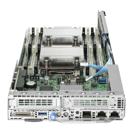
Page 8: System Board Components
7 flashes Power backplane or storage backplane 8 flashes Power supply 9 flashes System board components NOTE: HPE ProLiant XL170r and XL190r Gen10 Servers share the same system board. Item Description Primary riser slot 1 Media Module connector System battery Fabric carrier sideband signal connector M.2 SSD riser connector... -
Page 9: Processor, Heatsink, And Socket Components
Item Description Processor 2 DIMMs for processor 2 Bayonet board slot Secondary riser slot 4 Secondary riser slot 3 Slimline SATA x4 connector System maintenance switch Slimline SATA x8 connector Secondary riser slot 2 TPM connector microSD slot Processor, heatsink, and socket components Item Description Heatsink nuts... -
Page 10: System Maintenance Switch Descriptions
System maintenance switch descriptions Position Default Function Off = iLO security is enabled. On = iLO security is disabled. — Reserved Reserved Reserved Off = Power-on password is enabled. On = Power-on password is disabled. 1, 2 Off = No function On = Restore default manufacturing settings —... -
Page 11: Pcie Riser Board Slot Definitions
Item Description Port 1 Port 2 PCIe riser board slot definitions Primary riser components Item Form Factor Slot number Description Storage controller or low-profile PCIe3 x16 (16, 8, 4, 1) for Processor PCIe expansion board — — Storage backup power connector PCIe riser board slot definitions... -
Page 12: Flexiblelom 1U Riser
FlexibleLOM 1U riser Item Form Factor Slot number Description FlexibleLOM FlexibleLOM slot PCIe3 x16 for Processor 1 Slimline SAS cable for NVMe — Port 1 support Not shown 1U secondary riser for processor 1 Item Form Factor Slot number Description —... -
Page 13: Secondary Riser For Processor 2
1U secondary riser for processor 2 NOTE: The HPE XL170r 16NVMe Gen10 P2 LP Riser Kit (PN 874304-B21) is only for use in servers that are installed in the HPE Apollo r2800 Gen10 Chassis with 16 NVMe. For more information, see Cabling. -
Page 14: M.2 Ssd Riser Bay Numbering
M.2 SSD riser bay numbering Item Description Bay 7 Bay 8 The arrow points toward the server tray handle. M.2 SSD riser bay numbering... -
Page 15: Setup
Delivered by experienced, certified engineers, Hewlett Packard Enterprise support services help you keep your servers up and running with support packages tailored specifically for HPE ProLiant systems. Hewlett Packard Enterprise support services let you integrate both hardware and software support into a single package. -
Page 16: Server Warnings And Cautions
Server warnings and cautions WARNING: This server is heavy. To reduce the risk of personal injury or damage to the equipment: • Observe local occupational health and safety requirements and guidelines for manual material handling. • Get help to lift and stabilize the product during installation or removal, especially when the product is not fastened to the rails. -
Page 17: Installing The Chassis Into The Rack
4. Install the operating system. 5. Register the product. Installing the chassis into the rack To install the chassis into the rack, see the HPE Apollo 2000 Gen10 Chassis User Guide on the Hewlett Packard Enterprise website. Installing hardware options Before installing and initializing the server, install any hardware options. -
Page 18: Registering The Server
a. To enter the UEFI System Utilities screen and modify the server configuration ROM default settings, press the F9 key on the ProLiant POST screen. Choose one of the following boot modes: • Legacy BIOS • UEFI (default) b. If you do not need to modify the server configuration and are ready to install the system software, press the F10 key to access Intelligent Provisioning. -
Page 19: Operations
Operations This chapter describes the hardware operations carried out prior to and after installing or removing a hardware option, or performing a server maintenance or troubleshooting procedure. Before performing these hardware operations, review and observe the server warnings and cautions. Powering up the server The SL/XL Chassis Firmware initiates an automatic power-up sequence when the servers are installed. -
Page 20: Installing The Server Tray Blank
Procedure Remove the server tray blank. Installing the server tray blank CAUTION: To ensure proper thermal cooling, all server tray slots must be populated with servers or server tray blanks. Procedure Install the server tray blank. Installing the server tray blank... -
Page 21: Removing The Server From The Chassis
Removing the server from the chassis CAUTION: Before powering down the server, perform a backup of critical server data and programs. Removing the server while the Do not remove LED is on may result in data loss or corruption. CAUTION: To avoid damage to the server, always support the bottom of the server when removing it from the chassis. -
Page 22: Installing The Server Into The Chassis
CAUTION: To avoid damage to the device, do not use the removal handle to carry the server. Installing the server into the chassis CAUTION: To avoid damage to the device, do not use the removal handle to carry it. Procedure 1. -
Page 23: Removing The Air Baffle
2. Connect all peripheral cables to the server. 3. Power up the server. Removing the air baffle Procedure 1. Back up all server data. 2. Power down the server. 3. Remove the server from the chassis. 4. Remove the air baffle. Installing the air baffle CAUTION: To prevent damage to the server, ensure that all DIMM latches are in closed and locked position before installing the air baffle. -
Page 24: Removing The Bayonet Board
Procedure 1. Install the air baffle. 2. Install the server into the chassis. 3. Power up the server. Removing the bayonet board Procedure 1. Back up all server data. 2. Power down the server. 3. Remove the server from the chassis. 4. -
Page 25: Installing The Bayonet Board
c. Gently lift up the bayonet board and disconnect the cables. Installing the bayonet board Procedure 1. Install the bayonet board. a. Connect all cables and firmly seat the bayonet board. Installing the bayonet board... - Page 26 b. Install the cover and the bottom three screws. c. Install the top three screws. Operations...
-
Page 27: Removing The Secondary Pci Riser Blank
2. Install the air baffle. 3. Install the server into the chassis. 4. Power up the server. Removing the secondary PCI riser blank CAUTION: To prevent improper cooling and thermal damage, do not operate the server unless either riser blanks or riser cages are installed. Procedure 1. -
Page 28: Installing The Secondary Pci Riser Blank
Installing the secondary PCI riser blank CAUTION: To prevent improper cooling and thermal damage, do not operate the server unless either riser blanks or riser cages are installed. Procedure 1. Install the secondary PCI riser blank. 2. Install the air baffle. 3. -
Page 29: Removing The Secondary Pci Riser Cage
Removing the secondary PCI riser cage CAUTION: To prevent improper cooling and thermal damage, do not operate the server unless either riser blanks or riser cages are installed. Procedure 1. Back up all server data. 2. Power down the server. 3. -
Page 30: Removing The Primary Pci Riser Cage
2. Install the bayonet board. 3. Install the air baffle. 4. Install the server into the chassis. 5. Power up the server. Removing the primary PCI riser cage CAUTION: To prevent improper cooling and thermal damage, do not operate the server unless either riser blanks or riser cages are installed. -
Page 31: Installing The Primary Pci Riser Cage
Installing the primary PCI riser cage CAUTION: To prevent improper cooling and thermal damage, do not operate the server unless all PCI slots have either an expansion slot cover or an expansion board installed. Procedure 1. Install the primary PCI riser cage. Ensure that the riser board is firmly seated in the connector on the system board. -
Page 32: Removing The Primary Pci Riser Blank
3. If removed, install the bayonet board. 4. Install the air baffle. 5. Install the server into the chassis. 6. Power up the server. Removing the primary PCI riser blank CAUTION: To prevent improper cooling and thermal damage, do not operate the server unless either riser blanks or riser cages are installed. -
Page 33: Installing The Primary Pci Riser Blank
Installing the primary PCI riser blank CAUTION: To prevent improper cooling and thermal damage, do not operate the server unless either riser blanks or riser cages are installed. Procedure 1. Install the primary PCI riser blank. 2. Do one of the following: •... -
Page 34: Hardware Options Installation
Hewlett Packard Enterprise product QuickSpecs For more information about product features, specifications, options, configurations, and compatibility, see the product QuickSpecs on the Hewlett Packard Enterprise website (http://www.hpe.com/info/qs). Introduction If more than one option is being installed, read the installation instructions for all the hardware options and identify similar steps to streamline the installation process. - Page 35 CAUTION: To prevent possible server malfunction and damage to the equipment, multiprocessor configurations must contain processors with the same part number. CAUTION: If installing a processor with a faster speed, update the system ROM before installing the processor. To download firmware and view installation instructions, see the Hewlett Packard Enterprise Support Center website.
-
Page 36: Installing The Fabric Processor Heatsink Assembly And Enablement Board
CAUTION: Be sure to tighten each heatsink nut fully in the order indicated. Otherwise, boot failure or intermittent shutdowns might occur. c. Using a T-30 Torx screwdriver, fully tighten each heatsink screw in the order indicated on the heatsink label (1 -2 -3 -4) until it no longer turns. Install the air baffle. - Page 37 CAUTION: To avoid damage to the processor or system board, only authorized personnel should attempt to replace or install the processor in this server. CAUTION: Heatsink processor assemblies specified for processor 1 and 2 are not interchangeable. Be sure to note the appropriate orientation on the heatsink label. CAUTION: To prevent possible server malfunction and damage to the equipment, multiprocessor configurations must contain processors with the same part number.
- Page 38 c. Lift the processor-heatsink module up and away from the system board. d. Turn the module over and place it on a work surface with the processor facing up. Retain the component for future use. 10. Install the fabric processor heatsink assembly: a.
- Page 39 CAUTION: Be sure to tighten each heatsink nut fully in the order indicated. Otherwise, boot failure or intermittent shutdowns might occur. c. Using a T-30 Torx screwdriver, fully tighten each heatsink screw in the order indicated on the heatsink label (1 -2 -3 -4) until it no longer turns. 11.
- Page 40 14. Install the primary PCI riser cage. 15. Connect the cables to the fabric processor and system board. a. Lift the retaining latch. b. Install the cable and close the retaining latch. c. Connect the sideband signal cable. 16. Do one of the following: •...
-
Page 41: Memory Options
DIMM population information For specific DIMM population information, see the DIMM population guidelines on the Hewlett Packard Enterprise website (http://www.hpe.com/docs/memory-population-rules). HPE Smart Memory speed information For more information about memory speed information, see the Hewlett Packard Enterprise website (https://www.hpe.com/docs/memory-speed-table). DIMM label identification To determine DIMM characteristics, see the label attached to the DIMM. -
Page 42: Installing A Dimm
Depending on the chassis configuration and the component being installed in the server, it might be necessary to limit the number of drives installed in the chassis. For more information, see List of components with temperature requirements in the HPE ProLiant XL170r Gen10 Server. The server supports up to 16 DIMMs. -
Page 43: Primary Pci Riser Options
Depending on the chassis configuration and the component being installed in the server, it might be necessary to limit the number of drives installed in the chassis. For more information, see List of components with temperature requirements in the HPE ProLiant XL170r Gen10 Server. Primary PCI riser options... - Page 44 IMPORTANT: The HPE Apollo r2800 Gen10 Chassis with 16 NVMe does not support servers using the embedded SATA HPE Dynamic Smart Array S100i Controller or any type-p plug-in Smart Array Controller with internal ports and cables. Procedure Back up all server data.
- Page 45 10. Install the low-profile bracket onto the expansion board. 11. Connect all cables to the expansion board. 12. Install the expansion board. Ensure that the component is firmly seated in the connector. 13. If using a cache module, connect the cable to the riser board. Hardware options installation...
-
Page 46: Secondary Pci Riser Options
HPE ProLiant XL170r Gen10 Server. IMPORTANT: The HPE Apollo r2800 Gen10 Chassis with 16 NVMe does not support servers using the embedded SATA HPE Dynamic Smart Array S100i Controller or any type-p plug-in Smart Array Controller with internal ports and cables. - Page 47 Procedure Back up all server data. Power down the server. Remove the server from the chassis. Remove the air baffle. If a secondary PCI riser cage is installed, remove the bayonet board. Do one of the following: • Remove the secondary PCI riser blank. •...
- Page 48 Install the low-profile bracket onto the expansion board. 10. Connect all cables to the expansion board. 11. Install the expansion board. Ensure that the component is firmly seated in the connector. 12. If using a cache module, connect the cable to the riser board. 13.
-
Page 49: Installing The Flexiblelom
15. Install the bayonet board. 16. Install the air baffle. 17. Install the server into the chassis. 18. Power up the server. Installing the FlexibleLOM Procedure Back up all server data. Power down the server. Remove the server from the chassis. Remove the air baffle. -
Page 50: Installing The M.2 Ssd Riser
Install the FlexibleLOM. Ensure that the component is firmly seated in the connector. Install the secondary PCI riser cage. 10. Install the bayonet board. 11. Install the air baffle. 12. Install the server into the chassis. 13. Power up the server. Installing the M.2 SSD riser Procedure Back up all server data. - Page 51 Remove the server from the chassis. Remove the air baffle. Remove the DIMM guard. Install the SSD module on the M.2 SSD riser: a. Insert the SSD module into the SSD slot at a 45 degree angle, and then gently press it down against the M.2 SSD Enablement board.
-
Page 52: Installing The Media Module
Install the air baffle. Install the server into the chassis. 10. Power up the server. Installing the Media Module Procedure Back up all server data. Power down the server. Remove the server from the chassis. Remove the air baffle. If a secondary PCI riser cage is installed, remove the bayonet board. Do one of the following: •... - Page 53 Install the Media Module. 10. Firmly seat the Media Module in the connector. Hardware options installation...
- Page 54 11. Secure the Media Module with two T-15 screws. 12. Do one of the following: • Install the primary PCI riser blank. • Install the primary PCI riser cage. 13. Do one of the following: • Install the secondary PCI riser blank. •...
-
Page 55: Installing The S100I Sata Cable Assembly
Before installing the S100i SATA cable assembly, first remove any type-p plug-in Smart Array Controller with internal ports and cables from the server. IMPORTANT: The HPE Apollo r2800 Gen10 Chassis with 16 NVMe does not support servers using the embedded SATA HPE Dynamic Smart Array S100i Controller or any type-p plug-in Smart Array Controller with internal ports and cables. - Page 56 If a storage controller with internal ports and cables is installed in slot 1, do the following: a. Do one of the following: • Remove the secondary PCI riser blank. • Remove the secondary PCI riser cage. b. Remove the primary PCI riser cage. c.
-
Page 57: Hpe Trusted Platform Module 2.0 Gen10 Option
HPE Trusted Platform Module 2.0 Gen10 option Overview Use these instructions to install and enable an HPE TPM 2.0 Gen10 Kit in a supported server. This option is not supported on Gen9 and earlier servers. This procedure includes three sections:... -
Page 58: Hpe Trusted Platform Module 2.0 Guidelines
CAUTION: Chipset-TPM is not available after the HPE TPM 2.0 Gen10 Kit is installed and configured in System Utilities. Do not install the HPE TPM 2.0 Gen10 Kit if Chipset-TPM is enabled and the operating system is using Chipset-TPM features. Otherwise, the OS may go into recovery mode, data loss can occur, or both. -
Page 59: Installing And Enabling The Hpe Tpm 2.0 Gen10 Kit
Hewlett Packard Enterprise is not liable for blocked data access caused by improper TPM use. For operating instructions, see the TPM documentation or the encryption technology feature documentation provided by the operating system. Installing and enabling the HPE TPM 2.0 Gen10 Kit Installing the Trusted Platform Module board Preparing the server for installation Procedure 1. - Page 60 Installing the TPM board and cover Procedure 1. Observe the following alerts: CAUTION: If the TPM is removed from the original server and powered up on a different server, data stored in the TPM including keys will be erased. CAUTION: The TPM is keyed to install only in the orientation shown. Any attempt to install the TPM in a different orientation might result in damage to the TPM or system board.
-
Page 61: Enabling The Trusted Platform Module
4. Proceed to Preparing the server for operation on page 61. Preparing the server for operation Procedure 1. Install all cables and components previously removed to access the TPM connector. 2. Do one of the following: a. Install the server in the rack, if necessary. b. - Page 62 Procedure 1. During the server startup sequence, press the F9 key to access System Utilities. 2. From the System Utilities screen, select System Configuration > BIOS/Platform Configuration (RBSU) > Server Security > Trusted Platform Module options. 3. Verify the following: •...
- Page 63 • If in graphical mode, click Yes. • If in text mode, press the Y key. 7. Press the ESC key to exit System Utilities. The server reboots a second time without user input. During this reboot, the TPM setting becomes effective.
-
Page 64: Cabling
Cabling Cabling overview This section provides guidelines that help you make informed decisions about cabling the server and hardware options to optimize performance. CAUTION: When routing cables, always be sure that the cables are not in a position where they can be pinched or crimped. - Page 65 When connecting cables • Before connecting a cable to a port, lay the cable in place to verify the length of the cable. • Use the internal cable management features to properly route and secure the cables. • When routing cables, be sure that the cables are not in a position where they can be pinched or crimped.
-
Page 66: Storage Cabling
Storage cabling S100i SATA controller Type-p plug-in controller Slot 1 Storage cabling... -
Page 67: Controller Backup Power Cable
Slot 2 Controller backup power cable Slot 1 of the primary PCI riser cage Controller backup power cable... - Page 68 Slot 2 of the 1U secondary riser for processor 1 Slot 2 of the 1U secondary riser for processor 2 Cabling...
-
Page 69: Fabric Processor Enablement Board Cabling
Fabric processor enablement board cabling Secondary PCI riser board NVMe cabling 1U FlexibleLOM riser Fabric processor enablement board cabling... -
Page 70: Secondary Riser For Processor 1
1U secondary riser for processor 1 1U secondary riser for processor 2 Installed in HPE Apollo r2200 Gen10 Chassis or HPE Apollo r2600 Gen10 Chassis 1U secondary riser for processor 1... -
Page 71: Suv Cable Connectors
Installed in HPE Apollo r2800 Gen10 Chassis with 16 NVMe SUV cable connectors CAUTION: Before disconnecting the SUV cable from the connector, always squeeze the release buttons on the sides of the connector. Failure to do so can result in damage to the equipment. - Page 72 The USB connectors on the SUV cable do not support devices that require greater than a 500mA power source. Cabling...
-
Page 73: Software And Configuration Utilities
Product QuickSpecs For more information about product features, specifications, options, configurations, and compatibility, see the product QuickSpecs on the Hewlett Packard Enterprise website (http://www.hpe.com/info/qs). Active Health System Viewer Active Health System Viewer (AHSV) is an online tool used to read, diagnose, and resolve server issues quickly using AHS uploaded data. -
Page 74: Hpe Ilo 5
Health System Viewer documentation at the following website: http://www.hpe.com/support/ahsv-docs. HPE iLO 5 iLO 5 is a remote server management processor embedded on the system boards of HPE ProLiant servers and Synergy compute modules. iLO enables the monitoring and controlling of servers from remote locations. -
Page 75: Ilo Federation
Connect a client (such as a laptop) with a supported USB to Ethernet adapter to access the iLO web interface, remote console, CLI, iLO RESTful API, or scripts. Hewlett Packard Enterprise recommends the HPE USB to Ethernet Adapter (part number Q7Y55A). When you use the iLO Service Port: •... -
Page 76: Ilo Restful Api
RESTful Interface Tool The RESTful Interface Tool (iLOrest) is a scripting tool that allows you to automate HPE server management tasks. It provides a set of simplified commands that take advantage of the iLO RESTful API. You can install the tool on your computer for remote use or install it locally on a server with a Windows or Linux Operating System. -
Page 77: Management Security
Intelligent Provisioning without rebooting your server. Management Security HPE ProLiant Gen10 servers are built with some of the industry's most advanced security capabilities, out of the box, with a foundation of secure embedded management applications and firmware. The management security provided by HPE embedded management products enables secure support of modern workloads, protecting your components from unauthorized access and unapproved use. -
Page 78: Selecting The Boot Mode
• Support for boot partitions larger than 2.2 TB. Such configurations could previously only be used for boot drives when using RAID solutions. • Secure Boot that enables the system firmware, option card firmware, operating systems, and software collaborate to enhance platform security. •... -
Page 79: Launching The Embedded Uefi Shell
Using the System Utilities options described in the following sections. • Using the iLO RESTful API to clear and restore certificates. For more information, see the Hewlett Packard Enterprise website (http://www.hpe.com/info/redfish). • Using the secboot command in the Embedded UEFI Shell to display Secure Boot databases, keys, and security reports. -
Page 80: Hpe Smart Storage Administrator
HPE Smart Storage Administrator HPE SSA is the main tool for configuring arrays on HPE Smart Array SR controllers. It exists in three interface formats: the HPE SSA GUI, the HPE SSA CLI, and HPE SSA Scripting. All formats provide support for configuration tasks. -
Page 81: Safety And Security Benefits
SPP can be used in an online mode on a Windows or Linux hosted operating system, or in an offline mode where the server is booted to an operating system included in the ISO file. To download the SPP, see the SPP download page at https://www.hpe.com/servers/spp/download. Smart Update Manager SUM is a tool for firmware, driver, and software maintenance on ProLiant servers, BladeSystem enclosures, Moonshot systems, and other nodes. - Page 82 NOTE: SUM does not support third-party controllers, including flashing hard drives behind the controllers. Integrated Smart Update Tools Smart Update Tools is a software utility used with iLO 4 (Gen9 servers), iLO 5 (Gen10 servers), HPE OneView, iLO Amplifier Pack, Service Pack for ProLiant (SPP), and Smart Update Manager (SUM) to stage, install, and activate firmware and driver updates.
-
Page 83: Drivers
Procedure 1. Access the System ROM Flash Binary component for your server from the Hewlett Packard Enterprise Support Center (http://www.hpe.com/support/hpesc). 2. Copy the binary file to a USB media or iLO virtual media. 3. Attach the media to the server. -
Page 84: Software And Firmware
HPE Pointnext Portfolio HPE Pointnext delivers confidence, reduces risk, and helps customers realize agility and stability. Hewlett Packard Enterprise helps customers succeed through Hybrid IT by simplifying and enriching the on- premise experience, informed by public cloud qualities and attributes. -
Page 85: Troubleshooting
• Simplified Chinese The HPE ProLiant Gen10 Troubleshooting Guide, Volume II: Error Messages provides a list of error messages and information to assist with interpreting and resolving error messages on ProLiant servers and server blades. To view the guide, select a language: •... -
Page 86: Removing And Replacing The System Battery
Removing and replacing the system battery The system battery provides power to the real-time clock. If the server no longer automatically displays the correct date and time, you might need to replace the system battery. WARNING: The computer contains an internal lithium manganese dioxide, a vanadium pentoxide, or an alkaline battery pack. - Page 87 10. To replace the component, reverse the removal procedure. 11. Properly dispose of the old battery. For more information about battery replacement or proper disposal, contact an authorized reseller or an authorized service provider. Removing and replacing the system battery...
-
Page 88: Electrostatic Discharge
Electrostatic discharge Preventing electrostatic discharge To prevent damaging the system, be aware of the precautions you must follow when setting up the system or handling parts. A discharge of static electricity from a finger or other conductor may damage system boards or other static-sensitive devices. This type of damage may reduce the life expectancy of the device. -
Page 89: Specifications
4.61 kg (10.17 lb) Weight (minimum) 3.30 kg (7.27 lb) Hot-plug power supply calculations For hot-plug power supply specifications and calculators to determine electrical and heat loading for the server, see the Hewlett Packard Enterprise Power Advisor website (http://www.hpe.com/info/ poweradvisor/online). Specifications... -
Page 90: Temperature Requirements For The Hpe Proliant Xl170R Gen10 Server
Apollo r2200 Gen10 Chassis, drive blanks must be installed in drive bays 3-2 and 4-2. For more information, see Drive blank installation guidelines for the HPE ProLiant XL170r Gen10 Server. Temperature requirements for the HPE ProLiant XL170r Gen10 Server... -
Page 91: Storage Controllers
1-2 and 2-2. Similarly, if the component is installed in server 3 or server 4, and the server is installed in the Apollo r2200 Gen10 Chassis, drive blanks must be installed in drive bays 3-2 and 4-2. For more information, see Drive blank installation guidelines for the HPE ProLiant XL170r Gen10 Server. Storage controllers... - Page 92 Description Chassis Number of LFF/SFF/NVMe Maximum inlet ambient drives that correspond to temperature the server HPE Smart Array Apollo r2800 0 to 4 drives This configuration is not P408i-p Controller Gen10 Chassis supported with 16 NVMe HPE Smart Array Apollo r2200 3 drives 22°C (71.6°F)
- Page 93 Apollo r2200 Gen10 Chassis, drive blanks must be installed in drive bays 3-2 and 4-2. For more information, see Drive blank installation guidelines for the HPE ProLiant XL170r Gen10 Server. A Smart Storage Battery is not needed for the HPE Smart Array E208i-p and E208e-p controllers.
- Page 94 1-2 and 2-2. Similarly, if the component is installed in server 3 or server 4, and the server is installed in the Apollo r2200 Gen10 Chassis, drive blanks must be installed in drive bays 3-2 and 4-2. For more information, see Drive blank installation guidelines for the HPE ProLiant XL170r Gen10 Server. Specifications...
- Page 95 1-2 and 2-2. Similarly, if the component is installed in server 3 or server 4, and the server is installed in the Apollo r2200 Gen10 Chassis, drive blanks must be installed in drive bays 3-2 and 4-2. For more information, see Drive blank installation guidelines for the HPE ProLiant XL170r Gen10 Server. Media Modules...
-
Page 96: Drive Blank Installation Guidelines For The Hpe Proliant Xl170R Gen10 Server
Apollo r2200 Gen10 Chassis, drive blanks must be installed in drive bays 3-2 and 4-2. For more information, see Drive blank installation guidelines for the HPE ProLiant XL170r Gen10 Server. Drive blank installation guidelines for the HPE ProLiant XL170r Gen10... - Page 97 Specifications...
-
Page 98: Websites
Websites General websites Hewlett Packard Enterprise Information Library www.hpe.com/info/EIL Single Point of Connectivity Knowledge (SPOCK) Storage compatibility matrix www.hpe.com/storage/spock Storage white papers and analyst reports www.hpe.com/storage/whitepapers For additional websites, see Support and other resources. Websites... -
Page 99: Support And Other Resources
Support and other resources Accessing Hewlett Packard Enterprise Support • For live assistance, go to the Contact Hewlett Packard Enterprise Worldwide website: http://www.hpe.com/assistance • To access documentation and support services, go to the Hewlett Packard Enterprise Support Center website: http://www.hpe.com/support/hpesc Information to collect •... -
Page 100: Customer Self Repair
IMPORTANT: Access to some updates might require product entitlement when accessed through the Hewlett Packard Enterprise Support Center. You must have an HPE Passport set up with relevant entitlements. Customer self repair Hewlett Packard Enterprise customer self repair (CSR) programs allow you to repair your product. If a CSR part needs to be replaced, it will be shipped directly to you so that you can install it at your convenience. -
Page 101: Regulatory Information
Documentation Feedback (docsfeedback@hpe.com). When submitting your feedback, include the document title, part number, edition, and publication date located on the front cover of the document. For online help content, include the product name, product version, help edition, and publication date located on the legal notices page. -
Page 102: Acronyms And Abbreviations
Advanced Host Controller Interface Customer Self Repair double data rate graphics processing unit HP SUM HP Smart Update Manager HPE APM HPE Advanced Power Manager HPE SSA HPE Smart Storage Administrator International Electrotechnical Commission Integrated Lights-Out Integrated Management Log International Organization for Standardization... - Page 103 PCIe Peripheral Component Interconnect Express power distribution unit POST Power-On Self-Test RBSU ROM-Based Setup Utility Rack Consolidation Management RDIMM registered dual in-line memory module Remote Desktop Protocol RoHS Restriction of Hazardous Substances serial attached SCSI SATA serial ATA small form factor Service Pack for ProLiant serial, USB, video TMRA...
Need help?
Do you have a question about the ProLiant XL170r Gen10 and is the answer not in the manual?
Questions and answers