Advertisement
Quick Links
Advertisement

Related Manuals for PVI VeCOAX MicroMod-2


Summary of Contents for PVI VeCOAX MicroMod-2
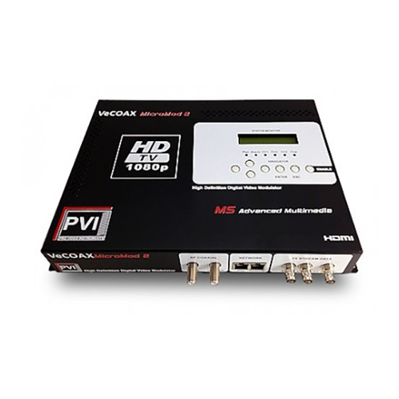
- Page 1 VeCOAX MicroMod-2 2 Channel HD Video RF Modulator REFERENCE GUIDE...
- Page 2 This unit is already pre-configured Follow the quick start points on the next page to operate the unit plug n play There is no need to reset the unit If you reset the unit from the front panel, all settings will be lost, and you will need to set again all the parameters as per this manual.
- Page 3 QUICK START HERE 1) Connect your Video Sources > Front panel Led CH1 CH2 turns on This process is automatic, and there is no setting when you use HDMI or SDI If you want to use other inputs you need to configure the video input first from the web interface as described next on this manual If one of the inputs is not valid or not connected, the ALARM led will turn on The alarm led is one, for all the inputs, and turns on when one input is not valid...
-
Page 4: Tech Support
Tech Support Please read carefully all this manual as it covers ALL and EVERY aspect to set this product as per your needs, using pictures and examples. Should you need any additional support please go to pvisupport.com and open a quick ticket The proper engineer will address your questions very quickly right after you post the ticket Tickets works faster and better than phone calls as the tickets are responded directly from the proper engineers to give you a prompt and best solution. -
Page 5: Audio Video Inputs
AUDIO VIDEO INPUTS: Your unit has 2 independent channels / inputs, each with analog & digital connectors, you can select via software per each of the channels: HDMI Input: Connect your Digital audio/video source with a single HDMI digital cable – For best quality solution NOTE: you can use this port to input Dolby Pass Through stereo / 5.1 / 7.1 Component Input: Connect your RGB analog HD/SD video using the RED GREEN BLUE RCA Composite Input: Connect your CVBS composite SD video using the YELLOW RCA out into the RED RGB input... - Page 6 ASI I/O Ports ( option ): Your unit has 1 ASI Input and 2 ASI Output BNC ports, to add transport stream data from any ASI external source, or to feed any ASI device with the transport stream REMUX generated from the unit Usually the ASI ports are not used.
- Page 7 Easy Setup & Customization to your parameters For an easy and quick configuration of your parameters we suggest to connect a laptop and use the WEB Browser interface The default WEB ADDRESS to enter on the navigation of your web browser is 192.168.0.136 So you need to set first your computer to a valid static network address to communicate to the unit address.
-
Page 8: Select Properties
Select PROPERTIES... - Page 9 Select INTERNET PROTOCOL VERSION 4 - PROPERTIES Select USE FOLLOWING IP ADDRESS and enter the value 192.168.2.100, then ckick OK...
- Page 11 Close all the Network Setup Windows...
-
Page 12: User = Admin
6) Open Internet Explorer or Google Chrome or Firefox browser. In the address field of your browser enter 192.168.2.136 then click enter The Login Splash page should appear, then login with: user = admin password = admin... - Page 13 Video Inputs & Encoders setup On the web interface select INPUT 1 to control the audio video and assignment for channel 1 Copy the values on the picture for the best factory-standard settings When done, Click the APPLY BUTTON to set the parameters...
-
Page 14: Aspect Ratio
Interface = Select the input connector/s you want to use, as HDMI or YPbPr Component or CVBS Composite – default is HDMI PLEASE NOTE: TO CONNECT COMPOSITE VIDEO CONNECT THE YELLOW RCA TO THE RED RGB INPUT. The Yellow is for the closed captioning capture ONLY Video Format = Select between MPEG2 and MPEG4 H264 video compression –... - Page 15 Dialog Normalization = FCC dialog norm value – required for some broadcast transmission – default = -24 Audio Source = Select the input connector for the AUDIO, as HDMI digital or L/R Analog or Optical If you need to feed HDMI video but take the audio from the L/R RCA connectors, switch this to Analog. –...
- Page 16 Second TAB – Encoder Out Parameters Copy the values on the picture for the best factory-standard settings When done, Click the APPLY BUTTON to set the parameters OUT Enable = Map this encoder channel to the wanted Modulator Frequency Output This unit has FOUR frequency modulators ( RF1 / RF2 / RF3 / RF4 ) Each modulator can be turned on or off so you can decide to send out the two encoded channels on one single frequency, or use one frequency per each encoder channel...
- Page 17 Service Provider = The name of the Headend (any id, or the name of the company ). – default = PVI Program Name = This is the Program name you want to assign to this channel - make sure to use different names between the different channels of your unit to avoid conflicts –...
- Page 18 Status Box ( top right ) = Shows the current format for the incoming video and the current encoding bitrate NORM = UNKNOWN > the video is not connected / the video format is invalid / the video is connected to a wrong port respect the one selected.
- Page 19 On the web interface select INPUT 2 to control the audio video and assignment for channel 2 Copy the values on the picture for the best factory-standard settings When done, Click the APPLY BUTTON to set the parameters...
- Page 20 Interface = Select the input connector/s you want to use, as HDMI or YPbPr Component or CVBS Composite – default is HDMI PLEASE NOTE: TO CONNECT COMPOSITE VIDEO CONNECT THE YELLOW RCA TO THE RED RGB INPUT. The Yellow is for the closed captioning capture ONLY Video Format = Select between MPEG2 and MPEG4 H264 video compression –...
- Page 21 Dialog Normalization = FCC dialog norm value – required for some broadcast transmission – default = -24 Audio Source = Select the input connector for the AUDIO, as HDMI digital or L/R Analog or Optical If you need to feed HDMI video but take the audio from the L/R RCA connectors, switch this to Analog. –...
- Page 22 Second TAB – Encoder Out Parameters Copy the values on the picture for the best factory-standard settings When done, Click the APPLY BUTTON to set the parameters OUT Enable = Map this encoder channel to the wanted Modulator Frequency Output This unit has FOUR frequency modulators ( RF1 / RF2 / RF3 / RF4 ) Each modulator can be turned on or off so you can decide to send out the two encoded channels on one single frequency, or use one frequency per each encoder channel...
- Page 23 Service Provider = The name of the Headend (any id, or the name of the company ). – default = PVI Program Name = This is the Program name you want to assign to this channel - make sure to use different names between the different channels of your unit to avoid conflicts –...
- Page 24 Status Box ( top right ) = Shows the current format for the incoming video and the current encoding bitrate NORM = UNKNOWN > the video is not connected / the video format is invalid / the video is connected to a wrong port respect the one selected.
- Page 25 Set the Frequency/Frequencies to send out This unit can output up to 4 adjacent frequencies ( RF1 RF2 RF3 RF4 ) Each frequency can be turned on if something is sent to it from the encoders, usb, or asi, otherwise turned off. Copy the values and selections as on the picture for a perfect operation In this Example, the unit is used for the US American Cable Operation STANDARD...
- Page 26 Set the first RF1 Frequency then click apply, so the following frequencies will be set automatically, spanned of 6 mhz eachother as per the US Cable television standard. In this example we set 195 mhz ( channel 10 over coax ) then we click apply so the RF2 takes automatically the value 201 Mhz ( channel 11 over coax ) the RF3 207 Mhz ( channel 12 over coax ) the RF4 213 Mhz (channel 13 over coax ) It is possible to set the channels leaving interspace channels within a maximum window of 50 mhz between...
- Page 27 IPTV STREAMING OUT Configuration ( option ) If you do not plan to use the IPTV out, skip this step Copy the values and selections as on the picture for a perfect operation NOTE: Some network switches are not configured to pass RTP/RTSP traffic so this might result in disrupting the video streaming.
- Page 28 DATA IP This section sets the Physical ip address of the IPTV Streaming port. The ip port address and the nms port address used for the remote control CANNOT be set to the same network. As example, the Remote control port can be on network 192.168.0.xxx and the IPTV port can be 192.168.3.xxx Should you use multiple units, make sure the mac address is set to a different value between units ( just change the last digit and apply ) Unless required by your application THERE IS NO NEED TO CHANGE THE DATA IP VALUES, as these...
- Page 29 DST PORT = Set the MULTICAST PORT to use for the streaming Default = 2001 SRC PORT = The src port you want to use to find the streams, used on some players Default = 4001 BITRATE = Is the fixed bitrate the MPTS will take on the network ( null stuffing ) Default = 45000 kilobits ( adjust this to match the sum of the two channel bitrates ) = The TTL time the network requires and accepts Default = 128 for the first stream and 128 for the second stream...
- Page 30 TS CONFIG – Descriptors Format Setting The Descriptors ( data sent to the TVs to recognize the channels ) must be set for RF1 RF2 RF3, selecting Modulation mode = 4 and CVCT ( CABLE MODE ), then VCT INSERT selected. Apply and repeat for all RF1 RF2 RF3 ( RF4 AND MPTS ARE NOT USED in this configuration example ) Without this setting some televisions might not recognize the channels as Digital Television Channels.
- Page 31 SAVE / LOAD After the equipment is set, the save operation must be performed so in case of power off the unit will keep the settings On the System menu, select SAVECONFIGURATION > click SET IMPORTANT : The restore configuration and factory set buttons should not be used as it brings the unit in a specific test mode not suitable for the final operation.
- Page 32 UPGRADE Use this interface to load and upgrade the firmware for your unit.
- Page 33 NETWORK Use this function to change the REMOTE CONTROL network address of the unit. WARNING : DO NOT CHANGE THIS PARAMETER UNLESS YOU NEED TO This whole manual refers to the unit default address 192.168.0.136, and if you change your address, please make sure to write it on this manual too, so in future you will be able to recall the current address to point the web browser Improper setting of this parameter might result with loss of control of the unit, and the only solution is the general reset...
- Page 34 LOGIN Use this function to change the USER NAME and PASSWORD to access the system WARNING : DO NOT CHANGE THIS PARAMETER UNLESS YOU NEED TO Improper setting of this parameter might result with loss of control of the unit, and the only solution is the general reset from the physical front panel menu, accessing the menu via front panel button EN/SAVE >...
-
Page 35: Common Troubleshooting
Common Troubleshooting Parameters are set correctly but there are no channels on the out a) POWER OFF / ON and try again b) Check the LEDS CH1 / CH2 are on, if not, check the input video sources and their setting If CH1 or CH2 are off, the TV will not find / store the related channel as the stream is missing c) Test on another television / different brand and model –... - Page 36 NORTH AMERICAN DIGITAL QAM CABLE TELEVISION CHANNELS / FREQUENCIES Channel Number QAM / CDSREF Carrier (MHz) Subband "T" Channels Lowband 57.00 63.00 69.00 75.00 79.00 or 81.00 85.00 or 87.00 Midband 93.00 99.00 105.00 111.00 117.00 Midband 123.00 129.00 135.00 141.00 147.00 153.00...
- Page 37 219.00 225.00 231.00 237.00 243.00 249.00 255.00 261.00 267.00 273.00 279.00 285.00 291.00 297.00 Hyperband 303.00 309.00 315.00 321.00 327.00 333.00 339.00 345.00 351.00 357.00 363.00 369.00 375.00 381.00 387.00 393.00 399.00 405.00 411.00 417.00 423.00 429.00 435.00 441.00 447.00 453.00 459.00...
- Page 38 465.00 Ultraband 471.00 477.00 483.00 489.00 495.00 501.00 507.00 513.00 519.00 525.00 531.00 537.00 543.00 549.00 555.00 561.00 567.00 573.00 579.00 585.00 591.00 597.00 603.00 609.00 615.00 621.00 627.00 633.00 639.00 645.00 Jumboband 651.00 657.00 663.00 669.00 675.00 681.00 687.00 693.00 699.00...
- Page 39 705.00 711.00 717.00 723.00 729.00 735.00 741.00 747.00 753.00 759.00 765.00 771.00 777.00 783.00 789.00 795.00 801.00 807.00 813.00 819.00 825.00 831.00 837.00 843.00 849.00 855.00 861.00 867.00 873.00 879.00 885.00 891.00 897.00 903.00 909.00 915.00 921.00 927.00 933.00 939.00 945.00 951.00...
- Page 40 957.00 963.00 969.00 975.00 981.00 987.00 993.00 999.00...
Need help?
Do you have a question about the VeCOAX MicroMod-2 and is the answer not in the manual?
Questions and answers