Advertisement
Quick Links
1M23N17491
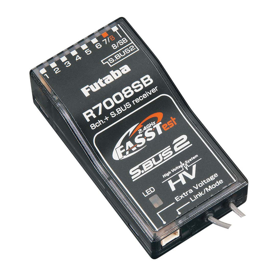
R7008SB
Instruction Manual
FASSTest-2.4GHz Bidirectional
Communication System
S.BUS2 / S.BUS Port and 8 Channels for
Conventional System Receiver
Usage precaution
• Analog servos cannot be used with the
R7008SB in the FASSTest 12CH mode.
• The R7008SB receiver can only be used
with FASSTest capable transmitters.
• Don't connect to Extra Voltage before turn-
ing on a receiver.
WARNING
Changes or modification not expressly
approved by the party responsible for
compliance could void the user's authority
to operate the equipment.
The R7008SB receiver should be protect-
ed from vibration by foam rubber, Velcro
or similar mounting methods. Protect
from moisture.
Keep away from conductive materials to
avoid short circuits.
Antenna installation precaution
Do not cut or bundle the receiver antenna
wire.
Do not bend the coaxial cable. It causes
damage.
The antennas must be mounted in such a
way to assure they are strain relieved.
Compliance Information Statement (for U.S.A.)
This device, trade name Futaba Corporation of America, model number R7008SB, complies with part15 of the
FCC Rules. Operation is subject to the following two conditions:
(1) This device may not cause harmful interference, and
(2) This device must accept any interference received, including interference that may cause undesired operation.
(3) This module meets the requirements for a mobile device that may be used at separation distances of more than
20cm from human body.
To meet the RF exposure requirements of the FCC this device shall not be co-located with another transmitting
device.
The responsible party of this device compliance is: Futaba Service Center 3002 N Apollo Drive Suite 1,
Champaign, IL 61822 U.S.A. TEL (217)398-8970 or E-mail: support@futaba-rc.com (Support)
Thank you for purchasing a Futaba R7008SB FASSTest-
2.4GHz compatible receiver. The R7008SB receiver features bi-
directional communication with a FASSTest Futaba transmitter
using the S.BUS2 port. Using the S.BUS2 port an impressive
array of telemetry sensors may be utilized. It also includes both
standard PWM output ports and S.BUS output ports.
Applicable systems: Futaba FASSTest-2.4GHz
system transmitter
Keep the antenna as far away from the motor,
ESC and other noise sources as you possibly can.
Be sure that the two antennas are placed at 90
degrees to each other.
• The R7008SB has two antennas. In order to maximize signal
reception and promote safe modeling Futaba has adopted a
diversity antenna system. This allows the receiver to obtain
RF signals on both antennas and fly problem-free.
Antenna installation for carbon fuselage
WARNING
You must leave 30mm at the tip of the antenna
fully exposed. The exposed antenna should be
secured so that it cannot move around or back
inside of your aircraft.
S.BUS2 precaution
DANGER
DANGER
Don't connect a connec-
tor, as shown in a before
figure.
• It will short-circuit, if it connected
in this way. A short circuit across
the battery terminals may cause
Do not insert either a switch
or battery in this manner.
abnormal heating, fire and burns.
WARNING
Only S.BUS2 capable devices may be connected
to the S.BUS2 port. Standard S.BUS servos and
gyros should not be connected to the S.BUS2 port.
R7008SB Specifications
FASSTest-2.4GHz system(18CH/12CH mode)/
S.BUS2 and S.BUS port and 8 channels for conven-
tional system receiver
• Dual antenna diversity
• Size: 0.98 x 1.86 x 0.56 in. (24.9 x 47.3 x 14.3 mm)
• Weight: 0.38 oz. (10.9g)
• Power requirement: 3.7V to 7.4V(Voltage range: 3.5 to
8.4V)
• Battery F/S Voltage: It sets up with a transmitter
• Extra Voltage port: 0 ∼ 70V DC
* Be sure that when using ESCs regulated output the capacity of the
ESC must meet your usage condition.
It connects with the
+
battery for power, etc.
External voltage input
cable of an option is
−
used. The voltage of
the battery can be
displayed with a
transmitter.
S.BUS2
(Antenna installation)
90˚
(Typical installation)
Please refer the table below for
LED status vs receiver's condition.
LED Indication
Green
Red
Status
Off
Solid
No signal reception
Solid
Off
Receiving signals
Alternate blink
Unrecoverable error (EEPROM, etc.)
Advertisement

Related Manuals for FUTABA R7008SB


Summary of Contents for FUTABA R7008SB
- Page 1 S.BUS2 port. Compliance Information Statement (for U.S.A.) (Antenna installation) This device, trade name Futaba Corporation of America, model number R7008SB, complies with part15 of the 90˚ Please refer the table below for FCC Rules. Operation is subject to the following two conditions: LED status vs receiver's condition.
- Page 2 Ch output/ Battery terminal The R7008SB is capable of changing its channel allocations as described in the table below. This is especially important when using the receiver in a dual receiver mode. See your transmitter operation manual for complete details on operating in the dual receiver mode.
Need help?
Do you have a question about the R7008SB and is the answer not in the manual?
Questions and answers