
Related Manuals for LEYBOLD PhoeniXL300


Summary of Contents for LEYBOLD PhoeniXL300
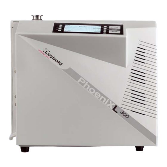
- Page 1 Operating Instructions GA10218_0102 PhoeniXL leak detector catalog-numbers PhoeniXL 250000, 251000 300 dry PhoeniXL 250001, 251001 300 Modul PhoeniXL 250002...
-
Page 2: Table Of Contents
Safety Symbols ....................8 1.1.2 Indications ......................8 1.1.3 Symbols of Vacuum Technology ................ 8 1.1.4 Definiton of Terms ....................9 Support from LEYBOLD Service ............... 10 Introduction ...................... 11 1.3.1 Purpose ......................11 1.3.2 Technical Data PhoeniXL ................12 1.3.2.1 Technical Data .................... - Page 3 Head Installation ......................19 Working Location ..................... 19 Electrical Connections ..................20 2.2.1 Mains Power ....................20 2.2.2 Connections for the Data Acquisition Systems ..........21 2.2.2.1 Option (Accessories) ..................21 2.2.2.2 Digital Out (Control) ..................22 2.2.2.3 Digital In (Control 2) ..................22 2.2.2.4 Recorder ......................
- Page 4 Head 4.1.2.2 START Button ....................34 4.1.2.3 STOP Button ....................34 4.1.2.4 ZERO Button ....................35 4.1.2.5 MENU Button ....................36 4.1.2.6 Soft Keys ......................36 4.1.2.7 Numerical Entries ..................... 36 4.1.3 Vacuum Method ....................38 4.1.4 Partial Flow Method ..................39 4.1.5 Sniffer Mode .....................
- Page 5 Head Mode ....................... 54 Trigger & Alarms ....................55 6.4.1 Trigger Level 1 ....................56 6.4.2 Trigger Level 2 ....................56 6.4.3 Trigger Level 3 ....................56 6.4.4 Units ........................ 56 6.4.5 Volume ......................57 6.4.6 Alarm delay ...................... 58 6.4.7 Audio alarm type ....................
- Page 6 Head 6.6.4.6 Scaling Recorder Output .................. 75 6.6.4.7 PLC Sample Rate ..................... 75 6.6.5 Miscellaneous ....................75 6.6.5.1 Time&Date ....................... 76 6.6.5.2 Language ......................76 6.6.5.3 Calibration request ................... 77 6.6.5.4 Service interval fore pump ................77 6.6.5.5 Service interval exhaust oil filter ............... 77 6.6.5.6 Service message exhaust oil filter ..............
- Page 7 Factor of Calibration - Range of Values ............. 87 Error And Warning Messages ..............88 Hints ........................ 88 List of Errors & Warnings .................. 88 Maintenance ....................95 LEYBOLD Service .................... 95 9.1.1 Maintenance Plan ..................... 95 9.1.2 Opening the PhoeniXL ..................96 9.1.3...
-
Page 8: General Information
Head General Information We recommend that you carefully read this operating instructions to ensure optimum operating conditions right from the start. This Technisches Handbuch contains important informations on the functions, installation, start-up and operation of the PhoeniXL. All the informations in this handbook are based for the PhoeniXL leak 300 dry detector. -
Page 9: Definiton Of Terms
Head 1.1.4 Definiton of Terms The range of the preamplifier and the vacuum ranges are selected auto- Autoranging matically. The autoranging feature of the PhoeniXL covers the entire range or leak rates depending on the selected operating mode. Not only the leak rate signal, but also the pressure in the test sample (inlet pressure P1) and the forevacuum pressure (P2) are used for control purposes. -
Page 10: Support From Leybold Service
Fig. 1 Declaration of contamination form If equipment is returned to Leybold, indicate whether the equipment is free of substances damaging to health or whether it is contaminated. If it is contaminated also indicate the nature of the hazard. For this you must use a form which has been prepared by us which we will provide upon request or you can take from the technical documentation folder. -
Page 11: Introduction
See instructions of the rotary vane pump. If the PhoeniXL will be used in an application with toxic materials please contact Leybold for appropriate decontamination rules. Should the unit will be in contact with dangerous gases, the declaration of contamination has to be filled in. -
Page 12: Technical Data Phoenixl 300
Head 1.3.2 Technical Data PhoeniXL 1.3.2.1 Technical Data Max. inlet pressure 15 mbar Minimum detectable Helium leak rates in vacuum mode ≤5·10 mbar l / s in sniffer mode <1·10 mbar l / s Minimum detectable Hydrogen leak rates in vacuum mode ≤1·10 mbar l / s in sniffer mode... -
Page 13: Other Data
Head 1.3.2.3 Other Data Valves solenoid Dimensions (L × W × H) in mm 495 x 456 x 314 Weight in kg 40.0 Noise level dB (A) < 54 max. Audio alarm dB (A) Contamination level (to IEC 60664-1) Overvoltage category (to IEC 60664-1) 1.3.2.4 Ambient Conditions For use within buildings... -
Page 14: Electrical Data
Head To get down to the minimum detected leak rate range some conditions must be fulfilled: PhoeniXL has to run at least 20 minutes Ambient conditions must be stable (temperature, no vibration/accelera- tions.) The part under test has been evacuated long enough without using the zero function (background is no longer decreasing) ZERO must be active 1.3.3.2... -
Page 15: Technical Data Phoenixl 300 Modul
Head 300 Modul 1.3.4 Technical Data PhoeniXL 1.3.4.1 Technical Data Max. inlet pressure 15 mbar Minimum detectable Helium leak rates in vacuum mode – with Scroll pump ≤ 8·10 mbar l / s – with oil sealed pump ≤ 5·10 mbar l / s in sniffer mode <1·10... -
Page 16: Other Data
Head 1.3.4.3 Other Data Valves solenoid Dimensions (L × W × H) in mm 495 x 456 x 314 Weight in kg 29.5 Noise level dB (A) < 54 max. Audio alarm dB (A) Contamination level (to IEC 60664-1) Overvoltage category (to IEC 60664-1) 1.3.4.4 Ambient Conditions For use within buildings... -
Page 17: Accessories And Options
Head Blank flange DN 25 KF Clamping ring DN 25 KF Centering ring DN 25 KF 1.4.2 Accessories and Options The following parts can be ordered additionally: Sniffer Line SL300 252003 Leak Ware (Software for data aquisation) 14090 Helium Sniffer QUICK-TEST QT100 15594 Remote Control Set consisting of 252002... -
Page 18: Remote Control
Head Options for the sniffer line: Sniffer tip rigid 120 mm 12213 Sniffer tip rigid 385 mm 12215 Sniffer tip flexible 120 mm 12214 Sniffer tip flexible 385 mm 12216 Capillary filter metal ( for rough conditions) 12217 Spare parts for the sniffer line Capillary filter plastic (5 pcs) 20003501 Sinter filter with seal (5 pcs) -
Page 19: Installation
Head Installation Working Location Danger of electrical shock. The PhoeniXL must not be operated Caution while standing in water or when exposed to drip water. The same applies to all other kinds of liquids. Avoid contact with bases, acids or solvents as well as exposure Attention to extreme climatic conditions. -
Page 20: Electrical Connections
Head Electrical Connections 2.2.1 Mains Power Generally the local regulations for electrical connections must be obser- ved. Caution Before connecting the PhoeniXL to the mains you must make sure that the mains voltage rating of the PhoeniXL coincides with the locally available mains voltage. The instrument must exclusi- vely be connected to a single phase supply with fuses for instal- lation (Circuit breaker 10A max. -
Page 21: Connections For The Data Acquisition Systems
10 W. The contacts are numbered from bottom to top. Assignment +24 V, constantly applied, power supply for the Leybold partial flow valve or sniffer line. +24V switched by the PhoeniXL for an external venting... -
Page 22: Digital Out (Control)
Head 2.2.2.2 Digital Out (Control) The following relay outputs Fig. 3/8 are available for further signal proces- sing. The maximum rating for the relay contacts is 60V AC/1A. The contacts are numbered from bottom to top. Assignment PLC in free selectable PLC in free selectable PLC in free selectable 5 to 7... -
Page 23: Recorder
Head 2.2.2.4 Recorder The recorder output Fig. 3/7 may be used to chart the leak rate, the inlet pressure and the forevacuum pressure. Both recorder activities can be adjusted individually for showing leak rates and pressures. The measured values are provided by way of an analogue signal in the range of 0 V …... -
Page 24: Remote Control
Head 2.2.2.6 Remote Control The remote control interface Fig. 3/10 is a serial interface to control the PhoeniXL by the remote control. The remote control can be connected via an extension cable with a RJ45 plug. Refer to the Interface Description for more information. -
Page 25: Connection Of An External Pump
Connection of an external pump (Only 300 Modul PhoeniXL The PhoeniXL300 Modul offers two possibilities to connect the external forevacuum pump to the DN 25 KF flange. One on the side of the PhoeniXL or one in the bottom (measurements see appendix). As default setting the flange on the side is chosen. - Page 26 Head Pressure: mbar Minimum volume: Beep: Maximum evacuation time: 30 minutes Audio Alarm Type: Trigger Alarm Max. pressure limit for sniff mode 0.15 mbar Min. pressure limit for sniff mode 0.05 mbar Control location local Alarm delay: 30 seconds Leak rate filter: auto Zero: enable...
-
Page 27: First Operation Check
Head First Operation Check The steps for an initial operation are described in this chapter. It is explai- ned how to switch on the PhoeniXL, how to measure and how to carry out an internal calibration. If anything unexpected happens during the initial operation or the leak detector acts in a strange way the PhoeniXL can be switched off by the mains switch at any time. -
Page 28: Internal Calibration
Head 5. Press the START Button Fig. 4/10. The inlet will be evacuated and if the inlet pressure drops below 15 mbar a measured leak rate will be dis- played. 6. Press the STOP Button Fig. 4/12, the PhoeniXL will go to Stand-by. If you press STOP a few seconds the inlet of the PhoeniXL will be vented. -
Page 29: Verification With An External Test Leak
Head 3.2.3 Verification with an external test leak To verify the accuracy please proceed through the following steps. A test leak is required. If a test leak is not available please continue with step 21. 10. Remove the blind flange from the inlet port and connect the open helium test leak to the inlet port. -
Page 30: Description And Working Principle
Head Description and Working Principle Introduction The PhoeniXL basically is a helium leak detector for vacuum applications, i.e. the part under test is evacuated while the test is performed. The vacuum is achieved with a pumping system that is part of the PhoeniXL. In addition the vacuum can be generated by pumps which are set up in parallel to the PhoeniXL. - Page 31 Head Pos. Description Fore pressure pump (provides the foreline pressure for the TMP und pumps down the parts under test) Inlet Port Pirani gauge P1 (inlet pressure) V1 … V7: Electromagnetic Valves to control the gas flows The mass spectrometer (MS) is mainly composed of the ion source with cathode, the magnetic separator and the ion collector.
-
Page 32: 300 Modul
Head Diaphragm pump 300 dry Fig. 6 Vacuum diagram PhoeniXL Pos. Description MS: Mass Spectrometer, Helium sensor (180° magnetic field mass spectrometer) Turbomolecular Pump (TMP, provides high vacumm conditions in the MS) Pirani gauge P2 (fore vacuum pressure) Diaphragm pump (provides the foreline pressure for the TMP und pumps down the parts under test) Inlet Port Pirani gauge P1 (inlet pressure) - Page 33 Head external pump 300 Modul Fig. 7 Vacuum diagram PhoeniXL Pos. Description MS: Mass Spectrometer, Helium sensor (180° magnetic field mass spectrometer) Turbomolecular Pump (TMP, provides high vacumm conditions in the MS) Pirani gauge P2 (forevacuum pressure) Fore pressure pump (provides the foreline pressure for the TMP und pumps down the parts under test) Inlet Port Pirani gauge P1 (inlet pressure)
-
Page 34: Control Panel
Head 4.1.2 Control Panel Control Panel Fig. 8 contains a liquid chrystal display (LC Display), the START, STOP, ZERO and MENU buttons and eight soft Keys for the diffe- rent menus and inputs selections. Fig. 8 Control Panel Pos. Description Pos. -
Page 35: Zero Button
Head 4.1.2.4 ZERO Button Pushing the ZERO Button Fig. 8/11 enables the zero mode. (see also Chapter 4.1.6) When pressing ZERO the currently measured leak rate is taken as a back- ground signal and is subtracted from all further measurements. As a result the displayed leak rate then is mbarl/s in GROSS 1·10... -
Page 36: Menu Button
Head When you want to see the measurement signal (including underground) please press the ZERO button again. The saved value will be reset to zero. The underground signal will not be suppressed anymore (Fig. 10). 4.1.2.5 MENU Button When pressing the MENU button (Fig. - Page 37 Head Fig. 11 Numerical entry of the Trigger Level, sample of the digit In the submenu press 3 (Soft Key no. 4) Fig. 12 Fig. 12 Trigger Level, change of the first digit ⏐ GA10218_0101 - 5/2002...
-
Page 38: Vacuum Method
Head 4.1.3 Vacuum Method For the purpose of leak detection on a test sample (vacuum method), the sample has to be evacuated so that Helium or Hydrogen which is sprayed on to the outside, can enter through any leaks due to the pressure diffe- rential for detection by the PhoeniXL. -
Page 39: Partial Flow Method
Alternatively to a partial flow pump set an external auxiliary pump may also be connected via a tee, this option is possible for the PhoeniXL300 dry and PhoeniXL300 Modul also. However, in such a case the PhoeniXL will not be able to make measurements already at an inlet pressure of 1000 mbar. -
Page 40: Controls On The Remote Control (Optional)
Head 4.1.6 Controls on the Remote Control (Optio- nal) Fig. 13 View of remote control ZERO button Scale for the pressure in STOP / VENT button the test sample START button Exponent LED Bargraph display LED Lock Underflow display Acoustic signal quiter (under range) Acoustic signal louder Leak rate scale... - Page 41 Head level is taken over anew, provided the PhoeniXL has been running in the Standby or Vent status for at least 20s. The STOP/VENT-button has two different fuctions, depending on how STOP / VENT-button long it is pressed: STOP function Based on the measurement mode of the PhoeniXL, a brief press of the STOP-button interrupts the evacuation process of the test sample and the measurement mode is interrupted.
-
Page 42: Displays On The Remote Control
Head rently measured value as the “zero level”. However, the internal zero level setting as in use remains unchanged. After operating the zero button, only that amount of the currently measu- red value is substracted so that the display limit is just reached. The dis- played results of a leak rate measurement will be too high by an amunt which corresponds to the display limit. -
Page 43: Operation Of The Phoenixl
Head Operation of the PhoeniXL The PhoeniXL is switched on by pushing the mains switch (Please refer to Chapter 3.2.1). After about 2 minutes the run-up procedure is finished; the unit is in Stand-by-mode and ready to measure. 300 Modul When using the PheoniXL an additional forevacuum pump (dry or wet version) has to be connected to the forevacuum connection (DN25... -
Page 44: Display In Stand-By Mode
After 20 minutes the machine closes the gas ballast valve automatically to limit the loss of oil. This function can be chosen automatically for the PhoeniXL300 dry and PhoeniXL300 Modul. Every time the unit changes into stand-by mode it can start automatically after 20 seconds. -
Page 45: Call For Calibration
Head Fig. 14 Display: Measurement Mode with bargraph 5.4.1 Call for Calibration In all modes the Soft Key no. 5 is used to get to the calibration routine. Refer to Chapter 7 Calibration for further information regarding calibration. 5.4.2 Speaker Volume On the left hand side two loud speaker symbols are shown, combined with the signs + and - (Fig. -
Page 46: Measurement Mode With Bargraph
Head Symbol of display Meaning Explanation ZERO ZERO Indicates if ZERO-function is active. 5.4.4 Measurement Mode with bargraph The display shows the leak rate in big digital figures, see Fig. 14. The unit of the leak rate is shown, too. Underneath the leak rate the inlet pressure is displayed in smaller digits. -
Page 47: Description Of The Menu
Head Description of the Menu By pressing the MENU push button Fig. 8/13 the main menu will be dis- played regardless of the current working mode or status of the PhoeniXL The main menu Fig. 16 leads the operator to several submenus described in the following chapters. - Page 48 Head 1. Level 2. Level 3. Level View Scale linear/logarithmic Display-range auto/manual Time axis Contrast Background in Stand-by Lower display limit Mode Sniff/Vacuum Trigger & Alarms Trigger Level 1 Trigger Level 2 Trigger Level 3 Units Volume Alarm delay Audio alarm type Calibration internal external...
-
Page 49: View
Head Explanation to figure 16: Key No. Name Description Back Return to the previous screen. View Display settings like scaling, contrast, system background. Please refer to Chapter 6.2. Mode Selection of the working modes Vacuum or Sniff Please refer to Chapter 6.3. Trigger &... -
Page 50: Scale Linear/Logarithmic
Head Explanation to Fig. 18: Key No. Name Description Back Return to the main menu. Scale linear/logarithmic Settings for bargraph and trend mode. Please refer to Chapter 6.2.1. Display-range auto/ Manual or automatic scaling. Please manual refer to Chapter 6.2.2 Time axis Time axis in trend. -
Page 51: Display-Range Auto/Manual
Head 6.2.2 Display-range auto/manual Main menu > View > Display-range auto/manual The upper limit of the displayed leak rate range can be set manually or automatically. These settings apply to the bargraph ( = bar underneath the digital figures in the measurement mode and y-axis in the trend mode). With the upper limit defined here the lower limit is set to a value based on the number of decades (See Chapter 6.2.1 Scale... -
Page 52: Contrast
Head 6.2.4 Contrast Main menu > View > Contrast The contrast of the display can be changed. The recommended value under regular conditions is about 50 (Default setting). Softkey 3: ↓ Fade the contrast to dark. The minimum values is 0. Softkey 4: Invert display Invert the contrast of the screen, that means background dark and font... -
Page 53: Lower Display Limit
Head the net leak rate from the part under test is measured. When switched to Stand-by / Vent again a new internal background is cal- culated after 25 s. The updated value is underlined. This means that if you press START when the value is underlined, the actual background signal will be subtracted. -
Page 54: Trigger & Alarms
Head Explanation to Fig. 19: Key No. Name Description Cancel Return to the main menu without any chan- ges of the present settings. Sniff The sniffer mode will be used. Vacuum The vacuum mode will be used. Save the settings and return to the previous menu. -
Page 55: Trigger Level 1
Head 6.4.1 Trigger Level 1 Main menu > Trigger & Alarms > Trigger Level 1 The value of the first trigger level can be set. See Chapter 4.1.2.7 Numeri- cal Entries for the description of the entry. Trigger 1, 2 and Trigger 3 are programmable switching thresholds. When these thresholds will be exceeded the PhoeniXL reacts as follows: In the status line of the display the signs for Trigger 1, 2 and Trigger 3 are Display... -
Page 56: Volume
Head ↑ Softkey 2: Scroll up to select a pressure unit. ↓ Softkey 3: Scroll down to select a pressure unit. ↑ Softkey 6: Scroll up to select a leak rate unit. Softkey 7: ↓ Scroll down to select a leak rate unit. 6.4.5 Volume Main menu... -
Page 57: Alarm Delay
Head 6.4.6 Alarm delay Main menu > Trigger & Alarms > Alarm delay In some applications (for instance during pump down in a „chamber test system“) it might be necessary to block an alarm for some time after pres- sing START. This delay time of the alarm can be changed. -
Page 58: Pinpoint
Head 6.4.7.1 Pinpoint The tone of the acustical signal changes its frequency only in a Leakrate- window Fig. 21 which ranges from one decade below the Trigger level 1 up to one decade above the Trigger level 1. Below the window the tone is constantly low, above the window it is constantly high. -
Page 59: Calibration
Head Calibration Main menu > Calibration In the menu Calibration Fig. 23 the selection between internal and external calibration can be chosen. 7 Calibration for a detailed description of the calibra- Please refer to Chapter tion. Fig. 23 Display: Calibration Menu ⏐... -
Page 60: Settings
Head Settings Main menu > Settings This menu Fig. 24 allows to observe and to change the adjustment of the internal machine settings. Fig. 24 Display: Settings Menu Explanation for Fig. 24: Key No. Name Description Back Return to the main menu. Vacuum settings Settings of vacuum system related functions. -
Page 61: Vacuum Settings
Head 6.6.1 Vacuum settings Main menu > Settings > Vacuum settings This menu allows to observe and to change the settings belonging to the vacuum system. Softkey 3: Vent delay Refer to chapter 6.6.1.2 Softkey 4: Vacuum ranges Refer to chapter 6.6.1.3 Softkey 5: Partial flow setup... -
Page 62: Automatic Purge
Head 300 Modul The menu for the PhoeniXL version allows the following vacuum settings which varies to the PhoeniXL Softkey 2: Automatic purge Refer to chapter 6.6.1.1 Softkey 3: Vent delay Refer to chapter 6.6.1.2 Softkey 4: Vacuum ranges Refer to chapter 6.6.1.3 Softkey 5: Forepump set up... -
Page 63: Vacuum Ranges
Head Softkey 2: Immediately The inlet port will be vented immediately after pressing the STOP button. Softkey 3: After 1 second The inlet port will be vented with a time delay of 1 second. Softkey 4: After 1.5 seconds The inlet port will be vented with a time delay of 1.5 second. Softkey 5: Help Softkey 6:... -
Page 64: Partial Flow Setup
Head 300 dry The PhoeniXL allows the vacuum ranges as follows: Softkey No. 2: GROSS only 300 dry In this mode the PhoeniXL remains at the inlet flange after falling below 15 mbar. When the pressure is increasing over 15 mbar the 300 dry PhoeniXL switches automatically into evacuation mode. - Page 65 Head ↓ Softkey 2: The entry of the nominal pumping speed of the partial flow pump can be decreased. The minimum pumping speed is 4m ↓ Softkey 3: Decrease Quick-pump time. The quick-pump time defines whether and how long valve V10 of the partial flow block is opened. (For detailed des- criptions please refer to the operating instructions “GA 10.277”...
-
Page 66: Sniffer Factor
Head 300 Modul Fore pump for the PhoeniXL ↓ Softkey 2: The entry of the nominal pumping speed of the partial flow pump can be decreased. The minimum pumping speed is 4 m Softkey 3: Fore pump type 300 Modul The PhoeniXL can be operated with a dry fore pump (for ex. -
Page 67: Leak Rate Internal Test Leak
Head Since the effective pumping rates are usually not known due to the con- ductances of the vacuum connections, we recommend the following indi- rect measurement: 1. Set up the PhoeniXL for operation 2. First an internal calibration must be performed with machine factor = 1 (Refer to Chapter 7) 3. -
Page 68: Calculate Inlet Area Background
Head 6.6.2.1 Calculate inlet area background Main menu > Settings > Filter & Background > Calculate inlet area background This function calculates the background of the inlet area. The PhoeniXL has to be in the following conditions: 1. Mode vacuum 2. -
Page 69: Mass
Head 6.6.3 Mass Main menu > Settings > Mass The requested mass of the measured gas can be selected. The PhoeniXL must be in stand-by for changing to another mass. Softkey 2: H (2 amu) Hydrogen with the mass of 2 amu will be measured. Softkey 3: He (3 amu) Isotop of helium with the mass of 3 amu will be measured. -
Page 70: Define Recorder Output
Head The PhoeniXL is controlled via the Digital In connector or/and the START, STOP and ZERO buttons at the control panel and remote control. Softkey 7: Local The PhoeniXL is controlled via the START, STOP and ZERO buttons at the control panel or remote control. This is the default setting. 6.6.4.2 Define recorder output Main menu... -
Page 71: Rs232
Head The fundamental output voltage is scaled logarithmic. The voltage output ranges from 1 to 10 V with adjustable steps of 0,5 to 10 V per decade (Fig. Fig. 26 Example of range of leak rate, log. 0.5 V/decade 6.6.4.3 RS232 Main menu >... -
Page 72: Define Plc Inputs
Head Description of the operation mode of the Digital Out. The pin assignement for contacts 8 to 16 follows the same order as for pins 5 to 7. The actual pin setting can be seen under Info/View internal data/page 7. The following digital out signals are selectable. - Page 73 Head Description of operation mode of the Digital In. The PLC inputs are working only if the correct location of control has been set (see 6.6.4.1) The actual pin setting can be seen under Info/View internal data/page8. Zero: Change from low to high: activate zero Change from high to low: deactivate zero Start: Change from low to high: activate START...
-
Page 74: Scaling Recorder Output
Head 6.6.4.6 Scaling Recorder Output Main menu > Settings > Interfaces > Scaling Recorder Output Here the scaling of the recorder output can be adjusted. This adjustment is possible with only when the signal LR lin or LR log is chosen. Softkey 2: Decrease the decade The decade of the upper leakrate can be decreased... -
Page 75: Time&Date
Head Softkey 2: Time&Date See chapter 6.6.5.1 Softkey 3: Language See chapter 6.6.5.2 Softkey 4: Calibration request See chapter 6.6.5.3 Softkey 5 Service interval fore pump See chapter 6.6.5.4 Softkey 7: Service interval oil filter See chapter 6.6.5.5 Softkey 8: Service message oil filter See chapter 6.6.5.6 6.6.5.1... -
Page 76: Calibration Request
Head 6.6.5.3 Calibration request Main menu > Settings > Miscellaneous > Calibration request It can be selected whether the operator is reminded of the fact that a cali- bration may has become necessary or not. The default value is off. Softkey 3: The calibration request will be switched off. -
Page 77: Service Message Exhaust Oil Filter
Head ↓ Softkey 3: Decrease of the service intervall steps of within 500 hours. The limit is 1000 hours Softkey 5: Help text ↑ Softkey 7: Increase of the service intervall within steps of 500 hours. The limit is 4000 hours. 6.6.5.6 Service message exhaust oil filter Main menu >... -
Page 78: Load Parameter Set
Head 6.6.6.1 Load parameter set Main menu > Settings > Parameter save / load > Load Para set Save the current parameter settings. Softkey 4: Edit a file name Rename the parameter set. Softkey 8: Save the edited parameter set. 6.6.6.2 Save parameter set Main menu... -
Page 79: Pressure Limits For Sniff Mode
Head ↓ Softkey No. 2: Decrease change over threshold EVAC-GROSS Chosable between15-3 mbar (Default value 15 mbar) ↓ Softkey No. 3: Decrease change over threshold GROSS-FINE Chosable between 0,2-0,05 mbar (Default value0, 2 mbar). Softkey No. 4 Adjustment for ARGON Selection between air or Argon Softkey No. -
Page 80: Maximum Evacuation Time
Head 6.6.7.3 Maximum evacuation time Main menu > Settings > Monitoring functions > Maximum evacuation time This menu item is used to define when the gross leak message is to occur. The gross leak detection process operates in two steps and the limits can be adapted as required. -
Page 81: Information
Head Information Main menu > Information Information Menu Fig. 27 enables submenus to select different kinds of information belonging to the PhoeniXL. Fig. 27 Display: Information Menu Softkey 2: View settings The current settings will be displayed on 5 pages, e.g. trigger levels, test leak mass, date and time. -
Page 82: Access Control
Head Access Control Main menu > Access Control With this menu you can deny or allow access to specific functions of the PhoeniXL Fig. 28 Display: Access Control Menu Softkey 3 Access to Zero function See chapter 6.8.1 Softkey 4: Access to CAL function See chapter 6.8.2 Softkey 8:... -
Page 83: Change Menu-Pin
Head 6.8.2 Change Menu-PIN Main menu > Access Control > Change Menu-PIN The access to the menu can be restricted by entering or changing the per- sonal identification number (PIN). No PIN will be checked if 0000 is entered. The default setting for the Pin is 0013. 4.1.2.7 Numerical Entries for the description of the Please refer to Chapter... -
Page 84: Calibration
Head Calibration Introduction The PhoeniXL can be calibrated in two different ways: Internal calibration by means of a built-in test leak. External calibration by means of an additional test leak which then is attached to the inlet port or the component under test. During the calibration procedure the mass spectrometer is tuned to the maximum helium or hydrogen signal and this signal is referred to the known leak rate of the internal or external test leak. - Page 85 Head After External Calibration ( Fig. 23, Soft Key no. 8) has been chosen the following messages are displayed and the described actions are required: Make sure that the correct mass is selec- ted. Make sure that the test leak is connected and opened.
-
Page 86: Factor Of Calibration - Range Of Values
Head The bargraph display shows a signal which must not decrease any more. There might be a small fluctuation which is okay. If so please press OK (Soft Key no. 8). Fig. 33 Display: External Calibration, Step 5 When signal is stable confirm with o.k. -
Page 87: Error And Warning Messages
Head Error And Warning Messages he PhoeniXL is equipped with a comprehensive self-diagnostic facilities. If an error or warning condition is detected it is indicated via the LC display to the operator. An audio signal is generated when an error or warning occurs. The fre- quency changes every 400 ms from 500 Hz to 1200 Hz and vice versa so that the signal stands out well from ambient noises normally encountered. - Page 88 W21 EEPROM write time out EEPROM defective MC 68 defective W22 EEPROM parameter queue Software problrem, please contact Leybold service. overflow E23 24V for external output 1 is The 24 V voltage for the external output 1 is too high too high.
- Page 89 Head Displayed Message Description and possible solutions E36 Anode-cathode voltage is too Anode-cathode voltage is < 30 V. low. MSV board is faulty. Fuse F4 on MSV board has blown. E37 Suppressor voltage reference Signal MFSZH on MSV board is active. Suppressor signal command value too high! variable is too high.
- Page 90 Drive electronics Turbo Drive S is defective. E51 Unknown TMP error The frequency converter Turbo Drive S indicates an unknown error code. Inform Leybold service E52 TMP frequency is too low! TMP frequency is too low! Frequency converter is faulty.
- Page 91 Check to see if the connecting cable is undamaged, exchange if cable required. Inform Leybold service in case of short circuit in TMP motor E68 TMP error: temperature con- Maximum temperature for the converter has been exceeded. verter too high (>75°C)
- Page 92 Forevacuum or high-vacuum pressure to high: see chapter 6.6.7.1 to reduce the inlet pressure of the PhoeniXL Bearing defective: Inform Leybold service for repair E70 TMP error: TMP motor tempe- Max. motor temperature has been exceeded.
- Page 93 Head Displayed Message Description and possible solutions W81 CAL Factor too low The calculated factor falls out of the valid range (<0,1). The old factor is retained. Possible fault cause: The conditions for calibration have not been maintained. The leak rate of the internal calibrated leak which was entered is much too small.
-
Page 94: Maintenance
Maintenance LEYBOLD Service If equipment is returned to Leybold, indicate whether the equipment is free of substances damaging on health or whether it is contaminated. If it is contaminated also indicate the nature of the hazard. For this you must use a Declaration of Contamination form Fig. -
Page 95: Opening The Phoenixl
Head 9.1.2 Opening the PhoeniXL Fig. 36 Backview of PhoeniXL 1: Openings for removal of the cover for the mechanical section 2: Four screws for loosening the cover for the electronics section. 3: Mechanical cover 4: Electronic cover 1. Switch the PhoeniXL off. 2. -
Page 96: Exchanging The Filter Mats
Head remove it to the front. 8. Removing the cover for the electronics section by removing the four Phillips screws (see Fig. 36/2). 9. Pull the cover over the electronics section back to the rear and place it aside. 10. After completion of all maintenance work put the electronic cover back in place and screw it tighten. -
Page 97: Cleaning
Head regulations for the safety of the environment. The oil change procedure are described in the corresponding Operating Instructions GA 01.601 and these must be foolowed closely. As already stated in Chapter 9.1.1 only Arctic oil must be used for the Tri- vac D 2,5E pump in the PhoeniXL. - Page 98 Head 4. Exchange fuses As can be seen in Fig 37, fuses 1, 2, 3 and 4 are located on the MSV board, fuses 5 and 6 on the I/O board and the fuses 7, 8, 9 and 10 are located on the wiring backplane under the MSV board.
-
Page 99: Exhaust Oil Filter
8. Finally re-install the cover for the mechanical section. Turbo molecular pump For the Leybold turbo molecular pump TW 70 LS it is recommended to change the bearings after 20.000 running hours. For details please refer to the corresponding manual of the turbo pump ( GA 05156.0101) or contact your local Leybold service. -
Page 100: Tecnical Data
Head 9.3.1 Tecnical Data Nominal calibration range mbarl / s Tolerance of nominal calibration range +/- 15 % Temperature coefficient < 0,5 % / °C Leak type Kapillare Filling Helium 9.3.2 Factory Inspection Calibrated leaks are not subject to wear and the Helium loss of the cali- brated leak TL7, being less than 2 % per year, is negligible. -
Page 101: Appendix
Appendix Appendix Ambient Conditions Numerical Entries Autoranging Opening the PhoeniXL Background in Stand-by Partial Flow Method Calibrated leak TL7 Partial flow setup Calibration Partial flow system Calibration request precision Control Panel Remote control Define PLC inputs RS232 Define PLC outputs Define recorder output Settings Sniffer line SL300... - Page 102 Head Abmaße PhoeniXL Familie in mm und inch. (in Klammern) Dimensions PhoeniXL family in mm and inches (in brackets).. Fig. 1 Dimensons Side View ⏐ GA10218_0101 - 9/2002...
- Page 103 Head Abmessungen PhoeniXL Familie in mm und inch. (in Klammern) Dimensions PhoeniXL family in mm and inches (in brackets) Fig. 2 Dimensions Side View ⏐ GA10218_0101 - 9/2002...
- Page 104 Head Abmessungen PhoeniXL in mm 300 Modul und inch (in Klammern). Dimensions PhoeniXL in mm and inches (in Modul brackets). Modul Fig. 3 Dimensions PhoeniXL ⏐ GA10218_0101 - 9/2002...
- Page 105 Head Fig. 4 Declaration of Conformance ⏐ GA10218_0101 - 9/2002...
- Page 106 Head ⏐ GA10218_0101 - 9/2002...
- Page 107 Head ⏐ GA10218_0101 - 9/2002...
Need help?
Do you have a question about the PhoeniXL300 and is the answer not in the manual?
Questions and answers