Rotel RB-1080 Technical Manual
Hide thumbs
Also See for RB-1080:
- Owner's manual (34 pages) ,
- Owner's manual (34 pages) ,
- Owner's manual (10 pages)
Advertisement
T echnical
Manual
Table of Contents
Specification..................................... 1
Parts List .......................................... 2,3
Adjustment....................................... 3
Case Outlines................................... 3
Note On Safety................................. 4
PCB Assembly ................................. 4,6
Schematic Diagram.......................... 7,8
Specification
Continuous Power Output
Total Harmonic Distortion
Intermodulation Distortion
Frequency Response
Damping Factor
Speaker Impedance
Signal to Noise Ratio
Input Impedance/Sensitivity
(XLR Inputs)
Power Requirements
Power Consumption
Dimensions
Weight
SHINSEN-BLD. 4F 10-10 SHINSEN-CHO, SHIBUYA-KU,
TOKYO 150-0045, JAPAN
Quality Uncompromised
(20-20 kHz, ≤ 0.03%, 8 ohms)
(20-20 kHz, ≤ 0.05%, 4 ohms)
(20 Hz-20 kHz, 8 ohms)
(60 Hz: 7 kHz, 4:1)
(20-20,000 Hz, 8 ohms)
(IHF A network)
(RCA Inputs)
(W, H, D)
(net)
®
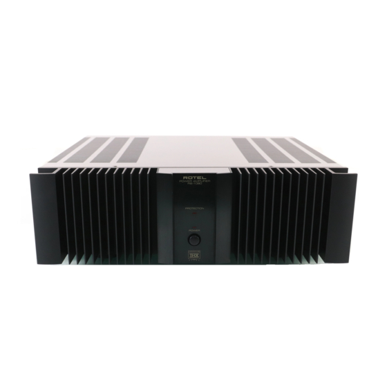
STEREO POWER AMPLIFIER
RB-1080
200 watts/ch.
300 watts/ch.
≤ 0.03%
≤ 0.03%
≥ 10-100,000 Hz, ± 1 dB
≥ 500
4-16 ohms
120 dB
33 k Ohms/1.0 volt
33k Ohms/1.0 volt
115 Volts, 60 Hz or
230 Volts, 50 Hz
550 Watts
440 x 127 x 385 mm
17.38 x 4.76 x 15.16" inches
16.7 kg., 36.74 lb.
Serial. NO.
Begining
Y-337A-00125M/S-S
Advertisement
Table of Contents

Related Manuals for Rotel RB-1080


Summary of Contents for Rotel RB-1080
-
Page 1: Table Of Contents
Quality Uncompromised ® T echnical STEREO POWER AMPLIFIER RB-1080 Manual Table of Contents Specification........1 Parts List .......... 2,3 Adjustment........3 Case Outlines........3 Note On Safety......... 4 PCB Assembly ......... 4,6 Schematic Diagram......7,8 Specification (20-20 kHz, ≤ 0.03%, 8 ohms) Continuous Power Output 200 watts/ch. -
Page 2: Parts List
Parts List-1 SYMBOL PARTS NO. DESCRIPTION SYMBOL PARTS NO. DESCRIPTION X-1177-01,02 PCB ASSY C601.602 041 50BGF4R7M CAPACITOR ELEC.50V4.7UF C804 041 UTES2A220-FB ※ CAPACITOR ELEC.100V22UF C603.604 044 TFKP2-2A681H CAPACITOR FILM 100V680PF D801 034 T1N4148-86 DIODE C607.608 041 25BGF100M CAPACITOR ELEC.25V100UF D802 034 RD10EB ZENER DIODE C609.610... -
Page 3: Adjustment
Parts List-2 SYMBOL PARTS NO. DESCRIPTION SYMBOL PARTS NO. DESCRIPTION X-1291-02 PCB ASSEMBLY D103.104 034 T1N4148-86 DIODE 015 RP-381 REAR CHASSIS D105 034 TRD12JST1 ZENER DIODE 019 4TSH-19#2 PLASTIC FOOT 50F D106 034 T1N4148-86 DIODE 022 T-1037W04 ※ POWER TRANSFORMER IC101 031 PC817B PHOTO COUPLER... -
Page 4: Note On Safety
PCB Assembly Service Note Cautions during Inspection and Repair 1. Keep in mind the safety warnings The safety instructions are shown as the labels or printings on the exterior, the inside chassis or the parts, etc. Refer to the instructions when proceeding with inspection or repair. - Page 5 PCB Assembly...
-
Page 6: Schematic Diagram
Schematic Diagram...
Need help?
Do you have a question about the RB-1080 and is the answer not in the manual?
Questions and answers