Table of Contents
Advertisement
Advertisement
Table of Contents

Related Manuals for cobas h 232


Summary of Contents for cobas h 232
- Page 1 232 Operator’s Manual...
- Page 2 Manual version Revision date Changes Version 1.0 2016-10 New document with country-specific information on Cleaning and Disinfection (based on International Operator’s Manual 0 7469101001 (02) 2016-06 EN). Version 1.1 2017-11 Update: Added Super Sani-Cloth Germicidal Disposable Wipes as recommended disinfect- ing agent;...
- Page 3 232 Operator’s Manual Version 1.1 0 7886594001 (02) 2017-11 EN-CAN...
- Page 4 Roche Diagnostics. Please send questions or comments about this manual to your local Roche representative. ROCHE CARDIAC, COBAS, COBAS H and IQC are trademarks of Roche. The Wi-Fi CERTIFIED Logo is a certification mark of the Wi-Fi Alliance.
- Page 5 This device complies with Part 15 of the FCC Rules and with RSS-210 of Industry Canada For other WLAN certifications, see label on bottom of battery compartment and addendum for information on WLAN registration. The user is fully responsible for the installation, use and upkeep of the cobas h 232 meter.
- Page 6 This page intentionally left blank.
-
Page 7: Table Of Contents
Table of Contents Introduction The cobas h 232 meter......................... 11 Test principle ............................. 13 Contents of the Pack ........................13 1.1 Important safety instructions and additional information............14 Safety information ........................... 15 Disposal of the system ........................17 Battery pack ............................17 General care............................ - Page 8 Table of Contents 3.4 Lockout setup ............................96 Operator lockout..........................97 Quality control (QC) settings ....................100 Quality control (QC) lockout ..................... 102 Instrument quality control (IQC) lockout................104 QC result format ..........................105 Custom Range Troponin T ......................106 Reset test parameters........................
- Page 9 Table of Contents Maintenance and Care 8.1 Conditions for storage and shipping ..................... 169 Storage.............................. 169 Shipping............................170 8.2 Cleaning and disinfecting the meter ..................... 171 Difference between cleaning and disinfecting..............171 When should the meter be cleaned and disinfected? ............ 171 What to clean and disinfect? ....................
- Page 10 Table of Contents This page intentionally left blank.
-
Page 11: Introduction
Readings may be carried out directly where the blood samples are taken. Therefore, the cobas h 232 meter is ideal for use at the point of care in emergency rooms, intensive care units and ambulances, as well as by cardiologists and general practitioners. The cobas h 232 meter is rapid and easy to operate: Insert an unused strip in the meter and apply the sample. - Page 12 Read this operator's manual, as well as the package inserts for all relevant consumables, before using the system for the first time. You must configure the cobas h 232 meter according to your needs before initial use. Refer to Chapter 3, “Meter Setup”. Be sure to read the “Important safety instructions and additional information”...
-
Page 13: Test Principle
Two lines (signal and control line) in the detection zone of the test strip indicate whether the analyte to be determined is present in the sample material. These lines are detected by the cobas h 232 meter with the help of an LED (lighting the detection zone) and a camera sensor (imaging the detection zone). -
Page 14: Important Safety Instructions And Additional Information
1.1 Important safety instructions and additional information This section explains how safety-related messages and information related to the proper handling of the system are presented in the cobas h 232 Operator’s Manual. Please read these passages carefully. The safety alert symbol alone (without a signal word) promotes aware- ness to hazards which are generic or directs the reader to related safety information. -
Page 15: Safety Information
Operators need to adhere to Standard Precautions when handling or using the cobas h 232 meter. All parts of this system should be considered potentially infectious and are capable of transmitting blood-borne pathogens between patients and between patients and healthcare professionals. - Page 16 Do not short circuit the power supply unit, the handheld base unit ■ contacts, or the battery pack. Do not drop the cobas h 232 meter, the power supply unit, or the ■ battery pack and protect these against shaking and vibrations.
-
Page 17: Disposal Of The System
Introduction Disposal of the system Infection by a potentially biohazardous instrument The cobas h 232 meter or its components must be treated as potentially WARNING biohazardous waste. Decontamination (i.e., a combination of processes including cleaning, disinfection and/or sterilization) is required before reuse, recycling, or disposal. - Page 18 Do not place either the battery pack or the cobas h 232 meter on or ■ in heating appliances, such as a microwave, conventional oven, or radiator.
-
Page 19: General Care
Introduction Observe the following general safety instructions for handling the battery pack: Disposal of used battery packs Do not dispose of the battery pack with normal domestic waste. Dispose of used battery packs in accordance with applicable local regulations and directives and your facility’s guidelines on the disposal of electronic waste equipment. -
Page 20: Electromagnetic Interference
Introduction Electromagnetic interference The meter fulfills the IEC 61326-2-6 requirements for emitted interference and interference immunity. Do not use the meter near strong electromagnetic fields, which could interfere with the proper operation of the meter. Electrostatic discharges may cause malfunction of the meter. Touchscreen NOTICE Use only your finger (even when wearing gloves) or special pens... - Page 21 ID longer than four characters. ■ To ensure that your cobas h 232 meter functions properly, observe the operating and storage conditions as given in the chapter “General Product Specifications”, starting on page 183.
-
Page 22: Wireless Connectivity
This feature must be configured by the system administrator. Observe the guidelines of your facility for using wireless local area network connections. For a description of the cobas h 232 meter’s ability to connect to Wireless Local Area Networks (WLAN, Wi-Fi), see appendix B. - Page 23 Introduction The cobas h 232 system complies with FCC radiation exposure limits set forth for an uncon- trolled environment. This equipment should be installed and operated with minimum distance of 20 cm (8 inches) between the radiator and your body.
-
Page 24: Overview Of The Meter And Its Accessories
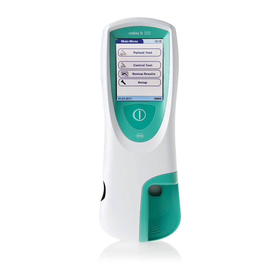
Introduction 1.2 Overview of the meter and its accessories Meter... - Page 25 Introduction Touchscreen Barcode scanner Shows results, information, icons and Operator and patient IDs can be read into results saved in the memory. To select an the meter using the integrated barcode option, simply touch the button lightly. scanner. * On/Off button Battery compartment cover Press this button to power the meter on or Remove to insert the battery pack.
- Page 26 Introduction Test strip guide Code chip slot Insert the test strip here. Insert the code chip here. Infrared (IR) window Charging terminals Supports data communication with the Used for power supply and/or charging (optional) Handheld Base Unit. Covered the battery pack when the meter is by the semi-transparent rear panel.
-
Page 27: Power Supply
Introduction Power supply Universal Battery Pack Power adapter Powers the device. Powers the device and charges the battery pack. The meter can be operated with the rechargeable battery pack only or together with the power adapter or the (optional) Handheld Base Unit, which both charge the battery pack when inserted. Insert the battery pack even when always using the power adapter or the Handheld Base Unit. - Page 28 Introduction During battery operation, the meter always 09:15 am Main Menu displays the power level of the battery pack. The battery icon is divided into four segments which correspond to the battery power level. Patient Test When replacing the battery pack, insert the new battery pack within 24 hours of removing Control Test the old one.
-
Page 29: Test Strip
Introduction Test strip Test area Barcode This area is evaluated by the meter via the Assigns the strip to the corresponding camera. code chip. The barcode is automatically read by the meter when the strip is Sample application area inserted into the test strip guide. The sample is applied to this area after Code chip inserting the test strip in the meter. -
Page 30: Handheld Base Unit
Extension piece The switch sets the mode of operation for For cobas h 232 meter, optional. the Handheld Base Unit. The Handheld Base Unit can be ordered separately. For detailed information on usage and configuration please consult the operator's manual of the Handheld Base Unit and the... -
Page 31: Overview Of The Buttons And Icons Used On Screen
Introduction 1.3 Overview of the Buttons and Icons used on Screen The buttons and icons that appear during normal operation are shown here, along with a general explanation. Error messages and the description of the icons linked to them are provided in a separate chapter. - Page 32 Introduction Button/Icon Meaning Apply QC sample (the time left to apply sample is counted down in the screen alongside the required sample amount) Insert code chip Open test strip guide cover for cleaning Battery status: • If the battery pack still has its full charge, all segments are lit •...
- Page 33 Introduction The following icons may appear when using the meter in conjunction with a data management system (DMS). Infrared interface is enabled (for communication with the computer and/or printer) Communication is taking place via WLAN An OTS request is pending Cleaning/Disinfection necessary...
- Page 34 Introduction This page intentionally left blank.
-
Page 35: Putting The Meter Into Operation
Putting the Meter into Operation Putting the Meter into Operation Before using the meter for the first time, perform the following steps: Install the battery pack (see page 38) Connect the power adapter to charge the battery pack Set the current date and time as well as the appropriate display format (see Chapter “Meter Setup”... -
Page 36: Installing Or Replacing The Battery Pack
Putting the Meter into Operation 2.1 Installing or replacing the battery pack When shipped, the battery pack is not installed in the meter. Unused battery packs lose their charge over time and have to be recharged before they can be used. After installing a new battery pack, the meter should be charged overnight before testing. -
Page 37: Removing The Battery Pack
2 Place the meter face down on a level sur- face. 3 Use the starshaped Torx screw driver (delivered with the cobas h 232 product pack/kit) to remove the four screws hold- ing the battery compartment cover in place. -
Page 38: Installing The Battery Pack
Putting the Meter into Operation Installing the battery pack 1 Loosen the screws on the battery com- partment cover until they are protruding about 4-5 mm (2/10 in). Always disconnect the external power supply before inserting the battery connector plug. 2 Hold the battery pack in your hand, with the wires and the plug pinched between your thumb and index finger. - Page 39 Putting the Meter into Operation 5 Place the cover on the battery compart- ment. Make sure that the plug connector wires do not get pinched between meter and cover. 6 Tighten all four screws until snug (do not overtighten).
- Page 40 Putting the Meter into Operation After inserting a new battery pack, the meter should be charged overnight before testing. The meter powers on automatically and the Roche logo is displayed. If the meter does not start up automatically, the battery pack may be empty.
-
Page 41: Powering The Meter On And Off
Putting the Meter into Operation Powering the meter on and off 1 Power the meter on by pressing the button. You can also power on the meter directly by connecting the power adapter or by placing the meter on the Handheld Base Unit. 2 To power the meter off after use, press the button for approximately 1 second. - Page 42 Putting the Meter into Operation This page intentionally left blank.
-
Page 43: Meter Setup
Meter Setup Meter Setup Buttons are screen prompts that cause something to happen when touched. In this manual the names of all buttons are either shown as bold text or as the icon used on the button (e.g., OK ). When text refers to other screen elements (e.g., Menu titles), these are written in italics. -
Page 44: Settings Summary
Meter Setup Settings summary The diagram below gives an overview of the setup areas that can be accessed on the meter. Setup Basics Contrast Language Date/Time Sound Auto Off Data Handling Result Result Display Connection Result Units Diagnostics Memory Mode ID Setup Administrator ID Operator ID... - Page 45 Meter Setup Group Subgroup Setting Values * Basics Contrast 0 – 10 (5*) Language Dansk Deutsch English * Español Français Italiano Nederlands Norsk Português Svenska An installable language Date/Time Date 01/01/2011 * Time 12:00 am * Date formats Day.Month.Year (31.12.2011) Month/Day/Year (12/31/2011) * Year-Month-Day (2011-12-31) Time formats...
- Page 46 Meter Setup Group Subgroup Setting Values * Data Handling Connection QR Code Off * Computer Printer Result Memory Result Display Filter All results * Current Op. Res. Result Storage No results deletion * Mode Delete oldest result Result Units Select DD Res. Unit μg/mL * ng/mL mg/L μg/L...
- Page 47 Meter Setup Group Subgroup Setting Values * Lockout Operator Lockout (only if “Operator ID” No * option is enabled) Daily Weekly Monthly Every 3 months Every 6 months Yearly QC Settings QC Lockout New Lot: Yes/No * No * Daily Weekly Monthly IQC Lockout...
- Page 48 Meter Setup Group Subgroup Setting Values * Optional screens Start Info Enable Disable * Result Login Enable Disable * Result Confirmation Enable Disable * * Default settings are labelled with an asterisk (*).
-
Page 49: Basics Setup
Meter Setup 3.1 Basics setup The Basics setup area contains the basic options for changing the user interface. Contrast Use the Contrast menu to adjust the display to your ambient light conditions and make it easier to read. 1 From the Main Menu, touch Setup to Main Menu 09:15 am open the meter settings. - Page 50 Meter Setup 4 Touch to change the contrast in a range from 0 to 10. Select Contrast Contrast “0” makes the screen very dark. ■ Contrast “10” makes the screen very light. ■ 5 Touch to save this setting, or touch Contrast: (0-10) to exit this menu without saving any...
-
Page 51: Language
Meter Setup Language Use this setting to select the language for all displays (that contain text). 1 From the Main Menu, touch Setup to 09:15 am Main Menu open the meter settings. Patient Test 2 From the Setup menu, touch Basics. 3 From the Setup-Basics menu, touch Control Test Language. - Page 52 Meter Setup 4 Touch to display the language of choice on the screen. Select Language If the arrow is just an outline , you Français have reached the end of the list in the respec- tive direction. Italiano Nederlands 5 Touch the button to select the language of choice.
-
Page 53: Setting The Date
Meter Setup Setting the date Use this menu to set the date of the meter. 1 From the Main Menu, touch Setup to 09:15 am Main Menu open the meter settings. Patient Test 2 From the Setup menu, touch Basics. 3 From the Setup-Basics menu, touch Control Test Date/Time. - Page 54 Meter Setup 4 From the Setup-Date/Time menu, touch Setup - Date/Time Date to set the date. Date 5 Touch to set the year, then the Set Date Time 2016 month, then the day. Year: Date/Time Format 6 Touch to save this setting, or touch Month: to exit this menu without saving any changes.
-
Page 55: Setting The Time
Meter Setup Setting the time Use this menu to set the time of the meter. 1 From the Main Menu, touch Setup to 09:15 am Main Menu open the meter settings. Patient Test 2 From the Setup menu, touch Basics. 3 From the Setup-Basics menu, touch Control Test Date/Time. - Page 56 Meter Setup 4 From the Date/Time menu, touch Time to Setup - Date/Time set the time. Date 5 Touch to set the hours, then the Set Time Time minutes. Hour: Date/Time Format 6 Touch to save this setting, or touch to exit this menu without saving any Minutes: changes.
-
Page 57: Setting The Display Options For Date And Time
Meter Setup Setting the display options for date and time Select your preferred format for the date and time display. 1 From the Main Menu, touch Setup to 09:15 am Main Menu open the meter settings. Patient Test 2 From the Setup menu, touch Basics. 3 From the Setup-Basics menu, touch Control Test Date/Time. - Page 58 Meter Setup Setup - Date/Time 4 From the Setup-Date/Time menu screen, touch Date/Time Format to set the dis- Date play format. Select Date Format Time Date DD.MM.YYYY Date/Time Format The current settings are highlighted (white MM/DD/YYYY type on a blue background). You can select one of the following display formats for the YYYY-MM-DD date:...
-
Page 59: Sound
Meter Setup Sound The cobas h 232 meter can display information visually and alert you to special circumstances with a beep sound. When the Sound is activated, the meter beeps when: it is powered on ■ it detects a test strip ■... - Page 60 Meter Setup 1 From the Main Menu, touch Setup to Main Menu 09:15 am open the meter settings. Patient Test 2 From the Setup menu, touch Basics. 3 From the Setup-Basics menu, touch Control Test Sound. Review Results Setup Setup Basics 04/19/2016 Data Handling...
- Page 61 Meter Setup Setup - Sound 4 From the Setup-Sound menu, touch Volume to set the volume level of the Volume beeper. Select Volume Key Click The current setting is highlighted (white type on a blue background). You may select from the following options: Medium High...
-
Page 62: Auto Off
Meter Setup Auto off You can set up your meter so that it powers itself off automatically if it has not been used (no buttons touched or tests run) for a preselected time period. Use this feature to save power and extend the time of usage before having to recharge the battery pack. - Page 63 Meter Setup You may select from the following options: Set Auto Off Time Off (meter never powers itself off) ■ Time until meter powers itself off: ■ 1…10, 15, 20, 25, 30, 40, 50, 60 minutes Minutes: 4 Touch to select the time of choice in minutes or to deactivate the feature.
-
Page 64: Data Handling Setup
Meter Setup 3.2 Data Handling setup Connection In the Connection menu you can configure the data exchange with external devices. The meter can be connected either to a computer or a printer. In addition to this direct data output, test results may also be encoded as QR codes, which can be scanned to be used with other applica- tions. -
Page 65: Qr Code
Meter Setup QR Code 4 From the Select Connection menu, touch Select Connection QR Code. QR Code QR Code Show QR code: 5 Touch On to enable, or touch Off to disa- ble QR code display. Your selection is now highlighted. - Page 66 Meter Setup Ensure that your environment for reading QR codes (QR code reader, operating system, text processing application) is appropriate for your language. Disregard may lead to unpredictable behavior of your receiving component (PC, mobile device). For the options Coded Data and URL Transmission dedicated software programs or apps are required in order to use this feature.
- Page 67 Meter Setup 10 Touch Encryption Key to display the URL Transmission Encryption Key menu. Encryption Key The Encryption Key menu displays two types Key: JD5G29F6U8V2WC4L Serial No.: of information which are required in order to KQ0327832 identify and decode the transmitted test Encryption Key Note: The encryption key and the serial number are...
-
Page 68: Computer
Meter Setup Computer The cobas h 232 meter can connect with a computer or host system running appropriate soft- ware (that is, a DMS must be installed). To use this connectivity feature, however, you need the optional Handheld Base Unit or the meter must be configured for wireless communication. If no wireless communication is configured, the connection is established in two steps. -
Page 69: Printer
Meter Setup Printer The meter can connect directly with three different infrared printers. The Handheld Base Unit cannot be used for this purpose. The option to print is displayed in a test result as well as directly after a test and when calling up stored results. - Page 70 Meter Setup To print : Pat. Test - Result Pat: PID111SCHULZM457 SCHULZ, MANFRED Align the meter with the IR printer ■ JONES, TOM Par: proBNP Code: PB1234 At any test or memory screen, ■ 04/19/2016 10:17 touch pg/mL The printer icon only appears if the printer function is activated.
-
Page 71: Result Memory
Meter Setup Result memory Result memory settings allow to apply a Result Display Filter and to set the Result Storage Mode (see page 73). All results recorded by the meter (patient results and quality controls) are stored automatically. Use the Sel. Res. Display Filter menu to select whether to display results (when calling up the Memory function) for all existing tests or only those from the current operator. - Page 72 Meter Setup Setup - Result Memory 4 From the Setup-Result Memory menu, touch Result Display Filter to select the Result Display Filter results to display. Sel. Res. Display Filter Result Storage Mode The current setting is highlighted (white type All Results on a blue background).
- Page 73 Meter Setup The Sel. Res. Storage Mode menu tells the meter what to do when the memory is full. The meter memory can store a maximum of 2000 patient tests, 500 liquid controls, and 200 instrument quality controls. In case of a full memory, you can choose between: No Result Deletion.
- Page 74 Meter Setup Setup - Result Memory 7 From the Setup-Result Memory menu, Result Display Filter touch Result Storage Mode to select Sel. Res. Storage Mode Result Storage Mode your storage mode. You may select from the following options: No Result Deletion No Result Deletion ■...
-
Page 75: Result Units
Meter Setup Result units The result unit setting applies to the result display of D-Dimer and Troponin T tests only. 1 From the Main Menu, touch Setup to 09:15 am Main Menu open the meter settings. Patient Test 2 From the Setup menu, touch Data Handling. - Page 76 Meter Setup Setup - Result Units 4 From the Setup-Result Units menu, touch DD Result Units. DD Result Units TT Result Units 5 From the Select DD Res. Unit menu, select the unit to be used for the D-Dimer result Select DD Res.
- Page 77 Meter Setup Setup - Result Units 7 From the Setup-Result Units menu, touch TT Result Units. DD Result Units TT Result Units 8 From the Select TT Res. Unit menu, select the unit to be used for the Troponin T Select TT Res.
-
Page 78: Result Display Mode
Meter Setup Result display mode Test results may be displayed either with a static or a flashing display, the latter visually indicat- ing that the measurement process has been finished. Once a result is available, the display starts flashing. Depending on the settings, this may be either a quantitative or qualitative result screen or an operator login screen. - Page 79 Meter Setup Select Res. Display Mode 4 From the Select Res. Display Mode menu, select your display mode. Static Flashing The current setting is highlighted (white type on a blue background). You may select from the following options: Static ■ Flashing ■...
-
Page 80: Diagnostics
Meter Setup Diagnostics Under Diagnostics, you will find information about the system, such as software version and wireless configuration details. The Diagnostics menu contains functions relevant for installation, maintenance and troubleshooting purposes. In case of technical problems the firmware version (Build) is an important information for the Roche Diagnostics customer support. - Page 81 03.00.00 functionality. Wireless Setup Wireless Setup - Network 04/19/2016 Use DHCP: Enabled Use DNS: Disabled SSID: cobas h 232 WLAN: MAC: 01 23 45 67 89 AB Wireless Setup Wireless Setup - Connection DMS Name: POCTServer 04/19/2016 DMS Port Number:...
-
Page 82: Id Setup Setting
It is not necessary for administrator identification to be activated to use the cobas h 232 meter. However, it might be desired or necessary, depending on the regulatory environment and the site of use. -
Page 83: Administrator Id
If you forget the Administrator ID, the meter setup may be unlocked via the external data man- agement system (e.g., cobas IT 1000). If you don’t use such a system and need to reset the Administrator ID, contact your Roche representative (see Chapter 10). - Page 84 Meter Setup If an Administrator ID has not been set up yet: 1 From the Main Menu, touch Setup to Main Menu 09:15 am open the meter settings. Patient Test 2 From the Setup menu, touch ID Setup. 3 From the Setup-ID Setup menu, touch Control Test Administrator ID.
- Page 85 Meter Setup 4 Using the onscreen keypad, enter the Enter Administrator ID Administrator ID of choice (or the pass- ****| word provided by Roche Diagnostics). The ID can consist of up to 20 alpha- numeric characters. Alphanumeric characters are any combi- nation of A - Z and 0 - 9.
- Page 86 Meter Setup 9 Enter the Administrator ID again (the Repeat Administrator ID onscreen keypad is automatically dis- ****| played again) to confirm the first entry. Touch to save this entry, (the Administrator ID is now set), or Touch to exit this menu, the Administrator ID is not set and is therefore still inactive.
- Page 87 Meter Setup Changing an existing Administrator ID: 1 From the Main Menu, touch Setup to 09:15 am Main Menu open the meter settings. Patient Test 2 From the Setup menu, touch ID Setup. 3 Using the onscreen keypad, enter the Control Test valid Administrator ID.
- Page 88 Meter Setup Disabling an existing Administrator ID: 1 From the Main Menu, touch Setup to 09:15 am Main Menu open the meter settings. Patient Test 2 From the Setup menu, touch ID Setup. 3 Using the onscreen keypad, enter the Control Test valid Administrator ID.
-
Page 89: Operator Id
Meter Setup Operator ID In the default setting, the Operator login is not activated. You can either activate or deactivate Operator login on the meter. If activated, an Operator has to log in before the Main Menu will be displayed and measurements can be performed. Without a list, operators can log in directly by entering their operator name. - Page 90 Meter Setup 4 Touch the button with the setting of Setup - ID Setup choice. Your selection is now highlighted. Administrator ID 5 Touch to save this setting, or touch Operator ID to exit this menu without saving any Patient ID changes.
- Page 91 Meter Setup 6 Select the form for input of the Operator Operator ID You may select from the following options: Alphanum. Alphanum. (alphanumeric) Numeric ■ Enter any combination of A - Z and 0 - 9. Additionally “.” (period), or “-” (hyphen) Max.
- Page 92 Meter Setup If you want to create a list of Operator IDs from which you can select an operator, additional software (a data management system) and a WLAN connection or the Handheld Base Unit are required (for more details see “Data handling”, starting on page 163). With an Operator list being transferred to the meter, the Operator ID options are different from the options in “standalone”...
-
Page 93: Patient Id
Meter Setup Patient ID Patient IDs help you to assign stored results to individual patients. In the default setting, input of Patient IDs is set to No. This means that a consecutive number is assigned to each test. However, you can require that a Patient ID must be entered or make it optional. If you want to create a list of Patient IDs from which you can select a patient for testing, addi- tional software (a data management system) and a WLAN connection or the Handheld Base Unit are required (see page 163). - Page 94 Meter Setup 4 Touch the button with the setting of Setup - ID Setup choice. Your selection is now highlighted. Administrator ID 5 Touch to save this setting, or touch Operator ID to exit this menu without saving any Patient ID changes.
- Page 95 Meter Setup 6 Select the form for input of the Patient ID before each test. Patient ID You may select from the following options: Alphanum. Alphanum. (alphanumeric) Numeric ■ Enter any combination of A - Z and 0 - 9. Additionally “.”...
-
Page 96: Lockout Setup
Meter Setup 3.4 Lockout setup The Lockout menu contains the options for quality control tests that the operator is required to perform at specified intervals or based on specific triggers. This is a list of the available lockout options: Operator Lockout ■... -
Page 97: Operator Lockout
Meter Setup Operator lockout To perform a test with the meter, the individual steps must be performed properly. Quality control tests can be performed on a regular basis by every operator to ensure these steps are performed properly. By activating the operator lockout, operators are required to perform regular quality control tests. - Page 98 Meter Setup 4 Select the time interval of choice in which the required quality control tests must be performed. You may select from the following options: No (deactivated) ■ Daily ■ Weekly ■ Monthly ■ Every 3 or 6 months ■...
- Page 99 Meter Setup 8 Quality control tests may include one or Select Operator Lockout two levels. Select the number of levels No of Levels which must be performed (not applicable, One Level if you selected No). Two Levels 9 Touch to save this setting, or touch to exit this menu without saving any changes.
-
Page 100: Quality Control (Qc) Settings
Meter Setup Quality control (QC) settings QC Settings define that operator-independent quality control tests must be run on a regular basis. Lockouts may be triggerd by selectable time periods, and lockouts may be triggered by certain events. The QC Settings menu contains the following options: QC Lockout (time-based), with the additional option of a New Lot Lockout (applies every ■... - Page 101 Meter Setup 1 From the Main Menu, touch Setup to 09:15 am Main Menu open the meter settings. Patient Test 2 From the Setup menu, touch Lockout. 3 From the Setup-Lockout menu, touch Control Test QC Settings. Review Results Setup Setup Basics 04/19/2016...
-
Page 102: Quality Control (Qc) Lockout
Meter Setup Quality control (QC) lockout A QC Lockout requires a quality control test to be performed. You may also set the number of levels for this test. You may select from the following options: New Lot: Yes/No (applies every time a new test strip lot is used) ■... - Page 103 Meter Setup See page 101 on how to access the Setup-QC Settings menu. 1 Touch QC Lockout to set regularly recur- Setup - QC Settings Setup - Lockout ring quality control tests for available test New Lot: QC Lockout parameters. IQC Lockout 2 New Lot: Touch Yes if you want to force a QC Result Format...
-
Page 104: Instrument Quality Control (Iqc) Lockout
Meter Setup Instrument quality control (IQC) lockout An IQC Lockout also requires a quality control test with dedicated IQC test strips to be per- formed. You may select from the following options: ■ Daily ■ Weekly ■ Monthly ■ All enabled IQC Lockouts, if the time period has elapsed, are activated at 8:00 a.m. (default set- ting, time can be changed with a DMS). -
Page 105: Qc Result Format
Meter Setup QC result format The QC Result format defines the kind of information that is displayed in a QC result screen. You may select from the following options: Display without a value, but with text “Pass” or “Fail” ■ Display a value ■... -
Page 106: Custom Range Troponin T
Meter Setup Custom Range Troponin T The quality control range for Troponin T can be customized to comply with local guidelines. The Custom Range Trop. T function enables you to narrow the default range. Default Range: The meter displays the quality control range provided by Roche in the ■... - Page 107 Meter Setup If you selected Custom Range, the Custom Custom Range Trop. T Custom Range Trop. T Range screen opens and offers you the option of customizing the deviation from target value Deviation from target Default Range value (in %): (percentage value).
-
Page 108: Reset Test Parameters
Meter Setup Reset test parameters Under certain circumstances, it may be necessary to delete the test parameters stored in the meter (for example, if a lockout exists for a test strip lot that is no longer available). However, do not use this method for overriding lockouts in general because, after resetting the test parame- ters, the meter may go into a QC lockout (if configured). -
Page 109: Cleaning Lockout
Meter Setup Cleaning lockout Under normal handling conditions, your meter will not be exposed to significant dirt or contami- nation. However, circumstances might require regular checks of the test strip guide and (when necessary) cleaning of the meter. The Cleaning Lockout allows operators to specify time intervals for cleaning. -
Page 110: Stat Test Configuration
Meter Setup STAT test configuration Quality control tests ensure consistent quality and accurate measurements. In emergency situa- tions, however, it may be necessary to perform a test without delay. To override an active lockout for a test parameter, lot or operator, you can allow for STAT Tests (STAT = Short TurnAround Time). - Page 111 Meter Setup 1 From the Main Menu, touch Setup to open 09:15 am Main Menu the meter settings. Patient Test 2 From the Setup menu, touch Lockout. 3 From the Setup-Lockout menu, touch Control Test STAT Test Config. Review Results 4 Touch Enable to allow STAT Tests or: Setup Setup...
-
Page 112: Optional Screens Setup
Meter Setup 3.5 Optional Screens setup In this screen, you can customise display formats and test procedures. You can choose to display additional information and select from options for managing the result display. 1 From the Main Menu, touch Setup to Main Menu 09:15 am open the meter settings. - Page 113 Meter Setup The additional status information is displayed after powering on the meter or after logging off as an operator. This includes information about current lockouts, the number of results not trans- ferred (to the DMS) and the time since the last data transfer. 3 Touch Start Info.
- Page 114 Meter Setup In some circumstances, it may be useful for operators to confirm the validity of their results. To do so, an option can be enabled that prompts operators to confirm the results of every test. 9 Touch Result Confirmation. Setup - Optional Screens Res.
-
Page 115: Performing A Test
The Roche CARDIAC family includes several strips. Always ensure that the disposables you are using (e.g., test strips) are intended for use with the cobas h 232 meter. Some tests might require a minimum software version. Ensure that the software version on the cobas h 232 meter is compatible with the test you are running (refer to the corresponding package insert for details). - Page 116 Performing a Test Never … … use Roche CARDIAC pipettes for collecting blood from the patient. ■ … touch or remove the test strip during a test. ■ … add more blood after the test has begun. ■ … remove or insert the code chip while the meter is performing a test. ■...
-
Page 117: Sample Material
Performing a Test Sample material Proper sample collection In order to avoid false test results which may lead to inaccurate thera- WARNING peutic decisions adhere to the following when collecting blood samples: Only use heparinized venous whole blood as sample material. ■... -
Page 118: Code Chip
Performing a Test Code chip The code chip provides the meter with important information on the manufacturer-specific parameters of the respective test strip lots. It contains information about the test method, the lot number and the expiration date. Each test strip box contains its own code ■... -
Page 119: Inserting The Code Chip
Performing a Test Roche recommends keeping the code chip in the meter to protect the contacts from becoming dirty. Protect the code chip from moisture and equipment which produces magnetic fields and electrostatic discharges. Once the test strip lot is used up, dispose of the old code chip promptly to prevent mix-ups. -
Page 120: Test Steps (Overview)
Performing a Test Test steps (overview) The following illustration shows the steps performed during testing. The steps you actively per- form are displayed with a dark background. Depending on the configuration, the individual steps shown here may include additional actions (e.g., entering a password). Some steps may be dif- ferent, working with or without Operator IDs and Patient IDs. - Page 121 Performing a Test Without operator and patient lists (or both operator and patient ID disabled) With operator list (or operator ID enabled) With operator and patient list (or operator and patient ID enabled) Powering on Powering on Powering on Self-check Self-check Self-check Main menu...
-
Page 122: Powering On The Meter
Performing a Test Powering on the meter 1 Power the meter on by pressing the button. You can also power on the meter directly by connecting the power adapter or by placing the meter on the Handheld Base Unit. The meter performs a self-check at startup. -
Page 123: Logging In
Performing a Test Logging in The initial steps until the Main Menu is displayed depend on the configuration and are performed as follows: Without operator login required 2 Wait until the main menu is displayed. Main Menu 09:15 am Patient Test Control Test Review Results Setup... - Page 124 15 cm (6 in) from the scanner. It is not possible to connect an external bar- code scanner to the meter. The scanner equipped cobas h 232 meter described in this manual provides a camera based 2D barcode scanner, instead of the laser scanner used in previous meter versions.
- Page 125 Performing a Test 4 Enter the password. Password ****| 5 Touch to confirm your entry, or touch to display the operator list again. 6 Wait until the main menu is displayed. When the tests are completed or another Main Menu 09:15 am operator wants to perform additional tests, touch Logout to log out.
-
Page 126: Performing A Test
Performing a Test 4.2 Performing a test 1 Check the charge level of the battery Main Menu 09:15 am pack. If there are no bars left in the battery icon, you cannot perform any more tests. Patient Test For further details see page 27. 2 Check that the date and time are correct. - Page 127 Performing a Test Without patient list 3 Touch Patient Test. 4 If you selected the Patient ID as optional, Patient ID you can enter or scan a Patient ID. PID111SCHULZM457 If you selected the Patient ID as required, you must enter or scan the Patient ID. If you selected no Patient ID (None), the meter automatically proceeds to the next step.
- Page 128 Performing a Test With patient list 3 Touch Patient Test. Patient lists can only be created on a DMS and must be transferred to the meter. Lists cannot be created on the meter. 4 Touch to scroll through the list. Select Patient ID Select the patient to be tested by touching PID001GERTA123...
- Page 129 Performing a Test The Patient ID can also be entered via bar- Select Patient ID code (meters with a barcode scanner only). PID001GERTA123 Anders, Gert Touch Scan and hold either PID001BERNDH123 Bernd, Hans a card with the barcode approx. 15 cm ■...
-
Page 130: Inserting A Test Strip
Performing a Test Inserting a test strip 1 The test strip icon prompts you to insert a Pat. Test - Ins. Strip test strip. Remove the test strip from its Pat: PID111SCHULZM457 SCHULZ, MANFRED foil pouch. JONES, TOM 2 Hold the test strip so that the application area and test area are facing up. - Page 131 Performing a Test If you use a new test strip lot, you must insert Pat. Test - Ins. Chip the corresponding code chip once. See “Code chip” on page 118. Par: proBNP Depending on the meter setting, you may also Insert Code be required to run a quality control test at this Chip...
- Page 132 Performing a Test The pipette icon indicates that the meter is Select Operator ID Pat: PID111SCHULZM457 ready to perform the test and is waiting for SCHULZ, MANFRED JONES, TOM blood to be applied. Par: proBNP Code: PB1234 150 µL Simultaneously, a 5-minute countdown Apply begins.
- Page 133 Performing a Test Always place the meter on a level, vibration-free surface when applying the sample to the sample application area of the test strip. Once the sample has been completely absorbed by the test strip, you can move the meter. CAUTION 5 Apply the entire sample to the sample application area of the test strip.
- Page 134 Performing a Test The hourglass icon spins until the sample has Pat. Test - Measuring Pat: SCHULZ, MANFRED been detected and the test begins. The time JONES, TOM remaining for the test is displayed. Par: proBNP Code: PB1234 Measurement time: The time needed to run a test depends on the test parameter (refer to package insert for 10:20 Min...
- Page 135 Performing a Test The test result is shown and stored automati- Pat. Test - Result Pat: PID111SCHULZM457 cally. SCHULZ, MANFRED JONES, TOM Par: proBNP Code: PB1234 When interpreting your result, please read the test strip package insert carefully. 04/19/2016 10:17 pg/mL 04/19/2016 Print button:...
-
Page 136: Displaying, Confirming Or Adding Comments To Results
Performing a Test Displaying, confirming or adding comments to results As described in the chapter “Optional Screens setup” starting on page 112, there are many options for displaying results that can be activated: If a new Operator Login is required to display the result: 1 Touch the button for Operator Login. - Page 137 Performing a Test If the test result requires a confirmation: Pat. Test - Confi rm. Pat: PID111SCHULZM457 SCHULZ, MANFRED When the result is displayed, touch the ■ JONES, TOM Par: proBNP Code: PB1234 button to select the confirmation of choice. 04/19/2016 10:17 pg/mL You can choose to either...
- Page 138 Performing a Test You can add up to three comments to a test result. Comments can provide, for example, addi- tional information about the test conditions or the patient. A comment may be up to 20 charac- ters in length. You can open the function for adding comments directly in the results screen. If you want to add a comment, do not remove the test strip.
-
Page 139: Displaying The Test Result As Qr Code
Performing a Test Displaying the test result as QR code The QR code button only appears if the QR code display function is activated (see page 65 and following). Otherwise it is not displayed. 1 Touch to display the result as QR Pat. -
Page 140: Stat Tests
Performing a Test STAT tests STAT tests are a limited number of tests that can be performed in emergency situations, see page 110. If the meter is configured to perform STAT tests, you have the option of performing a test by choosing STAT even though a QC Lockout is in place. 1 To perform the measurement without Pat. -
Page 141: Control Testing And Quality Control
Control Testing and Quality Control Control Testing and Quality Control The cobas h 232 meter employs several methods to check that the meter and test strips are wor- king properly and that the operator is performing the test correctly. The meter has a number of built-in quality control functions: A self-check of the electronic components and functions every time the meter is powered ■... - Page 142 CARDIAC IQC High Verification of the proper Both levels are “Pass” functioning of the optical CARDIAC IQC Low system *only on days when the cobas h 232 meter is used for measurements Manufacturer recommended use: Frequency Material to test Reason Release criteria...
-
Page 143: Preparing To Run A Quality Control Test
The only difference is the use of control solution instead of blood. To perform a quality control test using control solutions, you need: cobas h 232 meter ■ Test strips for the desired tests, with the supplied code chip ■... -
Page 144: Performing A Quality Control Test
Control Testing and Quality Control 5.2 Performing a quality control test Quality control (QC) 1 Power the meter on by pressing the button. You can also power on the meter directly by connecting the power adapter or by placing the meter on the Handheld Base Unit. Depending on the system settings the opera- tor my have to log in and/or enter a password. - Page 145 Control Testing and Quality Control 3 Touch Control Test. 09:15 am Main Menu 4 In the QC Status screen, touch to con- tinue with the quality control test. Patient Test QC Test - QC Status QC Status 5 The test strip icon now prompts you to Control Test insert a test strip.
- Page 146 Control Testing and Quality Control If you use a new test strip lot and have not inserted the code chip yet, you must do so now. Otherwise you cannot perform a quality control test. As with the test strips, a code chip is also pro- QC Test - Sel.
- Page 147 Control Testing and Quality Control 9 If the control material box contains more QC Test - Sel. QC Level than one level, select the level of choice Par: proBNP Code: PB1234 PBC014 for this measurement. JONES, TOM Level 1 Level 2 04/19/2016 The thermometer icon shows that the test QC Test - Warming Up...
- Page 148 Control Testing and Quality Control Always place the meter on a level, vibration-free surface when applying the sample to the sample application area of the test strip. Once the sample has been completely absorbed by the test strip, you can move the meter. CAUTION 10 Using the pipette, draw up the dissolved contents of the vial.
- Page 149 Control Testing and Quality Control The hourglass icon appears as the meter QC Test - Processing begins to process the sample. For better Par: proBNP Code: PB1234 PBC014 Level: control over the measurement process, you JONES, TOM should always confirm this yourself, instead of waiting for the meter to detect the sample.
- Page 150 Control Testing and Quality Control The result of this quality control test is dis- QC Test - Result QC Test - Result Par: proBNP Code: PB1234 Par: proBNP Code: PB1234 played and is automatically saved to memory. PBC014 Level: PBC014 Level: JONES, TOM JONES, TOM...
- Page 151 Control Testing and Quality Control Print button: Print results (infrared interface) Menu button: Return to main menu Comment button: Add predefined or custom comments to the test result 14 Remove the test strip from the meter. 15 Power the meter off by pressing the button for approximately 1 second if you do not wish to perform any further tests.
-
Page 152: Instrument Quality Control (Iqc)
232 meter. The instrument determines the reflectance value of the signal and displays “Pass”, “Fail” or the percentage of remission depending on your settings. “Pass” means that the optical system of the cobas h 232 meter is functioning properly. If “Fail” appears, the measured reflectance value is outside the confidence interval. - Page 153 Control Testing and Quality Control The first steps in this quality control test are identical to the procedure described before, see page 144. The following description therefore starts at the main menu. 3 Touch Control Test. 09:15 am Main Menu 4 Touch in the QC Status screen to con- Patient Test...
- Page 154 Control Testing and Quality Control The hourglass icon is displayed and the QC Test - Measuring Par: Code: IQC702 (internal) measurement begins. Level: JONES, TOM 04/19/2016 The result of this IQC quality control test is QC Test - Result Par: Code: IQC702 displayed as Pass or Fail (default setting) or in...
-
Page 155: Review Results
Review Results Review Results The cobas h 232 meter can save 2000 patient test results as well as 500 quality control and 200 IQC tests to memory, together with time, date, lot number and, if applicable, IDs and comments. Reviewing test results 1 Power the meter on by pressing the button. - Page 156 Review Results From the Main Menu you have access to all stored results, sorted by selectable criteria: Patient History ■ All Results ■ QC Results (Quality Control) ■ IQC Results (Instrument Quality Control) ■ Maintenance History ■ 3 Touch Review Results. 09:15 am Main Menu Review Results...
-
Page 157: Patient History
Review Results Patient history This memory area contains a list of all patients, sorted by Patient ID. From here, you can call up results for any individual patient. 1 Touch to display the entry of Pat. History - Select ID choice on the screen. -
Page 158: All Results
Review Results All results This memory area contains a list of all tests, sorted chronologically. From here, you can call up results for specific times. 1 Touch to display the entry of All Results choice on the screen. Doe, John 02/16 10:52 Trop-T 2 Touch the patient name whose result you Smith, Adam... -
Page 159: Quality Control (Qc) Results
Review Results Quality control (QC) results This memory area contains all test parameter-specific quality control tests (QC, starting on page 144) that were run, sorted chronologically. The most recent results are at the top of the list. 1 Touch to display the entry of QC Results choice on the screen. -
Page 160: Instrument Quality Control (Iqc) Results
Review Results Instrument quality control (IQC) results This memory area contains all instrument quality control tests (IQC, starting on page 152) that were run, sorted chronologically. The most recent results are at the top of the list. 1 Touch to display the entry of IQC Results choice on the screen. -
Page 161: Maintenance History
Review Results Maintenance history Maintenance History actually is a list of comments. Whenever routine maintenance or service is done for the meter, this event can be stored in form of a comment. You may use the default preset comments in the meter or enter a custom comment. 1 Touch to display the entry of Maintenance History... - Page 162 Review Results This page intentionally left blank.
-
Page 163: Extended Functionalities
When used in conjunction either with WLAN (if the meter is equipped with WLAN) or with the (optional) Handheld Base Unit from Roche Diagnostics, the cobas h 232 meter can conveniently connect to a data management system (DMS). The main advantages of such a connection between meter and DMS may include: Transferring patient lists, operator lists, and settings from the DMS to the meter. -
Page 164: Computer (Setup Option)
Extended Functionalities Computer (Setup option) For initial connection to a DMS, the ability to communicate within a network has to be set up as follows: In the Setup menu, the Connection option must be set to Computer (see page 68). ■... -
Page 165: Operator Lists
Extended Functionalities Operator lists After powering the meter on, an Operator login may be configured. If no list is available, the options described on page 89 apply. Operator is set to Optional or Required: ■ The Operator can either log in via the onscreen keypad or a barcode scan. The use of the meter is not restricted to a predefined Operator group, so Operator IDs are entered via the onscreen keypad or read from the barcode and stored with test results for informational purposes only. -
Page 166: Patient Lists
Extended Functionalities Patient lists When starting a Patient Test, there will be the option of either selecting a Patient ID from a patient list, entering the Patient ID using the onscreen keypad or, if available, of scanning the barcode with the Patient ID. The Patient ID, if entered on the DMS, comes with an additional identification entry. -
Page 167: Barcode Scanner
Extended Functionalities When working with Patient lists, you have the following options: A Patient ID does not have to be on the list to be scanned and used. ■ The meter displays a warning that the Patient ID scanned is not on the list. ■... - Page 168 Extended Functionalities The default preset comments in the meter are: Patient and QC Result comments Maintenance comments Symptomatic Meter Cleaned ■ ■ Asymptomatic Samp. App. Area Cl. (Sample Application ■ ■ Area Cleaned) Chest Pain ■ Test Strip Guide Cl. (Test Strip Guide ■...
-
Page 169: Maintenance And Care
Maintenance and Care Maintenance and Care 8.1 Conditions for storage and shipping Storage Store the system and test strips in the same environment in which they are used. ■ Do not store the meter in direct sunlight or under extreme temperature conditions. ■... -
Page 170: Shipping
Maintenance and Care Shipping Observe the following safety information when shipping the meter and battery pack. Failure to do so may result in injury to persons or damage to the meter or battery pack. If the meter is shipped or transported over long distances, always remove the battery pack ■... -
Page 171: Cleaning And Disinfecting The Meter
Maintenance and Care 8.2 Cleaning and disinfecting the meter Difference between cleaning and disinfecting Cleaning is the physical removal of organic soiling (e.g., dirt, or other foreign material) from the meter surface. Disinfecting is the removal of most, but not all, disease-causing and other types of micro- organisms (blood-borne pathogens) from the meter. - Page 172 Maintenance and Care Instrument damage due to moisture Ensure that no liquid enters the meter. If moisture enters the meter, it may WARNING cause malfunction of the instrument. Make sure the meter is powered off. Unplug the power adapter. ■ Do not spray anything onto the meter housing.
-
Page 173: Recommended Cleaning/Disinfecting Agents
Maintenance and Care Recommended cleaning/disinfecting agents Before using a cleaning/disinfecting solution on the meter refer to the product labeling for required contact time for cleaning/disinfecting and to ensure that the active ingredients are acceptable for use. Prepare all solutions per the manufacturer’s product labeling. Acceptable active ingredients are listed below. -
Page 174: Cleaning After Contamination Due To Mispipetting
Maintenance and Care Cleaning after contamination due to mispipetting Observe the following precautions to prevent instrument damage Do not move the meter to prevent liquids from creeping and penetrating the meter. ■ Dab away all visible blood (also on the test strip, but not in the application area). ■... -
Page 175: Cleaning The Meter
Maintenance and Care Cleaning the meter Only use the cleaning agents recommended on page 173. Procede as follows for cleaning the meter. 1 If required, remove the meter from the Handheld Base Unit and place it horizon- tally on a table. 2 Remove the test strip guide cover by pull- ing it forward horizontally (in the direction of the arrow). - Page 176 Maintenance and Care 4 Clean the easily accessible and visible pipetting field area of the test strip guide with moistened lint-free tissues. Protection against instrument damage In order to avoid instrument damage, adhere to the following: WARNING Clean only the visible area (large circle) of the test strip guide. ■...
-
Page 177: Disinfecting The Meter
Maintenance and Care Disinfecting the meter Follow the procedures described above for cleaning the meter, with the following differences: Only use the disinfecting agents recommended on page 173. 1 Wipe the test strip guide cover, the out- side of the meter and only the visible area of the test strip guide three times horizontally and three times vertically with a lightly moistened tissue. - Page 178 Maintenance and Care This page intentionally left blank.
-
Page 179: Troubleshooting
Troubleshooting Troubleshooting The cobas h 232 meter continually checks its systems for unexpected and unwanted conditions. These may arise for technical reasons (defective components or consumables, environmental factors) or due to handling and procedure errors. Depending on the circumstances, a message may appear on the display of the meter. These... -
Page 180: Errors And Unusual Behavior Without Error Messages
Troubleshooting Errors and unusual behavior without error messages Some conditions may arise that have no associated error or status message. Display/symptom Description No message or unusual behavior Wait 10 seconds and try powering on the unit again. ■ Meter display does not power on Check that the meter has power. - Page 181 Communication Problems with the Data Management System via RF Check WLAN functionality on the meter (see the Wireless ■ The cobas h 232 meter is Setup screens in section “Diagnostics” starting on page 80). unable to communicate with the Data Manage- Dock the RF enabled meter into a hard-wired base unit to ■...
-
Page 182: Meter Reset
Troubleshooting Meter reset A hard reset should only be performed if all other remedies have failed. 1 Place the meter on a level surface. 2 Press the button for at least 12 seconds. The meter powers off and on again. ■... -
Page 183: General Product Specifications
General Product Specifications 10 General Product Specifications 10.1 Operating conditions and technical data Technical data Temperature range 18-32 °C Relative humidity 10-85% (no condensation) Maximum altitude 4300 m Position Always place the meter on a level, vibration-free surface when applying the sample to the sample application area of the test strip. -
Page 184: Sample Material
General Product Specifications Sample material Sample type Heparinized venous whole blood Sample size 150 μL Interactions Refer to test strip package insert Storage and transport conditions Temperature range –25 °C to +70 °C Relative humidity 10 to 85% (no condensation) -
Page 185: Further Information
General Product Specifications 10.2 Further information Ordering information Please contact your specialist supplier. Item Description Roche CARDIAC POC Troponin T 10 tests for quantitative detection of cardiac 07007302190 Troponin T Roche CARDIAC POC Troponin T Control set for use with Roche CARDIAC POC 07089643190 Control Troponin T (control set for 2 x 6 quality control... - Page 186 Needed for checking the performance of the meter’s optical system Roche CARDIAC pipettes 20 disposable syringe pipettes (150 μL) for blood 11622889190 application Rechargeable battery pack for cobas h 232 Universal battery pack 06869904001 meter Test strip guide cover 07751109001...
-
Page 187: Product Limitations
Warranty Product limitations Please read the information in the package insert supplied with the test strips for detailed product data and limitations. Information about software licenses This product incorporates software modules developed under open source licenses. The source code of this software can be requested on a standard data exchange medium from the manufac- turer at the following address: Roche Diagnostics GmbH Sandhofer Str. - Page 188 Warranty This page intentionally left blank.
-
Page 189: A Appendix
Appendix A.1 Working with barcodes Risk of barcode read errors If a barcode is read incorrectly, this may lead to patient misidentification WARNING and therefore to inappropriate therapy decisions. When creating patient or operator barcodes, always adhere to the applicable international IEC/ISO standards for the respective barcode symbology. -
Page 190: Operator And Patient Id Barcode Masks
A.2 Operator and patient ID barcode masks Barcode mask character Definition A-Z, 0-9 If not preceded by the Caret (“^”), the scan data character must be the same as the mask character. This character is not saved as part of the ID. If the characters are not the same, the scan data is not a valid ID. -
Page 191: Example Of Barcode Symbologies
A.3 Example of barcode symbologies Avoidance of incorrect EAN 13 and Interleaved 2/5 barcode readings WARNING EAN 13 and Interleaved 2/5 barcodes, although widely used, are not recommended for patient/operator barcodes. If an EAN 13 or Interleaved 2/5 barcode is read incorrectly, this may lead to patient misidentification and therefore to inappropriate therapy decisions. - Page 192 Codabar Code 39 Code 93 Code 128 EAN 13 Interleaved 2/5 without checksum PDF417 RSS (GS1 DataBar Limited) Roche Diagnostics Aztec DataMatrix Roche Diagnostics Roche Diagnostics QR Code Roche Diagnostics...
-
Page 193: Supported Characters In 2D Barcodes
A.4 Supported characters in 2D barcodes The 2D barcode scanner is able to read characters from the following unicode ranges: Basic Latin (0021-007E) ■ Latin-1 Supplement (00A1-00FF) ■ Latin Extended-A (0100-017F) ■ The 2D barcode scanner does not support Asian characters. - Page 194 This page intentionally left blank.
-
Page 195: B.1 Appendix
WLANs are organized in cells. A typical WLAN cell consists of Access Point(s) that are connected to the (wired) Local Area Network and one or more clients, e.g., cobas h 232 meters along with other clients such as portable computers. -
Page 196: Technical Implementation
A networked base unit provides redundancy if a wireless network malfunctions or loses service. If the cobas h 232 meter with RF is used in an area with low signal or interferences, it is recommended to install a connected base unit for redundancy. - Page 197 The current RF system consists of an antenna and a WLAN system-on-chip (SoC) along with other components. The WLAN system-on-chip is the core of the WLAN system. The RF system used in the cobas h 232 meter specifically adheres to the following specifications: Its WLAN system-on-chip supports IEEE 802.11b and 802.11g. It works seamlessly ■...
-
Page 198: Rf Specific Functionalities And Effective Performance Claims
As described above, the cobas h 232 meter supports the 802.11g standard. This translates into the following RF specific performance claims: The cobas h 232 meter is capable of transferring to a suitable DMS, via WLAN, a data ■ set of up to 1000 result records, 100 reagent records, and 500 operator ID records in less... - Page 199 A typical range for direct connection between the cobas h 232 meter and the access point (air, direct view, low disturbances) is up to 15 to 20 meters (49 to 66 feet). The actual range depends on the positioning of the access point’s antennas and other topological properties of the space between WLAN device and AP .
- Page 200 This page intentionally left blank.
-
Page 201: C Supplement For Observed Test Sequence
Supplement for Observed Test Sequence Observed Test Sequence (OTS) The Observed Test Sequence (OTS) function allows an observer (supervisor) to assess and record an operator’s performance (e.g., for recertification purposes). The observer monitors an operator during a test to check that the test is being performed according to the recommended proce- dures. -
Page 202: Using The Ots Function
Using the OTS function A request for an Observed Test Sequence comes from the DMS. The presence of the icon on the Patient Test button indicates a pending OTS request. Observer: 09:15 am Main Menu 1 Touch Patient Test. Patient Test In the Pat. - Page 203 Operator: Pat. Test - OTS Remove Strip 1 Touch Patient Test. OTS enabled Perform the patient test as usual. Once the test is completed, the observer has to com- Observer Login Remove Strip plete the next steps. Patient Test 2 Hand the meter back to the observer. Observer: 3 Touch to log in again.
- Page 204 This page intentionally left blank.
-
Page 205: D Contact Roche
Contact Roche For all questions about the cobas h 232 system that are not answered in this manual, contact your Roche representative. If you do not already have contact details, visit our website at www.roche.com. Click on “Menu”, then select “Roche in your country” in the “Our business” area... - Page 206 This page intentionally left blank.
-
Page 207: Index
IQC lockout ............104 Operating conditions ......183 Overview of meter elements ..24–26 Test principle ..........13 Language ............51–52 cobas IT 1000 ............ 11 Lockout ............96–111 Code chip ......... 29, 118–119 Cleaning lockout ........109 Opening ............26 IQC lockout .......... - Page 208 Meter New lot lockout ..........102 Reset ............182 Meter setup Administrator ID ........ 83–86 Observed Test Sequence (OTS) ..201–203 Auto off ............62 On/Off button .............25 Basics ............ 49–63 Operating conditions ........183 Cleaning lockout ........109 Operating the meter ........ 35–41 Computer ..........
- Page 209 Reset ..............182 Test ............115–140 Reset test parameters ........108 Performing ........126–140 Result confirmation ......114, 137 Preparing .........117–125 Result deletion (automatic) ......74 Sample material ........117 Result display mode ......... 78–79 Test area ..............29 Result login ..........113, 136 Test principle ............13 Result memory ........71–74, 155 Test steps (overview) ........
- Page 210 This page intentionally left blank.
- Page 212 ROCHE CARDIAC, COBAS, COBAS H and IQC are trademarks of Roche. Roche Diagnostics GmbH Sandhofer Strasse 116 68305 Mannheim, Germany www.roche.com www.cobas.com...
Need help?
Do you have a question about the h 232 and is the answer not in the manual?
Questions and answers