Raymarine C90W Installation Manual
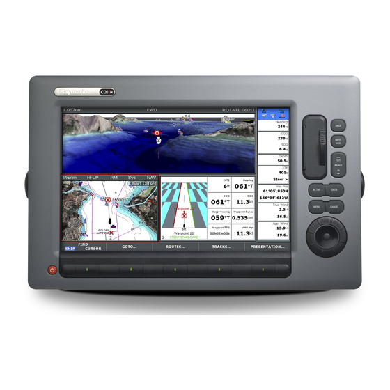
C-series widescreen multifunction display
Hide thumbs
Also See for C90W:
- User reference handbook (222 pages) ,
- Quick reference manual (10 pages)
Table of Contents
Advertisement
Advertisement
Table of Contents
Troubleshooting

Related Manuals for Raymarine C90W


Summary of Contents for Raymarine C90W
- Page 1 Multifunction Display Installation instructions C90W , C120W and C140W models...
- Page 3 Trademarks and registered trademarks Autohelm, HSB, RayTech Navigator, Sail Pilot, SeaTalk and Sportpilot are UK registered trademarks of Raymarine UK Limited. Pathfinder and Raymarine are UK registered trademarks of Raymarine Holdings Limited. 45STV, 60STV, AST, Autoadapt, Auto GST, AutoSeastate, AutoTrim, Bidata, G Series, HDFI, LifeTag, Marine Intelligence, Maxiview, On Board, Raychart, Raynav, Raypilot, RayTalk, Raystar, ST40, ST60+, Seaclutter, Smart Route, Tridata, UniControl and Waypoint Navigation are trademarks of Raymarine UK Limited.
-
Page 5: Table Of Contents
Contents Chapter 1 Important Information......7 3.3 Power connection ............. 23 3.4 SeaTalk network ............. 26 TFT LCD Displays ............8 3.5 NMEA 0183 connection ..........32 Water ingress ..............8 3.6 SeaTalk connection ........... 33 Disclaimers ..............8 3.7 Alarm connection ............34 CompactFlash cards ............ - Page 6 6.6 System data troubleshooting........64 6.7 SeaTalk LED indications.......... 65 6.8 Miscellaneous troubleshooting ........66 Chapter 7 Technical support ........69 7.1 Raymarine technical support........70 7.2 Sirius support............70 7.3 Navionics support ............. 71 Chapter 8 Technical specification......73 8.1 Technical specification..........74 Chapter 9 Options and accessories .......
-
Page 7: Chapter 1 Important Information
This equipment must be installed in accordance with unless instructed in this document. the Raymarine instructions provided. Failure to do so could result in poor product performance, personal injury, and/or damage to the vessel. -
Page 8: Tft Lcd Displays
IPX6, subjecting any Raymarine equipment to commercial click. high pressure washing equipment may cause water intrusion and subsequent equipment failure. Raymarine will not warrant Caution: Use the sun covers equipment subjected to high pressure washing. To protect your product against the damaging... -
Page 9: Compactflash Cards
(as applicable). Correct installation is required to ensure that EMC performance is Raymarine does not warrant that this product is error-free or that it not compromised. is compatible with products manufactured by any person or entity For optimum EMC performance we recommended that wherever other than Raymarine. -
Page 10: Suppression Ferrites
Whilst the WEEE Directive does not apply to some removed for any purpose (e.g. installation or maintenance), it must Raymarine products, we support its policy and ask you to be aware be replaced in the original position before the product is used. -
Page 11: Imo And Solas
Technical accuracy To the best of our knowledge, the information in this document was correct at the time it was produced. However, Raymarine cannot accept liability for any inaccuracies or omissions it may contain. In addition, our policy of continuous product improvement may change specifications without notice. - Page 12 C-Series Widescreen installation...
-
Page 13: Chapter 2 Planning The Installation
Chapter 2: Planning the installation Chapter contents • 2.1 Handbook information on page 14 • 2.2 Installation checklist on page 14 • 2.3 C-Series systems on page 15 • 2.4 Pack contents on page 17 • 2.5 Tools on page 19 Planning the installation... -
Page 14: Handbook Information
C-Series Widescreen range of multifunction displays. Installation Task The handbook is for use with the following models: Plan your system • C90W Widescreen Multifunction Display Obtain all required equipment and tools • C120W Widescreen Multifunction Display Site all equipment • C140W Widescreen Multifunction Display Route all cables. -
Page 15: C-Series Systems
2.3 C-Series systems The C-Series display can be used in a number of system types. Some examples are outlined here. Example system Radar C-Series display SeaTalk backbone Pilot Instrument CANCEL ENTER CANCEL ENTER MENU MENU SeaTalk SeaT alk SeaT alk Crossover Coupler DSM 300 Alarm... - Page 16 C-Series protocols SeaTalk utilizes a single backbone cable to which compatible instruments connect using a spur. Data and power are carried within Your C-Series Widescreen Multifunction Display can connect to the backbone. Devices that have a low draw can be powered from various instruments and displays to share information and so the network, although high current equipment will need to have a improve the functionality of the system.
-
Page 17: Pack Contents
2.4 Pack contents The NMEA 0183 standard carries similar information to SeaTalk. However it has the important difference that one cable will only carry information in one direction. For this reason NMEA 0183 is Unpack the display unit carefully to prevent damage. Save the generally used to connect a data receiver and a transmitter together, carton and packing in case the unit has to be returned for service. - Page 18 All models contain the following items: Description Bezel Gasket Suncover 1.5 m (4.9 ft) Power and data cable Screw pack Document pack, includes: • Multilingual CD Gasket • Installation instructions C-Series • Cutting template Widescreen display Micro fiber cleaning cloth Bezel Marine shield screen clean sample (North America only) Suncover...
-
Page 19: Tools
2.5 Tools Tools required for installation Power drill drill bit, Adhesive tape bracket mounting Screwdriver File 35 mm (1.3/8 in) 5 mm (3/16 in) drill bit, hole cutter , bracket mounting panel mounting D11580-1 Planning the installation... - Page 20 C-Series Widescreen installation...
-
Page 21: Chapter 3 Cables And Connections
Chapter 3: Cables and connections Chapter contents • 3.1 General cabling guidance on page 22 • 3.2 Connections overview on page 23 • 3.3 Power connection on page 23 • 3.4 SeaTalk network on page 26 • 3.5 NMEA 0183 connection on page 32 •... -
Page 22: General Cabling Guidance
• antennae. • Unless otherwise stated use only standard cables of the correct type, supplied by Raymarine. • Ensure that any non-Raymarine cables are of the correct quality Strain relief and gauge. For example, longer power cable runs may require larger wire gauges to minimize voltage drop along the run. -
Page 23: Connections Overview
D11210-1 3. SeaTalk Power distribution 4. SeaTalk Raymarine recommend that all power connections are made via a distribution panel. • All equipment must be powered from a breaker or switch, with appropriate circuit protection. • All equipment should where possible be wired to individual breakers. -
Page 24: Power Cable
Supply voltage (AWG) 0–5 m (0–16.4 ft) 12 V Grounding 24 V The following requirements apply when grounding Raymarine 5–10 m (16.4–32.8 ft) 12 V equipment: 24 V • Use a dedicated earthing plate (e.g. dynaplate) in contact with the water. - Page 25 Display Fuse • C90W 7 A in-line fuse fitted within power cable. • C120W • C140W Sharing a breaker Where more than 1 piece of equipment shares a breaker you must provide protection for the individual circuits. E.g. an in-line fuse for...
-
Page 26: Seatalk Hs Network
3.4 SeaTalk network The SeaTalk network allows you to network compatible displays and other digital devices. The C-Series Widescreen Display can use SeaTalk to connect to: • Another C-Series Widescreen Display. • A digital radar scanner. • A DSM300 or DSM30 sonar module. •... - Page 27 Radar connection You can connect up to 2 C-Series Widescreen displays together C-Series Widescreen displays are compatible with Raymarine digital using SeaTalk . Connect the displays directly or use a SeaTalk radar scanners. The scanner is connected using a SeaTalk cable.
- Page 28 Radar connected using SeaTalk switch Radar Radar HS switch C-Series display C-Series display SeaTalk Crossover Coupler 12/24V power D11372-1 12/24V power D11218-1 C-Series Widescreen installation...
- Page 29 Digital radar cables Cable Part number Notes You will need at least 2 cables to connect the digital radar scanner. 2.5 m (8.2 ft) extension A92141 One cable connects the scanner to a SeaTalk switch (or cross cable over coupler). The second cable then connects into the display. 5 m (16.4 ft) extension A55080 Note: The maximum cable length including all extensions is 25 m...
-
Page 30: Sonar Connection
Cable Part number Notes C-Series display SeaTalk switch E55058 8 way hub for network connection of multiple SeaTalk devices. E55060 SeaTalk coupler Couple for connection of a single SeaTalk device. Sonar connection The sonar connection is required for fishfinder applications. The C-Series display is connected to a sonar module (DSM) using a SeaTalk cable. - Page 31 Typical DSM system Cable Part number Notes 10 m (32.8 ft) SeaTalk E55051 DSM300 C Series Display Unit network cable 20 m (65.6 ft) SeaTalk E55052 network cable Fully waterproof SeaTalk network cables Connect directly from DSM to the rear of the display. Cable Part number Notes...
-
Page 32: Nmea 0183 Connection
3.5 NMEA 0183 connection The C-Series has 3 NMEA ports available: • Port 1: Input and output, 4800 / 9600 baud rate. Connections to NMEA 0183 devices are made using the supplied Power and data cable. • Port 2: Input and output, up to 38400 baud rate. •... -
Page 33: Seatalk Connection
3.6 SeaTalk connection SeaTalk cable For SeaTalk cables and extensions, use Raymarine SeaTalk cable Connections to SeaTalk equipment are made using the supplied accessories. multi-cable. Note: Power to SeaTalk instruments is not provided by the C-Series Widescreen Display. C-Series display... -
Page 34: Alarm Connection
3.7 Alarm connection Typical alarm connection An alarm buzzer can be connected using the power / data cable provided with the display. C-Series display 19 way multi-cable Power , data and video Grey Black -ve supply Black (from battery/ breaker) Black Alarm D11216-1... -
Page 35: Gps Connection
3.8 GPS connection High alarm loads and third party alarms You can use the alarm output to switch a relay. This may be useful Depending upon your GPS type it may be either connected via for connecting high loads such as third party alarm sounders or SeaTalk or NMEA 0183. -
Page 36: Ais Connection
3.10 Fastheading connection 3.9 AIS connection A compatible AIS can be connected using NMEA 0183. Fastheading data required for radar target acquisition (MARPA) may come from either the autopilot or a separate Raymarine Fastheading sensor. NMEA 0183 (4800) VHF an t enna e.g GPS data to VHF radio... -
Page 37: Seatalk Ng Connections
3.11 SeaTalk connections Typical SeaTalk system The C-Series Widescreen Display can connect as part of a ST70 ST70 Instrument Pilot Controller Transducer SeaTalk network. Wind The C-Series can use SeaTalk to communicate with: Transducer CANCEL ENTER CANCEL ENTER MENU MENU •... -
Page 38: Nmea 2000 Connection
12 V power supply. This may be appropriate provided from: manufacturers interface) • Raymarine equipment with a regulated 12 V supply. (e.g. a SmartPilot SPX course computer) • Other suitable 12 V supply. D11198-1 Note: SeaTalk does NOT supply power to multifunction displays and other equipment with a dedicated power supply input. -
Page 39: Video Connection
3.13 Video connection The C-Series has an input for connection of cameras or other types of video equipment. The video connection is made using the combined power and data cable supplied with the unit. The connection is compatible with NTSC and PAL equipment. Video connection C-Series display 19 way... - Page 40 C-Series Widescreen installation...
-
Page 41: Chapter 4 Location And Mounting
Chapter 4: Location and mounting Chapter contents • 4.1 Selecting a location on page 42 • 4.2 Flush mounting on page 45 • 4.3 Bracket (trunnion) mounting on page 46 • 4.4 Front bezel on page 48 Location and mounting... -
Page 42: Selecting A Location
4.1 Selecting a location – Minimum bend radius of 100 mm (3.94 in) unless otherwise stated. Warning: Potential ignition source – Use cable supports to prevent stress on connectors. This product is NOT approved for use in • Water ingress hazardous/flammable atmospheres. - Page 43 C-Series Widescreen dimensions appropriate waterproof rating.) • Below Decks mounting. C90W, C120W and C140W dimensions Provides good performance with GRP construction vessels, however GPS may be less effective in poor prevailing conditions. Note: Below decks mounting on vessels of non-GRP construction may require an external GPS mounted above decks.
- Page 44 Typical locations and GPS performance bulkhead, or the interior of larger vessels may result in a reduced GPS signal. • Other constructions. GPS performance may be adversely affected below decks. Seek professional assistance and consider use of an external GPS antenna mounted above decks. Prevailing conditions The weather and location of the boat can affect the GPS performance.
-
Page 45: Flush Mounting
4.2 Flush mounting The standard method for mounting a C-Series display is a flush or panel mounting arrangement. Before mounting the unit, ensure that you have: • Selected a suitable location • Identified the cable connections and route that the cables will take •... -
Page 46: Bracket (Trunnion) Mounting
4.3 Bracket (trunnion) mounting 5. Ensure that the unit fits into the removed area and then file around the cut edge until smooth. The C-Series widescreen display can be mounted on an optional 6. Drill four 4.5 mm (3/16 in) holes as indicated on the template bracket. - Page 47 Note: Bracket (trunnion) mounting kit is available as an optional accessory. 1. Mark the location of the mounting bracket screw holes on the chosen mounting surface. 2. Drill pilot holes for the screws using a suitable drill, taking care that there are no cables or anything that may be damaged behind the surface.
-
Page 48: Front Bezel
4.4 Front bezel Attaching the front bezel Before fitting the bezel you must have mounted the unit in its required location. 1. Carefully lift one edge of the screen protection film, so that it is accessible for removing when unit installation is complete. 2. - Page 49 5. Check that all control buttons are free to operate. It is suggested that you use your thumb or forefinger in a circular motion to do this. Removing the front bezel D11197-1 1. When removing the bezel, start at the bottom-middle and work around to the sides and top edge.
- Page 50 C-Series Widescreen installation...
-
Page 51: Chapter 5 System Checks
Chapter 5: System checks Chapter contents • 5.1 Initial power on test on page 52 • 5.2 GPS check on page 53 • 5.3 Radar check on page 54 • 5.4 Sonar check on page 56 • 5.5 Language selection on page 57 System checks... -
Page 52: Initial Power On Test
3. OK button. Use this to confirm a selection or entry. Powering the display on 1. Press and hold the POWER button until the Raymarine logo 2. Press OK. appears. 2. Press OK to acknowledge the warning window. -
Page 53: Gps Check
5.2 GPS check Note: A solid circle on the chart indicates that neither heading nor Course Over Ground (COG) data is available. Checking GPS operation You can check that the GPS is functioning correctly using the chart application. 1. Press the PAGE button to show the available pages in the toolbar. -
Page 54: Radar Check
5.3 Radar check Typical HD digital radar screen Warning: Radar scanner safety Before rotating the radar scanner, ensure all personnel are clear. Warning: Radar transmission safety The radar scanner transmits electromagnetic energy. Ensure all personnel are clear of the scanner when the radar is transmitting. - Page 55 Checking the bearing alignment rest facing forward (you should see the Raymarine logo wording 1. With your vessel under way: Align the bow with a stationary from the front of the vessel) when you place it in either standby object identified on the radar display An object between 1 &...
-
Page 56: Sonar Check
5.4 Sonar check 3. Press OK when the fishfinder is displayed. Warning: Sonar operation • NEVER operate the sounder with the boat out of the water. • NEVER touch the transducer face when the sounder is powered on. • SWITCH OFF the sounder if divers are likely to be within 25 ft (5 m) of the transducer. -
Page 57: Language Selection
5.5 Language selection The C-Series multifunction display can operate in the following languages: English (US) English (UK) Chinese Danish Dutch Finnish French German Greek Icelandic Italian Japanese Korean Norwegian Portuguese Russian Spanish Swedish 1. Press the MENU button to open the setup menu. 2. - Page 58 C-Series Widescreen installation...
-
Page 59: Chapter 6 Troubleshooting
Chapter 6: Troubleshooting Chapter contents • 6.1 Troubleshooting on page 60 • 6.2 Power up troubleshooting on page 60 • 6.3 Radar troubleshooting on page 61 • 6.4 GPS troubleshooting on page 62 • 6.5 Sonar troubleshooting on page 63 •... -
Page 60: Troubleshooting
Problem Possible causes Possible solutions All Raymarine products are, prior to packing and shipping, subjected to comprehensive test and quality assurance programs. However, The display does not Problem with power to Check relevant fuses if you experience problems with the operation of your C-Series start up. -
Page 61: Radar Troubleshooting
Check the status of the SeaTalk Switch. Check that SeaTalk cables are free from damage. Software mismatch Contact Raymarine between equipment may technical support. prevent communication. Switch at scanner Ensure scanner pedestal in OFF position. pedestal switch is in ON position. -
Page 62: Gps Troubleshooting
6.4 GPS troubleshooting Problem Possible causes Possible solutions The bearing of a target The radar bearing Check and adjust radar Problems with the GPS and their possible causes and solutions alignment requires on the radar screen is bearing alignment. are described here. incorrect. -
Page 63: Sonar Troubleshooting
Check that the DSM is problem. correctly connected to the display or SeaTalk switch. Check the status of the SeaTalk Switch. Check that SeaTalk cables are free from damage. Software mismatch Contact Raymarine between equipment may technical support. prevent communication. Troubleshooting... -
Page 64: System Data Troubleshooting
Check the power to the SeaTalk bus. Refer to the manufacturer’s handbook for the equipment in question. Software mismatch Contact Raymarine between equipment may technical support. prevent communication. C-Series Widescreen installation... -
Page 65: Seatalk Hs Led Indications
1 flashing green LED. indicates network connection Flashing damage. LED indicates network traffic) . Software mismatch Contact Raymarine No LEDs are illuminated. No power to the SeaTalk switch. between equipment may technical support prevent communication. -
Page 66: Miscellaneous Troubleshooting
Software mismatch Go to on system (upgrade www.raymarine.com required). and click on support for the latest software downloads. Corrupt data / other Perform a factory reset. - Page 67 Troubleshooting...
- Page 68 C-Series Widescreen installation...
-
Page 69: Chapter 7 Technical Support
Chapter 7: Technical support Chapter contents • 7.1 Raymarine technical support on page 70 • 7.2 Sirius support on page 70 • 7.3 Navionics support on page 71 Technical support... -
Page 70: Raymarine Technical Support
Sirius audio This contains Frequently Asked Questions, servicing information, www.sirius.com e-mail access to the Raymarine Technical Support Department and details of worldwide Raymarine agents. Telephone support In the USA call: +1 603 881 5200 extension 2444 In the UK, Europe, the Middle East, or Far East call:... -
Page 71: Navionics Support
7.3 Navionics support Navionics website www.navionics.com Technical support... - Page 72 C-Series Widescreen installation...
-
Page 73: Chapter 8 Technical Specification
Chapter 8: Technical specification Chapter contents • 8.1 Technical specification on page 74 Technical specification... -
Page 74: Technical Specification
In-line fuse (fitted within power cable) colors) • 7 A. (Standard 20 mm glass fuse) • C90W: 9 in display, 800 x 480 pixels • C120W: 12 in display, 1280 x 800 pixels • C140W: 14 in display, 1280 x 800 pixels Data connections. - Page 75 <=15 metre @ 95% of time (without SA), <=5metres @ 95% with WAAS/EGNOS • Geodetic Datum: WGS-84 (alternatives available through Raymarine display) • Update rate: Once a second • Helical antenna for even antenna gain across most display orientations • GPS data bridged to NMEA 0183, SeaTalk and SeaTalk outputs.
- Page 76 C-Series Widescreen installation...
-
Page 77: Chapter 9 Options And Accessories
Chapter 9: Options and accessories Chapter contents • 9.1 SeaTalk accessories on page 78 • 9.2 SeaTalk accessories on page 78 • 9.3 SeaTalk accessories on page 79 • 9.4 Spares and accessories on page 81 Options and accessories... -
Page 78: Seatalk Accessories
9.1 SeaTalk accessories 9.2 SeaTalk accessories SeaTalk cables and accessories for use with compatible products. SeaTalk cables and accessories for use with compatible products. Description Part No Notes Description Part No Notes NMEA / SeaTalk E85001 converter Backbone Kit A25062 Includes: D285 3 m (9.8 ft) SeaTalk... -
Page 79: Seatalk Hs Accessories
9.3 SeaTalk accessories Description Part No Notes Digital radar scanner cables SeaTalk 3 m (9.8 ft) A06035 backbone Scanner cables Connect the Radar scanner to either the SeaTalk switch or the cross over coupler. SeaTalk 5 m (16.4 ft) A06036 backbone Cable Part number... - Page 80 SeaTalk network cables SeaTalk hardware Cable Part number Notes SeaTalk network cables SeaTalk switch E55058 8 way hub for network Standard network cables connect compatible equipment to the SeaTalk switch (or connection of multiple cross over coupler), they have a waterproof connector at one end. SeaTalk devices.
-
Page 81: Spares And Accessories
Rotary Trackpad R62185 Seal Set (C90W) R62186 Description Part No Notes R62125 Seal Set (C120W) R62187 Flush mount kit (C90W) Seal Set (C140W) R62188 R62126 Flush mount kit (C120W) Keymat set R62189 Flush mount kit (C140W) R62127 Keycap set R62190... - Page 82 (C120W) Lower keyboard assy R62213 (C140W) Side keyboard assy R62214 Rotary keyboard assy R62215 Keyboard cable assy R62216 GPS assembly (C90W) R62217 R62218 GPS assembly (C120W) GPS assembly (C140W) R62218 R62219 GPS cable assy LVDS cable assy R62221 CCFL cable assy...
-
Page 83: Appendix A Connectors And Pinouts
Appendix A Connectors and pinouts Group- Signal Cable Color Power, data and video connector SCREEN not used NMEA1 7/0.15 Twisted Yello pair NMEA1 7/0.15 Brown NMEA1 7/0.15 Twisted White pair Item Remarks NMEA1 7/0.15 Green Identification PWR/NMEA/ST/Video NMEA2 7/0.15 Twisted Orange / Connector type 19 pin twist-lock... - Page 84 Screen BATT- Black CanH VIDEO RG179 75R coax CanL (or equiva- lent) SeaTalk (not connected) VIDEO Screen Note: Use only Raymarine cables when connecting to SeaTalk SeaTalk connector SeaTalk connector Item Remarks Item Remarks Identification STHS Identification ST2/NMEA2000 Connector type...
-
Page 85: Appendix B Nmea 0183 Sentences
Bearing and distance to waypoint Not connected rhumb line Not connected Depth below transducer Depth Note: Use only Raymarine cables when connecting to SeaTalk Water temperature Recommended minimum navigation information Radar system data Tracked target message Water speed and heading... - Page 86 Recommended minimum specific Geographic position loran c sentence GPS transit data Course over ground and ground speed Geographic position latitude longitude sentence Time and date GPS DOP and active satellites Wind speed and angle sentence Routes sentence GPS satellites in view sentence Waypoint location sentence Heading deviation and variation sentence...
- Page 87 Appendix C NMEA 2000 sentences Cross track error measured sentence Time and date sentence The C-Series Widescreen display supports the following NMEA 2000 sentences. These are applicable to NMEA 2000, SeaTalk Meteorological composite sentence and SeaTalk 2 protocols. GPS satellite fault detection data Transmit sentence 128267...
- Page 88 127245 Rudder 129539 NMEA 2000 GNSS DOPs message 127250 Vessel heading 129029 GNSS position data 126992 System time NMEA 2000 GNSS RAIM output 129545 message 129033 Time and date 129540 GNSS Sats in view 130310 Environmental parameters 127237 Heading / track control 130306 Wind data 129284...
- Page 89 127505 Fluid level 127498 Static engine parameters 126464 PGN List 126996 Product information NMEA 2000 sentences...
- Page 90 C-Series Widescreen installation...
- Page 92 Raymarine plc Raymarine Inc. Anchorage Park, Portsmouth, 21 Manchester Street, Merrimack, Hampshire PO3 5TD, New Hampshire 03054-4801, United Kingdom. USA. Tel: +44 (0) 23 9269 3611 Tel: +1 603.881.5200 Fax: +44 (0) 23 9269 4642 Fax: +1 603.864.4756 www.raymarine.com www.raymarine.com...
Need help?
Do you have a question about the C90W and is the answer not in the manual?
Questions and answers
how do i connect my C90W to a raymarine Pathfinder 4d 424 Scanner, I cant see that the data wire correlate