Table of Contents
Advertisement
Quick Links
Advertisement
Table of Contents

Related Manuals for AT&T DLC-100

Summary of Contents for AT&T DLC-100
- Page 1 Digital Life User Guide ATT-UM-V1.1-201303...
- Page 2 Product Number: ATT-UM-V1.1-201303 ©2012, 2013 AT&T Intellectual Proprieties. All rights reserved.
- Page 3 FCC Compliance Statement FCC Regulations The following FCC Regulations apply to most, if not all, 915MHz and 433MHz devices: This device complies with part 15 of the FCC Rules. Operation is subject to the following two conditions: (1) This device may not cause harmful interference, and (2) this device must accept any interference received, including interference that may cause undesired operation.
- Page 4 Safety Instructions RF Exposure Information This device meets the government’s requirements for exposure to radio waves. This device is designed and manufactured not to exceed the emission limits for exposure to radio frequency (RF) energy set by the Federal Communications Commission of the U.S. Government.
- Page 5 Safety Instructions Read these instructions. Keep these instructions. Heed all warnings. Follow all instructions. Do not use this apparatus near water. Clean only with dry cloth. Do not block any ventilation openings. Install in accordance with the manufacturer's instructions. Do not install near any heat sources such as radiators, heat registers, stoves, or other apparatus (including amplifiers) that produce heat.
- Page 6 Safety Instructions Ground the Product WARNING! Avoid electric shock and fire hazard! If this product connects to coaxial cable wiring, be sure the cable system is grounded (earthed). Grounding provides some protection against voltage surges and built-up static charges. Verify the Power Source from the On/Off Power Light When the on/off power light is not illuminated, the apparatus may still be connected to the power source.
- Page 7 Safety Instructions Protect the Product When Moving It Always disconnect the power source when moving the apparatus or connecting or disconnecting cables. Battery Replacement Warnings WARNING: The battery(ies) used in each device may present a fire or chemical burn hazard if mistreated. Do not recharge, disassemble, heat above 100°C (212°F) or dispose of in fire.
-
Page 8: Table Of Contents
Digital Life Controller Features and Operation ..................... 3 Digital Life Controller (DLC-100) Features ....................3 Digital Life Controller (DLC-100) Operation ....................4 Replacing the Digital Life Controller (DLC-100) Battery ................5 Keypad Features and Operation ........................6 Becoming Familiar with your Keypad (SW-ATT-PAD2W) Features ............6 Display .............................. - Page 9 Contents Sounding and Displaying Device Trouble Conditions ................21 Key Fob Features and Operation ........................ 23 Key Fob (SW-ATT-FOB) Operation ......................23 Replacing the Key Fob (SW-ATT-FOB) Batteries ..................24 Digital Life Customer Care Technical Support .................... 25 Creating/Changing Your Alarm Panel PIN ....................25 Creating/Changing Your Duress PIN .......................
- Page 10 Contents Recessed Door/Window Sensor Features and Operation ................36 Replacing the Recessed Door/Window Sensor (SW-ATT-RDW) Battery ..........36 Testing the Recessed Door/Window Sensor (SW-ATT-RDW) ..............37 Glass Break Sensor Features and Operation ....................38 Replacing the Glass Break Sensor (SW-ATT-GB) Batteries ..............38 Testing the Glass Break Detector (SW-ATT-GB) ..................
-
Page 11: Introduction To The Digital Life System
Digital Life – Life Style Services. About Your AT&T Digital Life System Your professionally installed AT&T Digital Life System (DLS) features a Digital Life Controller (DLC-100), which is typically installed in a closet, utility room or basement. Digital Life User Manual ATT-UM-V1.1-201303... -
Page 12: At&T Digital Life Central Monitoring Centers
Introduction to the Digital Life System The DLC-100 is a wireless controller that monitors a wide range of devices for the detection of fire (smoke detectors and CO detectors) and intrusion (door/window sensors, motion sensors and glass breakage sensors) alarms. Once the DLC-100 is installed and activated, it constantly monitors smoke detectors and CO detectors and automatically reports alarms to the AT&T Digital Life Central Monitoring Centers. -
Page 13: Digital Life Controller Features And Operation
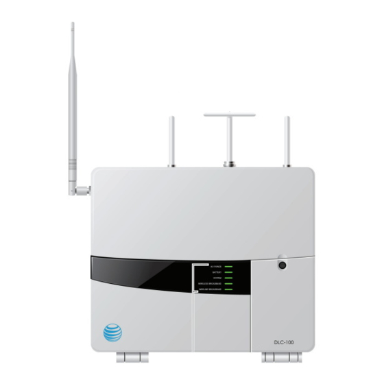
Your Digital Life System comes with a Digital Life Controller (DLC-100) that communicates with every device within your Digital Life System configuration. Your Digital Life Technician has installed your DLC-100 in a closet, utility room or basement. Digital Life Controller (DLC-100) Features 1. -
Page 14: Digital Life Controller (Dlc-100) Operation
Digital Life Controller Features and Operation Digital Life Controller (DLC-100) Operation The five (5) System LIGHTs on the DLC-100 door provide the following at-a-glance status: FEATURE OPERATION AC POWER • FLASHING GREEN LIGHT indicates your DLC is powering up •... -
Page 15: Replacing The Digital Life Controller (Dlc-100) Battery
If the SYSTEM LIGHT is flashing and then flashing and an auditory signal is coming from the Digital Life Controller Cabinet (DLC-100), the DLC- 100 is detecting Radio Frequency (RF) Jamming. Please call 1-855-288-2727 for Customer Care Technical Support. Replacing the Digital Life Controller (DLC-100) Battery CAUTION: Opening the battery compartment door when the system is armed triggers the transmission of a tamper alarm to the AT&T Digital Life Central Monitoring Center. -
Page 16: Keypad Features And Operation
Keypad Features and Operation Keypad Features and Operation Your Keypad (SW-ATT-PAD2W) enables you to control basic system functions, such as arming and disarming your Digital Life System. The keypad includes an LCD, which displays system status information, and features a built-in sounder that annunciates system status information. -
Page 17: System Lights
Keypad Features and Operation System LIGHTs If the Armed (Red) LIGHT is ON, a LCD message will indicate the status of the System: Armed-STAY or Armed-AWAY. If the Ready (Green) LIGHT is ON, the system is ready for arming. If the Armed (Red) LIGHT is OFF and the Ready (Green) LIGHT is OFF, then the system is not ready for arming because one or more of the monitored devices, such a door or window sensor, is not in the closed state Numeric Keypad... -
Page 18: Ready To Arm
Keypad Features and Operation Ready to Arm The system is ready to be armed when the READY (Green) LIGHT is on and no message is displayed on the LCD. Not Ready to Arm The system is not ready to arm because one, or more, of the supervised devices is not in the closed state. -
Page 19: Arming The System
Keypad Features and Operation Arming the System Before you can arm your system, all the devices must be closed. If some devices are currently open, the Ready light will be off. Before you try to arm your system, close all doors and windows, and make sure no one is present in areas with motion sensors. - Page 20 Keypad Features and Operation Arming the System-AWAY Press the AWAY button to arm all of the sensors, including perimeter and interior sensors. The system generates an exit delay timer interval. The keypad beeps and the LCD displays “Arming - Exit Now.” Initially the keypad beeps slowly during the exit delay timer interval and then chirps fast for the last ten (10) seconds.
- Page 21 Keypad Features and Operation Arming the System- BYPASS When arming the system for STAY or AWAY, you may get a message indicating that the system cannot arm because one, or more, sensor is in an opened state, such as a window and/or door. You may close the open sensor(s) before arming or utilize the BYPASS feature.
-
Page 22: Disarming The System - Entry Delay
Keypad Features and Operation The system will proceed with the Arming STAY/AWAY sequence. You should exit through the designated entry/exit door(s) before the exit delay timer interval expires. After the exit delay timer interval expires, the system is in the Armed-STAY or Armed-AWAY mode. The ARMED (Red) LIGHT is illuminated and the LCD displays “Armed - STAY”... -
Page 23: Disarming The System
Keypad Features and Operation After you enter your four (4) digit Alarm Panel PIN, the READY (Green) LIGHT is illuminated and the LCD is blank. Disarming the System When the system is in the Armed-STAY mode or Armed-AWAY mode, you enter your four (4) digit Alarm Panel PIN to disarm the system. -
Page 24: Alarm Sounding-Cancel Alarm
Keypad Features and Operation Alarm Sounding-Cancel Alarm If an alarm is triggered by opening a protected window or door while the system is armed, the siren will start sounding, the keypad starts beeping, and the LCD displays ”Alarm – Enter PIN to Cancel.” The keypad also displays the name of the device(s) that is/are triggered. -
Page 25: Sending A Fire Emergency Alarm
Keypad Features and Operation Sending a Fire Emergency Alarm In the case of a fire, press the FIRE button. You will be prompted to press the asterisk (*) key to confirm the Fire Emergency, as shown. After you press the asterisk (*) key, a fire alarm will be sent to the AT&T Digital Life Central Monitoring Center and the keypad will display “FIRE Emergency Sent,”... -
Page 26: Sending An Auxiliary Emergency Alarm
Keypad Features and Operation Sending an Auxiliary Emergency Alarm An AUX Emergency is any emergency other than Police, Fire or Medical, such as a flooded basement or a downed power line. In case of an Auxiliary Emergency, press the AUX button. You will be prompted to press the asterisk (*) key to confirm the AUX Emergency, as shown. -
Page 27: Sending A Police Emergency Alarm
Keypad Features and Operation Sending a Police Emergency Alarm In case of a police emergency, press the POLICE button. You will be prompted to press the asterisk (*) key to confirm the Police Emergency, as shown. After you press the asterisk (*) key, a Police Emergency alarm will automatically be sent to the AT&T Digital Life Central Monitoring Center and the keypad will display “POLICE Emergency Sent”... -
Page 28: Entering Your Duress Pin
Keypad Features and Operation Entering Your Duress PIN You can call a Digital Life Customer Care Technical Support agent to assist you in creating or changing your optional four (4) digit Duress PIN or you can access www.att.com/dlpin (See Digital Life Customer Care Technical Support). -
Page 29: Keypad And Siren Sounds
Keypad Features and Operation To replace the batteries: 1. Make sure that the system is disarmed before replacing the batteries. 2. Slide the keypad upward to remove the keypad from the base. 3. Turn the keypad to the backside. 4. Remove all existing batteries and dispose of them properly. ®... - Page 30 Keypad Features and Operation Feature Device(s) Sound Operation Siren (SW-ATT- CO Alarm Four (4) short one Four (4) beeps then silence (1) second beep repeats until Siren Timeout SRN) and Keypad sequence then Interval ends, which is (SW-ATT-PAD2W) silence repeating typically four (4) minutes Disarm Keypad...
-
Page 31: Priority Of Alarm Signaling
Sounder in DLC- Continuous tone During a condition of RF 100 Digital Life jamming the sounder in the Controller DLC-100 Digital Life Cabinet Controller Cabinet will beep continuously Chirp = 0.5 second Short Beep = 1 second Long Beep = 2 seconds Priority of Alarm Signaling There is an automatic prioritization of alarm signaling to the AT&T Digital Life Central... - Page 32 Keypad Features and Operation Trouble Condition Keypad Message Annunciation Silencing Missing Digital Life “Alarm Panel Battery Press # button on keypad Controller (DLC-100) Trouble” and “Press # to to silence chirping for four Battery Silence” (4) hours Low Digital Life Controller “Alarm Panel Battery...
-
Page 33: Key Fob Features And Operation
Your key fob has one LIGHT that flashes when a button is pressed and a signal is being transmitted to the DLC-100. It is battery operated and comes packaged with two (2) Panasonic CR2025 Lithium batteries that are preinstalled. -
Page 34: Replacing The Key Fob (Sw-Att-Fob) Batteries
Key Fob Features and Operation Use your Key Fob (SW-ATT-FOB) to perform one or more of these functions: KEY FOB FUNCTIONS Button/Function Action Fully arms the intrusion portion of the Digital Life Arm-AWAY Button System, including door/window sensors, glass break sensors and motion sensors. -
Page 35: Digital Life Customer Care Technical Support
Digital Life Customer Care Technical Support Digital Life Customer Care Technical Support Digital Life Customer Care Technical Support agents are available 24x7 to provide any assistance that you require, including: • Establish/change your mandatory four (4) digital Alarm Panel PIN •... -
Page 36: Changing The Exit Delay Timer
Siren Features and Operation Your wireless Siren (SW-ATT-SRN) is capable of generating alarms sounds and chirps. It is controlled by the DLC-100. It receives commands from the controller and generates tones and pre-programmed alarm sequences through its speaker. When a smoke alarm is activated the Siren (SW-ATT-SRN) will sound three short beeps then silence repeating. -
Page 37: Siren (Sw-Att-Srn) Operation
Siren Features and Operation Siren (SW-ATT-SRN) Operation The LIGHT shows the system status, as follows: • Solid Green—unit is AC powered and backup battery is good. • Blinking Green—unit is not AC powered and is operating on batteries. • Solid Red—unit is AC powered and the backup battery needs to be replaced. •... -
Page 38: Smoke Detector Features And Operation
(3) short beeps then silence repeating, whenever it detects smoke. It also transmits a smoke alarm to the DLC-100 and continues transmitting smoke detector signals every twenty (20) seconds as long as it is detecting smoke. -
Page 39: Testing Your Smoke Detector (Sw-Att-Smkt)
When the batteries are low, the internal transmitter will send a low battery report to the DLC-100, the smoke detector LIGHT is extinguished and the smoke detector will chirp every forty-five (45) seconds until the batteries are replaced. The low battery trouble chirps can be silenced for twenty-four (24) hours by pressing the TEST/SILENCE button. -
Page 40: Evacuation Plan
Evacuation Plan Evacuation Plan The purpose of an early warning smoke alarm is to detect the presence of fire in its early stages and sound an alarm giving the occupants time to exit the premises safely. NOTE: It is recommended that the Evacuation Plan be in accordance with ANSI/NFPA Avoiding Fire Hazards No detection device can protect life in all situations. -
Page 41: Always Be Prepared
Carbon Monoxide Detector Features and Operation Always be Prepared Practice the following steps to prepare you and your family in the event of a fire: • Perform fire drills regularly. Use them to assure recognition of an alarm signal. • Draw a floor plan and show two exits from each room. -
Page 42: Carbon Monoxide Detector (Sw-Att-Co) Operation
(4) short beeps then silence repeating. An alarm signal is transmitted to the DLC-100 within 15 seconds of detecting a dangerous concentration of carbon monoxide. NOTE: The alarm automatically resets when carbon monoxide is no longer detected. -
Page 43: Replacing The Carbon Monoxide Detector (Sw-Att-Co) Batteries
Carbon Monoxide Detector Features and Operation Operation LIGHT Alarm Status Display Sound Units Status Recommendation Trouble/ Red Alarm One quick Unit is in trouble Replace batteries. If service LIGHT beep every 30 condition. condition continues, unit flashes alarm seconds. has malfunctioned. every 30 Replace immediately. -
Page 44: Testing The Carbon Monoxide Detector (Sw-Att-Co)
Vanishing Door/Window Sensor Features and Operation Testing the Carbon Monoxide Detector (SW-ATT-CO) See the Test Your System section for instructions concerning testing your carbon monoxide detector(s). Maintaining the Carbon Monoxide Detector (SW-ATT-CO) To keep your alarm in good working order you should do the following: •... -
Page 45: Vanishing Door/Window Sensor Features And Operation
Your Vanishing Door/Window Sensor (SW-ATT-V2) is a fully monitored sensor that is designed to be installed on most doors or windows. The vanishing door/window sensor transmits intrusion alarm information to the DLC-100. Replacing the Vanishing Door/Window Sensor (SW-ATT-V2) Battery CAUTION: Opening the battery compartment door when the system is armed triggers the transmission of a tamper alarm to the AT&T Digital Life Central Monitoring Center. -
Page 46: Recessed Door/Window Sensor Features And Operation
Your Recessed Door/Window Sensor (SW-ATT-RDW) is a fully monitored sensor that transmits intrusion alarm information to the DLC-100. The detection portion of the device is imbedded into the door or window frame, while the magnet is installed adjacent to the detection device. -
Page 47: Testing The Recessed Door/Window Sensor (Sw-Att-Rdw)
Recessed Door/Window Sensor Features and Operation The recessed door/window sensor requires one (1) 3V CR2 Lithium Battery CR2 Lithium ® ® (Panasonic CR-2, GPI GPCR2). Reinsert the transmitter assembly into its housing. Replace the cap for the transmitter assembly. Insert the transmitter assembly into the door or window jam and install the screws for securing the transmitter (if they were used in the initial installation process). -
Page 48: Glass Break Sensor Features And Operation
Glass Break Sensor Features and Operation Your Glass Break Sensor (SW-ATT-GB) is a fully monitored sensor that transmits intrusion alarm information to the DLC-100. It is a tamper protected ceiling- or wall- mounted unit with a fifteen (15) foot maximum detection range, 360° maximum... -
Page 49: Testing The Glass Break Detector (Sw-Att-Gb)
Glass Break Sensor Features and Operation NOTE: If batteries are not installed, the sensor cannot be installed to its base. Testing the Glass Break Detector (SW-ATT-GB) See the Test Your System section concerning testing your Glass Break Detectors(s) (SW-ATT-GB). Digital Life User Manual ATT-UM-V1.1-201303 Page 39 of 62... -
Page 50: Motion Sensor Features And Operation
Motion Sensor Features and Operation Your Motion Sensor (PIR) (SW-ATT-PIR) is a fully monitored, tamper protected infrared motion detector that transmits intrusion alarm information to the DLC-100 Digital Life Controller. It is equipped with pet immunity. The motion sensor has field adjustable pet immunity settings for 33 and 55 pound animals, as well as, adjustable pulse count settings. -
Page 51: Testing The Pir Motion Sensor (Sw-Att-Pir)
Motion Sensor Features and Operation When you insert the new battery, ensure that careful attention is given to the polarity of the battery during battery installation. Reattach the motion sensor to its back plate. Testing the PIR Motion Sensor (SW-ATT-PIR) See the Test Your System section for instructions concerning end-to-end testing of your Motion Sensor(s) (SW-ATT-PIR). -
Page 52: 915Mhz Repeater Features And Operation
The 915MHz Repeater (SW-ATT-RPTR9) is used to “repeat” signals from 915MHz devices, such as Keypads (SW-ATT-PAD2W) or Sirens (SW-ATT-SRN), when they are too far away from the DLC-100 to be heard. Typically the 915MHz repeater is installed at the mid-point between the DLC-100 and the devices that are being repeated. -
Page 53: Replacing The 915Mhz Repeater (Sw-Att-Rptr9) Batteries
915MHz Repeater Features and Operation Replacing the 915MHz Repeater (SW-ATT-RPTR9) Batteries You can replace the batteries by opening the battery compartment located on the rear of the unit. You must first remove the retaining screw that is located at the top of the 915MHz Repeater (SW-ATT-RPTR9) that secures the 915 MHz repeater to the AC outlet and then remove the unit from the AC outlet. -
Page 54: 433Mhz Repeater Features And Operation
The 433MHz Repeater (SW-ATT-RPTR4) is used to “repeat” signals from devices, such as a smoke detector or a vanishing door/window sensor, when they are too far away from the DLC-100 to be heard. Typically the repeater is installed at the mid-point between the DLC-100 and the device(s) that is being repeated. - Page 55 433MHz Repeater Features and Operation NOTE: Be sure to observe the polarity of the batteries during battery replacement. After you have installed new batteries, plug the 433 MHz repeater back into the lower socket of the AC outlet. Then replace the retaining screw in the plastic tab at the top of the siren and secure the 433MHz repeater to the AC outlet.
-
Page 56: Takeover Module Features And Operation
In most installations, the Takeover Module (SW-ATT-TAKRF) will be installed adjacent to the DLC-100, but in some installations it may be installed in a different location in the home. All of the zones in the takeover module act as supervised wireless zones in the Digital Life System. -
Page 57: Replacing The Takeover Module (Sw-Att-Takrf) Batteries
Takeover Module Features and Operation Replacing the Takeover Module (SW-ATT-TAKRF) Batteries CAUTION: Opening the battery compartment door when the system is armed triggers the transmission of a tamper alarm to the AT&T Digital Life Central Monitoring Center. Therefore, in order to prevent a false alarm, please ensure that the system is disarmed prior to opening the battery compartment door to replace the batteries. -
Page 58: Cp-01-2010 Supported Features For False Alarm Reduction
CP-01-2010 Supported Features for False Alarm Reduction CP-01-2010 Supported Features for False Alarm Reduction The “Control Panel Standards – Features for False Alarm Reduction” standard was developed and adopted by a consensus of industry volunteers in accordance with the Security Industry Association (SIA) standards development policies and procedures. - Page 59 (Abort Delay). An Abort Delay will prevent a report to the AT&T Digital Life Central Monitoring Center if your DLC-100 is disarmed within thirty (30) to forty- five (45) seconds after an intrusion alarm is triggered. Note that fire-type alarms are normally reported without a delay.
- Page 60 AT&T Digital Life Central Monitoring Center. When the feature is enabled, the DLC-100 must receive two smoke detection messages from a smoke detector before reporting a smoke alarm to the AT&T Digital Life Central Monitoring Center.
- Page 61 CP-01-2010 Supported Features for False Alarm Reduction Digital Life CP-01 Feature Feature Default Name Name Settings Setting Feature Description speaking with a Digital Life Customer Care Technical Support agent or access www.att.com/dlpin. Disarm Disarm Basic You enter your four (4) digit Alarm system Panel PIN into a keypad to disarm operation...
-
Page 62: Testing Your System
Testing Your System Testing Your System Digital Life System Testing Instructions We recommend that you test your Digital Life System (DLS) on a weekly basis to ensure proper operation. If you determine that your DLS is not operating correctly, please call the Digital Life Central Monitoring Center at 1-855-288-2727 for Customer Care Technical Assistance. - Page 63 Testing Your System Device Procedure Results Notes • Keypad LCD will o Open one protected door or window Display: Alarm – Enter o After the alarm has PIN to Cancel • Keypad LCD will display: been observed, enter your Alarm Panel PIN Alarm Canceled •...
- Page 64 Testing Your System Device Procedure Results Notes activations of End-to-End Testing • Keypad LCD will display: motion detector, <PIR Device Name> - • Test each device one at which is done to Motion (For example, preserve battery a time by executing the “Great Room - Motion”) life following procedure:...
- Page 65 Testing Your System Device Procedure Results Notes CO Detector o After alarms have been observed, enter your Alarm Panel PIN to cancel the alarms and then enter your Alarm Panel PIN again to clear the message Smoke Detector (SW-ATT- SMK) •...
- Page 66 Testing Your System Device Procedure Results Notes observed, enter your unit replaced • Four (4) to Seven (7) Alarm Panel PIN to cancel the alarm and flashes: Unit is within then enter your Alarm normal sensitivity range. Panel PIN again to clear No action is required.
- Page 67 Testing Your System Device Procedure Results Notes Display: Alarm – Enter Functional Testing PIN to Cancel NOTE: You can only • Keypad LCD will display: execute this test if you Alarm Canceled have a glass break • Keypad LCD will display: simulator.
- Page 68 Testing Your System Device Procedure Results Notes Keypad (Auxiliary Emergency) (SW-ATT- PAD2W, SW- ATT-SRN) • DLS in Test Mode • Keypad LCD will display: • An Auxiliary • Press the AUXILIARY Press * to Confirm AUX Emergency alarm • Keypad LCD will display: button on the keypad has been sent to •...
- Page 69 Testing Your System Device Procedure Results Notes 433MHz Repeater (SW-ATT- RPTR4) • DLS in Test Mode End-to-End Testing • An Intrusion Alarm or Fire Alarm or • For each device Note: By testing outlying CO Alarm has 433MHz devices, • Keypad LCD will display: been sent to AT&T including Vanishing Digital Life Central...
- Page 70 Testing Your System Device Procedure Results Notes 915MHz Repeater (SW-ATT- RPTR9) • DLS in Test Mode Outlying Keypad • A Fire Emergency Testing has been sent to Note: By testing outlying AT&T Digital Life • Siren and outlying 915MHz devices, Central Monitoring including Keypads and keypad will sound a Fire...
- Page 71 Testing Your System Device Procedure Results Notes Panel PIN to cancel the alarms and then enter your Alarm Panel PIN again to clear the messages Outlying Siren Testing • Test each outlying siren one at a time by executing the following procedure: o Press the FIRE button on any...
- Page 72 Testing Your System Device Procedure Results Notes Takeover Module (SW-ATT- TAKRF) • DLS in End-to-End Testing • An Intrusion alarm • For each existing wired Test/Maintenance has been sent to Mode door/window sensor AT&T Digital Life • Keypad LCD will display: Central Monitoring Note: The Takeover Center with no...
Need help?
Do you have a question about the DLC-100 and is the answer not in the manual?
Questions and answers