Table of Contents
Advertisement
Quick Links
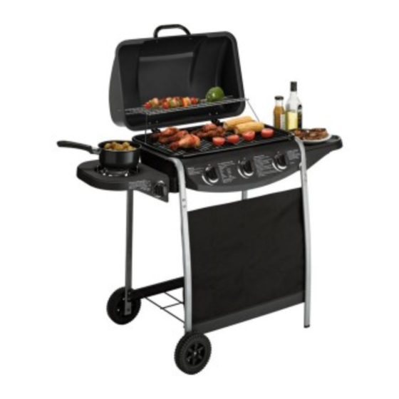
3 Burner Gas BBQ with side burner
Dimensions
Width - 125cm
Depth - 55.5cm
Height - 97cm
Important -
Please read this instructions fully before starting assembly
If you need help or have damaged or missing parts, call the Customer Helpline: 08456 400800.
Please keep for future reference
345/0925
Issue 1 - 7/9/11
Advertisement
Table of Contents

Related Manuals for Argos 345/0925


Summary of Contents for Argos 345/0925
- Page 1 3 Burner Gas BBQ with side burner Assembly Instructions - 345/0925 Please keep for future reference Dimensions Width - 125cm Depth - 55.5cm Height - 97cm Important - Please read this instructions fully before starting assembly If you need help or have damaged or missing parts, call the Customer Helpline: 08456 400800.
- Page 2 Safety and Care Advice Important - Please read this instructions fully before starting assembly Assembly time: approx. 45 mins. • Retain these instructions for future reference. • For outdoors use only – do not use indoors. Do not use below ground level and confined spaces. •...
- Page 3 Safety and Care Advice or tension. The hose should hang freely with no bends, folds, or kinks that could obstruct free flow of gas. Apart from the connection point, no part of the hose should touch any hot barbecue parts. Always inspect the hose for cuts, cracks, or excessive wear before use.
- Page 4 Safety and Care Advice Manual Ignition Instruction for Main Burner Insert lit match through the match-lighting hole at the side or bottom of the barbecue body. • Push in and turn the control knob anti-clockwise to the max position, the middle burner should ignite. •...
- Page 5 Safety and Care Advice Care and Maintenance Regularly clean your barbecue between uses and especially after extended periods of storage. Ensure the barbecue and its components are sufficiently cool before cleaning. Do not leave the barbecue exposed to outside weather conditions or stored in damp, moist areas. Never douse the barbecue with water when its surfaces are hot.
- Page 6 Safety and Care Advice Fixings All screws and bolts, etc. should be checked and tightened on a regular basis. Storage Store your barbecue in a cool dry place. It must be inspected on a regular basis as damp or condensation can form which may result in damage to the barbecue. It may be necessary to dry the barbecue and the inside of the cover if used.
- Page 7 If you have damaged or missing components, Components - Parts call the Customer Helpline: 08456 400800. Please check you have all the panels listed below Lid handle x1 Grill assembly x1 Cooking grill x1 Warming rack x1 Grease cup x1 Leg cap x2 Grease cup hanger x 1 Heat tent x3...
- Page 8 Components - Parts Please check you have all the panels listed below Wheel x 2 upper support x 2 Control panel assembly x 1 Side table x1 Front canvas x1 Bottom shelf x1 Side table front Side table rear Side burner assembly x1 support x1 support x1 Side burner...
- Page 9 Components - Fittings Please check you have all the panels listed below Note The quantities below are the correct amount to complete the assembly. : : : : 10mm Bolt x 8 M6 nut x 15 40mm Bolt x 8 25mm Bolt x 11 Axle x 2 10mm Bolt x 2...
-
Page 10: Assembly Instructions
Assembly Instructions Step 1 Put the right front leg right rear leg on the bottom shelf using 10mm bolts Fix the bolts tightly by the screwdriver. FRONT Step 2 Put the left front leg left rear leg on the bottom shelf using 10mm bolts Fix the bolts tightly by the... - Page 11 Assembly Instructions Step 3 Fix the leg caps to the right front leg and right rear leg Hammer the leg caps slightly to make it fix on the legs. FRONT Step 4 Insert the wheels to the left front leg and the left rear leg using the axles...
- Page 12 Assembly Instructions Step 5 Connect the upper support with the left front leg and left rear leg using 25mm bolts and M6 nuts Repeat the same connection of the upper support with the right front leg right rear leg using 25mm bolts and M6 nuts Fix the bolts tightly by the...
- Page 13 Assembly Instructions Step 7 Fix the burners of the grill assembly using 25mm bolts and M6 nuts Set the grill assembly on the upper supports and fix it by 40mm bolts and M6 nuts (Do not tighten the bolts at this stage.) Align all valves on the control panel assembly...
- Page 14 Assembly Instructions Step 8 Put the grease cup hanger through the hole of the the grill assembly Hang the grease cup the grease cup hanger Step 9 Place the heat tent top of each burner of the grill assembly Align the heat tent with tabs on its end against slots on the firebowl back.
- Page 15 Assembly Instructions Step 10 Put the washers between the lid handle and the lid of the grill assembly Align the holes and fix the lid handle on the lid of the grill assembly using 10mm bolts Fix the bolts tightly by the screwdriver.
- Page 16 Assembly Instructions Step 12 Install the side table assembly made in step 11 to the upper support 15mm shoulder bolts Step 13 Install the side burner assembly to the upper support using 15mm bolts...
- Page 17 Assembly Instructions Step 14 Fix the side burner valve on the side burner panel of the side burner assembly using 8mm bolts Put the side burner knob on the side burner assembly Put the side burner and the side burner electrode through the hole of side burner assembly...
- Page 18 Assembly Instructions Step 14 Align the venturi of the side burner against the valve. Important: Make sure the valve tip goes into the venturi tube completely with good alignment. Then tighten the side burner on the side burner assembly using 8mm bolt Burner venturi Connect the electrode of the main burner and the side...
- Page 19 Assembly Instructions Step 15 Put the cooking grill the warming rack on the grill assembly Step 16 Attach the front canvas to the left front leg right front leg Secure the position with the velcro on canvas edge.
- Page 20 Assembly Instructions Step 17 Assembly is complete. If you need help or have damaged or missing parts, call the Customer Helpline: 08456 400800.
- Page 21 Technical Specification Model Number KS10013 I3P (37) Gas Category Propane Type of Gas Gas Pressure 37 mbar 359/BU/1015 Pin Number 0.84mm Injector Size (Main Burner) Injector Size (Side Burner) 0.74mm 11.0 kW Total Heat Input 8.7 kW 3 Burner Heat Input Side Burner Heat Input 2.3 kW 785 g/h...
-
Page 22: Troubleshooting
Troubleshooting Problem Possible Cause Solution Burner will not light LP gas cylinder is empty Replace with full cylinder using the ignition Faulty regulator Have regulator checked or replace system Obstructions in burner Clean burner Obstructions in gas jets or gas hose Clean jets and gas hose Electrode wire is loose or disconnected Reconnect wire...
Need help?
Do you have a question about the 345/0925 and is the answer not in the manual?
Questions and answers