Lenze 8400 Hardware Manual
E84a series
Hide thumbs
Also See for 8400:
- Reference manual (1590 pages) ,
- Communications manual (94 pages) ,
- Mounting instructions (63 pages)

Related Manuals for Lenze 8400


Summary of Contents for Lenze 8400
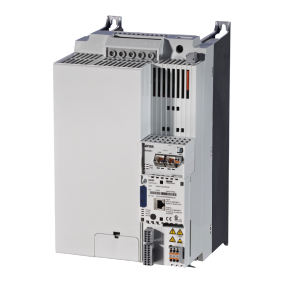
- Page 1 L-force Drives EDS84ASC552 .Q+ó Hardware Manual Translation 8400 0.25 ... 45 kW E84Axxxx StateLine C/HighLine C/TopLine C Frequency inverter 8400 ...
- Page 2 0Fig. 0Tab. 0...
-
Page 3: Table Of Contents
............General safety and application notes for Lenze controllers . - Page 4 Contents HighLine C control terminals ......... . . 4.7.1 External supply voltage 24 V .
- Page 5 Contents Installation according to EMC (installation of a CE-typical drive system) ..6.2.1 Shielding ........... . 6.2.2 Mains connection, DC supply .
- Page 6 ........8.2.5 Rating for Lenze brake resistors ....... . .
- Page 7 Contents 11.6 Memory module ........... . . 11.6.1 E84AYM10S .
-
Page 8: About This Documentation
About this documentation Document history About this documentation Contents The hardware manual provides the complete information on the application as directed of the 8400 controllers of the StateLine C, HighLine C, and TopLine C versions. Validity Type Type designation from hardware... -
Page 9: Conventions Used
About this documentation Conventions used Conventions used This documentation uses the following conventions to distinguish between different types of information: Spelling of numbers Decimal separator Point In general, the decimal point is used. For instance: 1234.56 Warnings UL warnings Given in English and French UR warnings ... -
Page 10: Terms And Abbreviations Used
About this documentation Terms and abbreviations used Terms and abbreviations used Term Meaning Device size Used as generic term for a group of devices which have the same dimensions (depth, height and width) but different power ratings. Standard device Used as generic term when actions and features are described which are very similar or the same for different versions or device sizes, e.g. -
Page 11: Notes Used
About this documentation Notes used Notes used The following pictographs and signal words are used in this documentation to indicate dangers and important information: Safety instructions Structure of safety instructions: Danger! (characterises the type and severity of danger) Note (describes the danger and gives information about how to prevent dangerous situations) Pictograph and signal word... -
Page 12: Safety Instructions
– The procedural notes and circuit details described in this documentation are only proposals. It is up to the user to check whether they can be transferred to the particular applications. Lenze Drives GmbH does not accept any liability for the suitability of the procedures and circuit proposals described. - Page 13 Safety instructions General safety and application notes for Lenze controllers Application as directed Controllers are components which are designed for installation in electrical systems or machines. They are not to be used as domestic appliances, but only for industrial purposes according to EN 61000-3-2.
- Page 14 Reduce housing openings and cutouts to a minimum. Lenze controllers may cause a DC current in the PE conductor. If a residual current device (RCD) is used for protection against direct or indirect contact for a controller with three-phase supply, only a residual current device (RCD) of type B is permissible on the supply side of the controller.
-
Page 15: General Safety And Application Instructions For Lenze Motors
Safety instructions General safety and application instructions for Lenze motors General safety and application instructions for Lenze motors (According to: Low-Voltage Directive 2006/95/EC) General Low-voltage machines have dangerous, live and rotating parts as well as possibly hot surfaces. Synchronous machines induce voltages at open terminals during operation. - Page 16 Safety instructions General safety and application instructions for Lenze motors Installation Ensure an even surface, solid foot/flange mounting and exact alignment if a direct clutch is connected. Avoid resonances with the rotational frequency and double mains frequency which may be caused by the assembly. Turn rotor by hand, listen for unusual slipping noises.
- Page 17 Safety instructions General safety and application instructions for Lenze motors Commissioning and operation Before commissioning after longer storage periods, measure insulation resistance. In case of values 1 k per volt of rated voltage, dry winding. For trial run without output elements, lock the featherkey. Do not deactivate the protective devices, not even in a trial run.
-
Page 18: Residual Hazards
Safety instructions Residual hazards Residual hazards Protection of persons Before working on the controller, check that no voltage is applied to the power ƒ terminals, because – depending on the controller - the power terminals U, V, W, +UG, -UG, Rb1 and Rb2 carry hazardous voltages for up to 3 to 20 minutes after mains disconnection. -
Page 19: Product Description
Product description Device features Product description Device features Version Features StateLine C HighLine C TopLine C Power range from 250 W to 45 kW Communication and diagnostic interfaces Integrated interference suppression acc. to EN 61800-3 ... -
Page 20: Overview Of Standard Devices
Product description Overview of standard devices Overview of standard devices Allocation of the device sizes Device size Power range [kW] GG 1 0.25 0.37 GG 2 0.55 0.75 GG 3 GG 4 GG 5 15.0 GG 6 18.5 22.0 GG 7 30.0 45.0 Standard device in device size GG 1 ... - Page 21 Product description Overview of standard devices Connection Information Pos. Description 230 V 400 V Terminal strip for the integrated safety unit 272 X100 Mains/DC-bus voltage (for 400 V devices) 184 194 – For devices in device size 6 (18.5 ... 22 kW) the terminal strip is not pluggable.
- Page 22 Product description Overview of standard devices Standard device in device size GG 7 8400GG100 Connection Information Pos. Description 230 V 400 V Terminal strip for the integrated safety unit 272 X100 Mains/DC-bus voltage (for 400 V devices) 204 –...
-
Page 23: Overview Of Control Terminals
Product description Overview of control terminals Overview of control terminals Control terminals for devices in the StateLine version Control terminals for devices in the HighLine version 8400HLC080a 8400HLC081a Connection Information Pos. Description StateLine C HighLine C CANopen connection 215 CANopen settings Analog inputs/outputs;... - Page 24 Product description Overview of control terminals Control terminals for devices in the TopLine version 8400TLC032b Connection Information Pos. Description TopLine C CANopen connection CANopen settings 215 Settings for CANopen terminating resistor and axis bus Analog inputs / outputs; 10 V reference voltage ...
-
Page 25: Identification
Product description Identification Identification The type data used in this manual refer to the nameplate which is placed at the front of the controller (Fig. 3-1). 8400SLC007 Fig. 3-1 Contents and position of the nameplate Device version Product key ... -
Page 26: Product Key
Product description Product key Product key Product range Inverter Drives 8400 Version A = 1. version Inverter type V = vector-controlled inverter Version SC = StateLine C HC = HighLine C TC = TopLine C Mounting type E = installation... -
Page 27: Technical Data
Technical data General data and operating conditions Technical data General data and operating conditions Conformity and approval Conformity 2006/95/EC Low-Voltage Directive About the safety of low voltage Eurasian conformity equipment (TR CU 004/2011) TR CU: Technical Regulations of Customs Electromagnetic compatibility of ... -
Page 28: Technical Data
Observe instructions regarding special measures. DC-bus operation Direct connection possible for devices with 400 V mains connection. Motors Only use motors suitable for inverter operation. Lenze L-force motors comply with the requirements. Environmental conditions Climate Storage IEC/EN 60721-3-1 1K3 (-25 ... +60 °C) - Page 29 Technical data General data and operating conditions Requirements on the motor cable Capacitance per unit length 2.5 mm /AWG 14 < 75/150 pF/m Core/core Core/shield 4 mm /AWG 12 < 150/300 pF/m Core/core Core/shield Electric strength VDE 0250-1 0.6/1.0 kV = r.m.s.
- Page 30 Technical data General data and operating conditions Motor cable lengths without considering EMC limit values Maximum length of the shielded motor cable [m] after switching frequencies rated rated [kW] 4 kHz 8 kHz 16 kHz 0.25 ... 2.2 0.37 ... 2.2 0.37 ...
- Page 31 Technical data General data and operating conditions Interference emission cable-guided EN 61800-3 Up to a shielded motor cable length of 25 m: Category C2 With interference suppression: Category C1 Radiation Category C2 Immunity to interference (acc. to EN 61800-3 requirements) Electrostatic discharge EN 61000-4-2 Air discharge: 8 kV,...
- Page 32 Technical data General data and operating conditions Open and closed loop control Open and closed loop control processes V/f characteristic control (VFCplus) Operation of asynchronous machines with a linear load torque characteristic Operation of asynchronous machines with a quadratic load torque characteristic ...
-
Page 33: Rated Data
Technical data Rated data Overview Rated data 4.2.1 Overview Input data Basis of the data Mains Voltage Voltage range Frequency range f [Hz] Lrated Lrated 1/N/PE AC 180 - 0 % ... 264 + 0 % 45 - 0 % ... 65 + 0 % 3/PE AC 320 - 0 % ... -
Page 34: Rated Data
Technical data Rated data Overview Output data Voltage Frequency Rated current [A] Number of phases [Hz] up to +45 °C up to +55 °C E84AVxxx2512 0 - 230 0 - 1000 E84AVxxx3712 0 - 230 0 - 1000 E84AVxxx5512 0 - 230 0 - 1000... - Page 35 Technical data Rated data Overview Power losses Power loss P Type when operating with rated output current I when controller is inhibited arated E84AVxxx2512 E84AVxxx3712 E84AVxxx5512 E84AVxxx7512 E84AVxxx1122 E84AVxxx1522 E84AVxxx2222 E84AVxxx3714 E84AVxxx5514 E84AVxxx7514 E84AVxxx1124 E84AVxxx1524 E84AVxxx2224 E84AVxxx3024xxS E84AVxxx3024xx0 E84AVxxx4024 E84AVxxx5524 E84AVxxx7524 E84AVxxx1134 E84AVxxx1534...
-
Page 36: Operation At Rated Mains Voltage 230 V
Technical data Rated data Operation at rated mains voltage 230 V 4.2.2 Operation at rated mains voltage 230 V Basis of the data Mains Voltage Voltage range Frequency range f [Hz] Lrated Lrated 1/N/PE AC 180 - 0 % ... 264 + 0 % 45 - 0 % ... - Page 37 Technical data Rated data Operation at rated mains voltage 230 V Switching frequency-dependent output currents Output currents [A] at switching frequency 2 kHz 4 kHz 8 kHz 16 kHz Type arated2 arated4 arated8 arated16 aM16 E84AVxxx2512 E84AVxxx3712 E84AVxxx5512 E84AVxxx7512 E84AVxxx1122 11.0 11.0 11.0...
- Page 38 Technical data Rated data Operation at rated mains voltage 230 V Fuses and cable cross-sections Operation without external mains choke/mains filter Type Installation according to EN 60204-1 Installation according to UL L1, N - laying system L1, N ...
- Page 39 Technical data Rated data Operation at rated mains voltage 230 V Operation with external mains choke/mains filter Installation according to EN 60204-1 Type Installation according to UL L1, N - laying system L1, N [AWG] [mA] E84AVxxx2512 ...
-
Page 40: Operation At Rated Mains Voltage 400 V
Technical data Rated data Operation at rated mains voltage 400 V 4.2.3 Operation at rated mains voltage 400 V Basis of the data Mains Voltage Voltage range Frequency range f [Hz] Lrated Lrated 3/PE AC 320 - 0 % ... 440 + 0 % 45 - 0 % ... - Page 41 Technical data Rated data Operation at rated mains voltage 400 V Assignment of external mains chokes Assignment Type Mains choke required Mains choke E84AVxxx3714 EZAELN3002B153 E84AVxxx5514 E84AVxxx7514 EZAELN3004B742 E84AVxxx1124 E84AVxxx1524 EZAELN3006B492 E84AVxxx2224 E84AVxxx3024xxS EZAELN3008B372 E84AVxxx3024xx0 EZAELN3008B372 E84AVxxx4024 EZAELN3010B292 E84AVxxx5524 EZAELN3016B182 E84AVxxx7524 EZAELN3020B152 E84AVxxx1134...
- Page 42 Technical data Rated data Operation at rated mains voltage 400 V Alternative DC supply Basis of the data Mains Voltage Voltage range Frequency range f [Hz] 2/PE DC 455 - 0 % ... 620 + 0 % Input current at I Output power Motor power U, V, W...
- Page 43 Technical data Rated data Operation at rated mains voltage 400 V Switching frequency-dependent output currents Output currents [A] at switching frequency 2 kHz 4 kHz 8 kHz 16 kHz Type arated2 arated4 arated8 arated16 aM16 E84AVxxx3714 E84AVxxx5514 E84AVxxx7514 E84AVxxx1124 E84AVxxx1524 E84AVxxx2224 11.2 11.2...
- Page 44 Technical data Rated data Operation at rated mains voltage 400 V Rated data for internal brake chopper Switching threshold V : 725 V, adjustable BRmax Bmin BRmax BRmax [] [kW] [kW] Type E84AVxxx3714 E84AVxxx5514 E84AVxxx7514 E84AVxxx1124 E84AVxxx1524 ...
- Page 45 Technical data Rated data Operation at rated mains voltage 400 V Fuses and cable cross-sections Operation without external mains choke/mains filter Type Installation according to EN 60204-1 Installation according to UL L1, L2, L3 - Laying system L1, L2, L3 ...
- Page 46 Technical data Rated data Operation at rated mains voltage 400 V Operation with external mains choke/mains filter Installation according to EN 60204-1 Type Installation according to UL L1, L2, L3 - Laying system L1, L2, L3 [AWG] [mA] E84AVxxx3714 E84AVxxx5514...
-
Page 47: Operation At A Rated Mains Voltage Of 500 V
Technical data Rated data Operation at a rated mains voltage of 500 V 4.2.4 Operation at a rated mains voltage of 500 V Basis of the data Mains Voltage Voltage range Frequency range f [Hz] Lrated Lrated 3/PE AC 400 - 0 % ... 550 + 0 % 45 - 0 % ... -
Page 48: Operation At A Rated Mains Voltage Of 500 V
Technical data Rated data Operation at a rated mains voltage of 500 V Assignment of external mains chokes Assignment Type Mains choke required Mains choke E84AVxxx3714 EZAELN3002B153 E84AVxxx5514 E84AVxxx7514 EZAELN3004B742 E84AVxxx1124 E84AVxxx1524 EZAELN3006B492 E84AVxxx2224 E84AVxxx3024xxS EZAELN3008B372 E84AVxxx3024xx0 EZAELN3008B372 E84AVxxx4024 EZAELN3010B292 E84AVxxx5524 EZAELN3016B182 E84AVxxx7524... - Page 49 Technical data Rated data Operation at a rated mains voltage of 500 V Alternative DC supply Basis of the data Mains Voltage Voltage range Frequency range f [Hz] 2/PE DC 565 - 0 % ... 775 + 0 % Input current at I Output power Motor power U, V, W...
- Page 50 Technical data Rated data Operation at a rated mains voltage of 500 V Switching frequency-dependent output currents Output currents [A] at switching frequency 2 kHz 4 kHz 8 kHz 16 kHz Type arated2 arated4 arated8 arated16 aM16 E84AVxxx3714 E84AVxxx5514 E84AVxxx7514 E84AVxxx1124 E84AVxxx1524 E84AVxxx2224...
- Page 51 Technical data Rated data Operation at a rated mains voltage of 500 V Rated data for internal brake chopper Switching threshold V : 790 V, adjustable BRmax Bmin BRmax BRmax [] [kW] [kW] Type E84AVxxx3714 E84AVxxx5514 E84AVxxx7514 ...
- Page 52 Technical data Rated data Operation at a rated mains voltage of 500 V Fuses and cable cross-sections Operation without external mains choke/mains filter Type Installation according to EN 60204-1 Installation according to UL L1, L2, L3 - Laying system L1, L2, L3 ...
- Page 53 Technical data Rated data Operation at a rated mains voltage of 500 V Operation with external mains choke/mains filter Installation according to EN 60204-1 Type Installation according to UL L1, L2, L3 - Laying system L1, L2, L3 ...
-
Page 54: Operation With Increased Power At A 230 V Mains
Technical data Rated data Operation with increased power at a 230 V mains 4.2.5 Operation with increased power at a 230 V mains With an increased continuous power, the inverter can be connected to a next higher and more powerful motor. The overload capacity according to operation with rated data continues to exist. - Page 55 Technical data Rated data Operation with increased power at a 230 V mains Assignment of external mains chokes Assignment Type Mains choke required Mains choke E84AVxxx2512 ELN1-0900H005 E84AVxxx3712 ELN1-0900H005 E84AVxxx5512 ELN1-0500H009 E84AVxxx7512 ELN1-0500H009 E84AVxxx1122 ELN1-0250H018 E84AVxxx1522 ELN1-0250H018 E84AVxxx2222 Switching frequency-dependent output currents Output currents [A] at switching frequency 2 kHz 4 kHz...
- Page 56 Technical data Rated data Operation with increased power at a 230 V mains Fuses and cable cross-sections Operation without external mains choke/mains filter Type Installation according to EN 60204-1 Installation according to UL L1, L2, L3 - Laying system L1, L2, L3 ...
-
Page 57: Operation With Increased Power At A 400 V Mains
Technical data Rated data Operation with increased power at a 400 V mains 4.2.6 Operation with increased power at a 400 V mains With an increased continuous power, the inverter can be connected to a next higher and more powerful motor. The overload capacity according to operation with rated data continues to exist. - Page 58 Technical data Rated data Operation with increased power at a 400 V mains Mains current at I Apparent output power Motor power with external without external mains choke mains choke U, V, W 4 pol. ASM Type [kVA] [kW] E84AVxxx3714 0.55 E84AVxxx5514 0.75...
- Page 59 Technical data Rated data Operation with increased power at a 400 V mains Switching frequency-dependent output currents Output currents [A] at switching frequency 2 kHz 4 kHz 8 kHz 16 kHz Type arated2 arated4 arated8 arated16 aM16 E84AVxxx3714 E84AVxxx5514 E84AVxxx7514 E84AVxxx1124 E84AVxxx1524 E84AVxxx2224...
- Page 60 Technical data Rated data Operation with increased power at a 400 V mains Fuses and cable cross-sections Operation without external mains choke/mains filter Type Installation according to EN 60204-1 Installation according to UL L1, L2, L3 - Laying system L1, L2, L3 ...
- Page 61 Technical data Rated data Operation with increased power at a 400 V mains Operation with external mains choke/mains filter Installation according to EN 60204-1 Type Installation according to UL L1, L2, L3 - Laying system L1, L2, L3 ...
-
Page 62: Operation With Increased Power At A 500 V Mains
Technical data Rated data Operation with increased power at a 500 V mains 4.2.7 Operation with increased power at a 500 V mains With an increased continuous power, the inverter can be connected to a next higher and more powerful motor. The overload capacity according to operation with rated data continues to exist. - Page 63 Technical data Rated data Operation with increased power at a 500 V mains Mains current at I Apparent output power Motor power with external without external mains choke mains choke U, V, W 4 pol. ASM Type [kVA] [kW] E84AVxxx3714 0.55 E84AVxxx5514 0.75...
- Page 64 Technical data Rated data Operation with increased power at a 500 V mains Switching frequency-dependent output currents Output currents [A] at switching frequency 2 kHz 4 kHz 8 kHz 16 kHz Type arated2 arated4 arated8 arated16 aM16 E84AVxxx3714 E84AVxxx5514 E84AVxxx7514 E84AVxxx1124 E84AVxxx1524 E84AVxxx2224...
- Page 65 Technical data Rated data Operation with increased power at a 500 V mains Fuses and cable cross-sections Operation without external mains choke/mains filter Type Installation according to EN 60204-1 Installation according to UL L1, L2, L3 - Laying system L1, L2, L3 ...
- Page 66 Technical data Rated data Operation with increased power at a 500 V mains Operation with external mains choke/mains filter Installation according to EN 60204-1 Type Installation according to UL L1, L2, L3 - Laying system L1, L2, L3 ...
-
Page 67: Current Characteristics
Technical data Current characteristics Current characteristics The controller limits its maximally possible motor current under the following operating conditions (”current derating”): If the maximum heatsink temperature is exceeded ƒ – In this case, the controller switches independently from switching frequency mode of 16 kHz to 8 kHz and from 8 kHz to 4 kHz (but not from 4 kHz to 2 kHz). - Page 68 Technical data Current characteristics The maximum output currents depending on the mains voltage and the switching frequency modes are shown in the following tables. Maximum output currents [A] at a fixed switching frequency and U = 230V 2 kHz 4 kHz 8 kHz 16 kHz Type...
- Page 69 Technical data Current characteristics Maximum output currents [A] at a fixed switching frequency and U = 400V 2 kHz 4 kHz 8 kHz 16 kHz Type aM02 aM04 aM08 aM016 aM16 E84AVxxx3714 E84AVxxx5514 E84AVxxx7514 E84AVxxx1124 E84AVxxx1524 E84AVxxx2224 11.2 11.2 11.2 E84AVxxx3024xxS 11.0 14.6...
- Page 70 Technical data Current characteristics Maximum output currents [A] at a variable switching frequency = 230V Type aM0v E84AVxxx2512 E84AVxxx3712 E84AVxxx5512 E84AVxxx7512 E84AVxxx1122 11.0 E84AVxxx1522 10.5 14.0 E84AVxxx2222 14.3 19.0 Maximum output currents [A] at a variable switching frequency = 400V/U = 500V Type aM0v...
-
Page 71: Overcurrent Operation
Technical data Overcurrent operation Overcurrent operation The controllers can be driven at higher amperages beyond the rated current if the duration of this overcurrent operation is time limited. Two utilisation cycles with a duration of 15 s and 180 s are defined. Within these utilisation cycles, an overcurrent is possible for a certain time if afterwards an accordingly long recovery phase takes place. - Page 72 = 4 kHz f = 8 kHz f = 16 kHz 180-s cycle amax Tip! For calculations of application-specific cycles please contact your Lenze contact person. EDS84ASC552 EN 10.0...
-
Page 73: Terminal Description
Technical data Terminal description Overview Terminal description 4.5.1 Overview Standard device in device size GG 1 ... 3 Standard device in device size GG 4 ... 6 8400HLC058 8400HLC057 Connection Pos. Description Number Mains/DC-bus voltage (for 400V devices) X100 – For devices in device size 6 (18.5 ... 22 kW) the terminal strip is not pluggable. - Page 74 Technical data Terminal description Overview Standard device in device size GG 7 8400GG101 Connection Pos. Description Number Mains/DC-bus voltage X100 – non-pluggable. X101 Relay output Motor/external brake resistor X105 – non-pluggable. X106 Motor temperature monitoring PE conductor (on the supply side/on the motor side) ...
- Page 75 Technical data Terminal description Overview Control terminals for devices in the StateLine version Control terminals for devices in the HighLine version 8400HLC080a 8400HLC081a Connection Number Pos. Description StateLine C HighLine C System bus (CANopen) System bus settings (CANopen) Analog inputs (voltage/current) Analog outputs (voltage/current) 10 V reference voltage Digital inputs...
- Page 76 Technical data Terminal description Overview Control terminals for devices in the TopLine version 8400TLC032a Connection Number Pos. Description TopLine C System bus (CANopen) System bus settings (CANopen) Analog inputs (voltage/current) Analog outputs (voltage/current) 10 V reference voltage Digital outputs 24 V voltage output Digital inputs Controller enable 24 V supply of the control electronics...
-
Page 77: Stateline C Control Terminals
Technical data StateLine C control terminals External supply voltage 24 V StateLine C control terminals 4.6.1 External supply voltage 24 V Labelling Feature Rated value X4/24E Connection for external 24 V supply 24 V in accordance with IEC 61131-2 voltage by a safely separated 19.2 ... -
Page 78: Analog Inputs
Technical data StateLine C control terminals Analog inputs 4.6.2 Analog inputs Labelling Feature Rated value X3/A1U Input ± 10 V Input resistance > 80 k Input voltage in case of open circuit Display ”0” (U < 0.2 V, absolute) Sampling frequency 1 kHz (1 ms) Accuracy ... -
Page 79: Digital Inputs
Rated value X101 In the Lenze setting, the relay switches if the controller changes to the ”Fault” device status. Observe the notes provided in the corresponding software manual if you would like to implement parameters other than envisaged in the Lenze setting. -
Page 80: Highline C Control Terminals
Technical data HighLine C control terminals External supply voltage 24 V HighLine C control terminals 4.7.1 External supply voltage 24 V Labelling Feature Rated value X5/24E Connection for external 24 V supply 24 V in accordance with IEC 61131-2 voltage by a safely separated 19.2 ... -
Page 81: Analog Inputs
Technical data HighLine C control terminals Analog inputs 4.7.2 Analog inputs Labelling Feature Rated value X3/A1U, A2U Input ± 10 V Input resistance > 80 k Input voltage in case of open circuit Display ”0” (U < 0.2 V, absolute) Sampling frequency 1 kHz (1 ms) Accuracy... -
Page 82: Digital Inputs
Rated value X101 In the Lenze setting, the relay switches if the controller changes to the ”Fault” device status. Observe the notes provided in the corresponding software manual if you would like to implement parameters other than envisaged in the Lenze setting. -
Page 83: Motor Holding Brake Connection
Technical data HighLine C control terminals Motor holding brake connection 4.7.7 Motor holding brake connection Labelling Feature Rated value X107/24B Connection for external 24 V supply voltage 24 V in accordance with IEC 61131-2 by a safely separated power supply unit X107/GB 19.2 ... -
Page 84: Topline C Control Terminals
ƒ I/O axis bus The state bus is a bus system exclusively designed for Lenze controllers via which up to 20 controllers can be connected and which serves to simulate a ”release cord” function. The state is controlled via the system module SFBDigitalOutput. -
Page 85: Multi-Encoder Connection
– Motors with an installed ENP and KTY - for these motors, correct temperature evaluation and motor protection are not possible with 8400. Labelling Feature Rated value Cable length (system cable is Max. - Page 86 (7 ... 12) Tab. 4-1 Rated voltage of the encoder The values provided in Tab. 4-1 apply if Lenze system cables are used at typical ambient temperatures. Different cables, cable cross-sections, or extreme ambient temperatures may require adaptation after another metrological measurement process.
-
Page 87: Resolver Connection
You can connect and operate: Resolvers ƒ – Parameterisation of the number of pole pairs in C00925 – Lenze setting: Number of pole pairs = 1. Multipole resolvers with a number of resolver pole pairs 2 ƒ Resolvers of other manufacturers ƒ... -
Page 88: Mechanical Installation
– Ensure unimpeded ventilation of cooling air and outlet of exhaust air. – You can install several controllers of the 8400 L-force Inverter Drives product range next to each other without any clearance in the control cabinet. The mounting plate of the control cabinet must be electrically conductive. -
Page 89: Standard Devices In A Power Range Of 0.25
Mechanical installation Standard devices in a power range of 0.25 ... 3 kW Assembly in built-in technique (standard) Standard devices in a power range of 0.25 ... 3 kW 5.2.1 Assembly in built-in technique (standard) You can choose between three variants for mounting the ”built-in unit” version of the controllers: Assembly without filter ƒ... - Page 90 Mechanical installation Standard devices in a power range of 0.25 ... 3 kW Assembly without filter in ”standard” technique Assembly without filter in ”standard” technique For mounting, use two screws M5 x >10 mm. The mounting location and material must ensure a durable mechanical connection.
- Page 91 Mechanical installation Standard devices in a power range of 0.25 ... 3 kW Assembly without filter in ”standard” technique StateLine, HighLine 8400GG105k Fig. 5-2 Dimensions for mounting [kW] [mm] [kg] E84AVxxE2512xXx 0.25 > 95 > 95 E84AVxxE3712xXx 0.37 E84AVxxE3714xXx 0.37 E84AVxxE551xxXx 0.55 >...
- Page 92 Mechanical installation Standard devices in a power range of 0.25 ... 3 kW Assembly without filter in ”standard” technique TopLine 8400GG105n Fig. 5-3 Device dimensions [kW] [mm] E84AVTCE2512xXx 0.25 E84AVTCE371xxXx 0.37 E84AVTCE551xxXx 0.55 E84AVTCE751xxXx 0.75 E84AVTCE112xxXx E84AVTCE152xxXx E84AVTCE222xxXx E84AVTCE3024xXS E84AVTCE2512xBx 0.25 E84AVTCE371xxBx 0.37...
- Page 93 Mechanical installation Standard devices in a power range of 0.25 ... 3 kW Assembly without filter in ”standard” technique TopLine 8400GG105k Fig. 5-4 Dimensions for mounting [kW] [mm] [kg] E84AVTCE2512xXx 0.25 E84AVTCE371xxXx 0.37 > 95 > 95 E84AVTCE551xxXx 0.55 E84AVTCE751xxXx 0.75 E84AVTCE112xxXx E84AVTCE152xxXx...
- Page 94 Mechanical installation Standard devices in a power range of 0.25 ... 3 kW Filter mounting in ”standard” technique Filter mounting in ”standard” technique For mounting, use two screws M5 x >10 mm. The mounting location and material must ensure a durable mechanical connection. Screw and washer assemblies or hexagon socket screws with washers are ƒ...
- Page 95 Mechanical installation Standard devices in a power range of 0.25 ... 3 kW Filter mounting in ”standard” technique E84ZESR007 Fig. 5-5 Assembly with footprint filter Proceed as follows for installation: 1. Prepare M5 threaded holes on the mounting plate and equip them with screws and washers.
- Page 96 Mechanical installation Standard devices in a power range of 0.25 ... 3 kW Filter mounting variant Filter mounting variant For mounting, use two screws M5 x >10 mm. The mounting location and material must ensure a durable mechanical connection. Screw and washer assemblies or hexagon socket screws with washers are ƒ...
- Page 97 Mechanical installation Standard devices in a power range of 0.25 ... 3 kW Filter mounting variant E84ZESR008 Fig. 5-6 Assembly with side-mounted filter Proceed as follows for installation: 1. Prepare M5 threaded holes on the mounting plate and equip them with screws and washers.
-
Page 98: Assembly In Push-Through Technique (Thermal Separation)
Installation steps How to proceed: 1. Prepare mounting cutout and mounting holes (threaded holes M5 recommended). 2. Insert the 8400 frequency inverter into the mounting cutout. 3. Tighten with 6 screw and washer assemblies M5 x 10 (cross screw connection recommended). -
Page 99: Assembly In Push-Through Technique (Thermal Separation)
Mechanical installation Standard devices in a power range of 0.25 ... 3 kW Assembly in push-through technique (thermal separation) StateLine, HighLine 8400GG105h Fig. 5-7 Device dimensions [kW] [mm] E84AVxxD2512xXx 0.25 E84AVxxD3712xXx 0.37 E84AVxxD3714xXx 0.37 E84AVxxD551xxXx 0.55 E84AVxxD751xxXx 0.75 E84AVxxD112xxXx E84AVxxD152xxXx E84AVxxD222xxXx E84AVxxD2512xBx 0.25... - Page 100 Mechanical installation Standard devices in a power range of 0.25 ... 3 kW Assembly in push-through technique (thermal separation) StateLine, HighLine 8400GG105g Fig. 5-8 Dimensions for mounting [kW] [mm] [kg] E84AVxxD2512xXx 0.25 > 95 > 95 E84AVxxD3712xXx 0.37 E84AVxxD3714xXx 0.37 E84AVxxD551xxXx 0.55 221 8.5 12.5 110 105...
- Page 101 Mechanical installation Standard devices in a power range of 0.25 ... 3 kW Assembly in push-through technique (thermal separation) TopLine 8400GG105i Fig. 5-9 Device dimensions [kW] [mm] E84AVTCD2512xXx 0.25 E84AVTCD371xxXx 0.37 E84AVTCD551xxXx 0.55 E84AVTCD751xxXx 0.75 E84AVTCD112xxXx E84AVTCD152xxXx E84AVTCD222xxXx E84AVTCD2512xBx 0.25 E84AVTCD371xxBx 0.37 E84AVTCD551xxBx...
- Page 102 Mechanical installation Standard devices in a power range of 0.25 ... 3 kW Assembly in push-through technique (thermal separation) TopLine 8400GG105g Fig. 5-10 Dimensions for mounting [kW] [mm] [kg] E84AVTCD2512xXx 0.25 E84AVTCD371xxXx 0.37 221 8.5 12.5 110 105 > 95 >...
-
Page 103: Mounting In "Cold Plate" Technique
Mechanical installation Standard devices in a power range of 0.25 ... 3 kW Mounting in ”cold plate” technique 5.2.3 Mounting in ”cold plate” technique The E84AVxxC... controllers are designed for assembly on coolers (e.g. collective coolers) in ”cold-plate” technique. Requirements for collective coolers A good thermal connection to the cooler is important for the trouble-free operation of the controller: The contact area between the collective cooler and the controller... -
Page 104: Mounting In "Cold Plate" Technique
Mechanical installation Standard devices in a power range of 0.25 ... 3 kW Mounting in ”cold plate” technique Ambient conditions The rated data and the derating factors at increased temperature also apply to the ƒ ambient temperature of the drive controllers. Temperature at the cooling plate of the drive controller: max. - Page 105 Mechanical installation Standard devices in a power range of 0.25 ... 3 kW Mounting in ”cold plate” technique StateLine, HighLine 8400GG105a Fig. 5-12 Dimensions for mounting [kW] [mm] [kg] E84AVxxC2512xX0 0.25 > 95 > 95 E84AVxxC3712xX0 0.37 E84AVxxC3714xX0 0.37 E84AVxxC551xxX0 0.55 12.5 >...
- Page 106 Mechanical installation Standard devices in a power range of 0.25 ... 3 kW Mounting in ”cold plate” technique TopLine 8400GG105d Fig. 5-13 Device dimensions [kW] [mm] E84AVTCC551xxX0 0.55 E84AVTCC751xxX0 0.75 E84AVTCC112xxX0 E84AVTCC152xxX0 E84AVTCC222xxX0 E84AVTCC551xxB0 0.55 E84AVTCC751xxB0 0.75 E84AVTCC112xxB0 E84AVTCC152xxB0 E84AVTCC222xxB0 ...
- Page 107 Mechanical installation Standard devices in a power range of 0.25 ... 3 kW Mounting in ”cold plate” technique TopLine 8400GG105a Fig. 5-14 Dimensions for mounting [kW] [mm] [kg] E84AVTCC551xxX0 0.55 12.5 > 95 > 95 E84AVTCC751xxX0 0.75 E84AVTCC112xxX0 E84AVTCC152xxX0 12.5 12.5 >...
- Page 108 Mechanical installation Standard devices in a power range of 0.25 ... 3 kW Mounting in ”cold plate” technique ”Slim” StateLine, HighLine 8400GG105e Fig. 5-15 Device dimensions [kW] [mm] E84AVxxC3714xXS 0.37 E84AVxxC551xxXS 0.55 E84AVxxC751xxXS 0.75 E84AVxxC112xxXS E84AVxxC152xxXS E84AVxxC222xxXS E84AVxxC3024xXS E84AVxxC3714xBS 0.37 E84AVxxC551xxBS 0.55 E84AVxxC751xxBS...
- Page 109 Mechanical installation Standard devices in a power range of 0.25 ... 3 kW Mounting in ”cold plate” technique ”Slim” StateLine, HighLine 8400GG105b Fig. 5-16 Dimensions for mounting [kW] [mm] [kg] E84AVxxC3714xXS 0.37 E84AVxxC551xxXS 0.55 > 95 > 95 E84AVxxC751xxXS 0.75 E84AVxxC112xxXS E84AVxxC152xxXS >...
- Page 110 Mechanical installation Standard devices in a power range of 0.25 ... 3 kW Mounting in ”cold plate” technique ”Slim” TopLine 8400GG105f Fig. 5-17 Device dimensions [kW] [mm] E84AVTCC2512xXS 0.25 E84AVTCC371xxXS 0.37 E84AVTCC551xxXS 0.55 E84AVTCC751xxXS 0.75 E84AVTCC112xxXS E84AVTCC152xxXS E84AVTCC222xxXS E84AVTCC3024xXS E84AVTCC2512xBS 0.25 E84AVTCC371xxBS 0.37...
- Page 111 Mechanical installation Standard devices in a power range of 0.25 ... 3 kW Mounting in ”cold plate” technique ”Slim” TopLine 8400GG105b Fig. 5-18 Dimensions for mounting [kW] [mm] [kg] E84AVTCC2512xXS 0.25 E84AVTCC371xxXS 0.37 > 95 > 95 E84AVTCC551xxXS 0.55 E84AVTCC751xxXS 0.75 E84AVTCC112xxXS E84AVTCC152xxXS...
-
Page 112: Standard Devices In The Power Range 3
Mechanical installation Standard devices in the power range 3 ... 22 kW Assembly in built-in technique (standard) Standard devices in the power range 3 ... 22 kW 5.3.1 Assembly in built-in technique (standard) You can choose between three variants for mounting the ”built-in unit” version of the controllers: Assembly without filter ƒ... - Page 113 Mechanical installation Standard devices in the power range 3 ... 22 kW Assembly without filter in ”standard” technique StateLine, HighLine 8400GG106h Fig. 5-19 Device dimensions [kW] [mm] E84AVxxE3024xXx E84AVxxE4024xXx E84AVxxE5524xXx E84AVxxE7524xXx E84AVxxE1134xXx E84AVxxE1534xXx E84AVxxE1834xXx 18.5 E84AVxxE2234xXx E84AVxxE3024xBx E84AVxxE4024xBx E84AVxxE5524xBx E84AVxxE7524xBx E84AVxxE1134xBx E84AVxxE1534xBx E84AVxxE1834xBx...
- Page 114 Mechanical installation Standard devices in the power range 3 ... 22 kW Assembly without filter in ”standard” technique StateLine, HighLine 8400GG106g Fig. 5-20 Dimensions for mounting [kW] [mm] [kg] E84AVxxE3024xXx E84AVxxE4024xXx > 95 > 95 E84AVxxE5524xXx E84AVxxE7524xXx E84AVxxE1134xXx > 95 >...
- Page 115 Mechanical installation Standard devices in the power range 3 ... 22 kW Assembly without filter in ”standard” technique TopLine 8400GG106i Fig. 5-21 Device dimensions [kW] [mm] E84AVTCE3024xXx E84AVTCE4024xXx E84AVTCE5524xXx E84AVTCE7524xXx E84AVTCE1134xXx E84AVTCE1534xXx E84AVTCE1834xXx 18.5 E84AVTCE2234xXx E84AVTCE3024xBx E84AVTCE4024xBx E84AVTCE5524xBx E84AVTCE7524xBx E84AVTCE1134xBx E84AVTCE1534xBx E84AVTCE1834xBx 18.5...
- Page 116 Mechanical installation Standard devices in the power range 3 ... 22 kW Assembly without filter in ”standard” technique TopLine 8400GG106g Fig. 5-22 Dimensions for mounting [kW] [mm] [kg] E84AVTCE3024xXx E84AVTCE4024xXx > 95 > 95 E84AVTCE5524xXx E84AVTCE7524xXx E84AVTCE1134xXx > 95 > 95 E84AVTCE1534xXx E84AVTCE1834xXx 18.5...
- Page 117 Mechanical installation Standard devices in the power range 3 ... 22 kW Filter mounting in ”standard” technique Filter mounting in ”standard” technique The mounting location and material must ensure a durable mechanical connection. Screw and washer assemblies or hexagon socket screws with washers are ƒ...
- Page 118 Mechanical installation Standard devices in the power range 3 ... 22 kW Filter mounting in ”standard” technique E84ZESR020 Fig. 5-23 Assembly with footprint filter Proceed as follows for installation: 1. Prepare M5 threaded holes on the mounting plate and equip them with screws and washers.
- Page 119 Mechanical installation Standard devices in the power range 3 ... 22 kW Filter mounting variant Filter mounting variant The mounting location and material must ensure a durable mechanical connection. Screw and washer assemblies or hexagon socket screws with washers are ƒ...
- Page 120 Mechanical installation Standard devices in the power range 3 ... 22 kW Filter mounting variant E84ZESR021 Fig. 5-24 Assembly with side-mounted filter Proceed as follows for installation: 1. Prepare M5 threaded holes on the mounting plate and equip them with screws and washers.
-
Page 121: Assembly In Push-Through Technique (Thermal Separation)
Installation steps How to proceed: 1. Prepare mounting cutout and mounting holes (threaded holes M5 recommended). 2. Insert the 8400 frequency inverter into the mounting cutout. 3. Tighten with 6 screw and washer assemblies M5 x 10 (cross screw connection recommended). -
Page 122: Assembly In Push-Through Technique (Thermal Separation)
Mechanical installation Standard devices in the power range 3 ... 22 kW Assembly in push-through technique (thermal separation) StateLine, HighLine 8400GG106d Fig. 5-26 Dimensions for mounting [kW] [mm] [kg] E84AVxxD3024xXx E84AVxxD4024xXx 150 150 15 0 > 95 > 95 4.9 1 1 E84AVxxD5524xXx... - Page 123 Mechanical installation Standard devices in the power range 3 ... 22 kW Assembly in push-through technique (thermal separation) TopLine 8400GG106f Fig. 5-27 Device dimensions [kW] [mm] E84AVTCD3024xXx E84AVTCD4024xXx E84AVTCD5524xXx E84AVTCD3024xBx E84AVTCD4024xBx E84AVTCD5524xBx EDS84ASC552 EN 10.0...
- Page 124 Mechanical installation Standard devices in the power range 3 ... 22 kW Assembly in push-through technique (thermal separation) TopLine 8400GG106d Fig. 5-28 Dimensions for mounting [kW] [mm] [kg] E84AVTCD3024xXx E84AVTCD4024xXx 150 150 15 0 > 95 > 95 5.1 1 1 E84AVTCD5524xXx E84AVTCD3024xBx...
- Page 125 Mechanical installation Standard devices in the power range 3 ... 22 kW Assembly in push-through technique (thermal separation) StateLine, HighLine 8400GG107e Fig. 5-29 Device dimensions [kW] [mm] E84AVxxD7524xXx E84AVxxD1134xXx E84AVxxD1534xXx E84AVxxD7524xBx E84AVxxD1134xBx E84AVxxD1534xBx EDS84ASC552 EN 10.0...
- Page 126 Mechanical installation Standard devices in the power range 3 ... 22 kW Assembly in push-through technique (thermal separation) StateLine, HighLine 8400GG107d Fig. 5-30 Dimensions for mounting [kW] [mm] [kg] E84AVxxD7524xXx E84AVxxD1134xXx 9 120 120 120 15 80 0 > 95 > 95 6.2 1 1 E84AVxxD1534xXx...
- Page 127 Mechanical installation Standard devices in the power range 3 ... 22 kW Assembly in push-through technique (thermal separation) TopLine 8400GG107f Fig. 5-31 Device dimensions [kW] [mm] E84AVTCD7524xXx E84AVTCD1134xXx E84AVTCD1534xXx E84AVTCD7524xBx E84AVTCD1134xBx E84AVTCD1534xBx EDS84ASC552 EN 10.0...
- Page 128 Mechanical installation Standard devices in the power range 3 ... 22 kW Assembly in push-through technique (thermal separation) TopLine 8400GG107d Fig. 5-32 Dimensions for mounting [kW] [mm] [kg] E84AVTCD7524xXx E84AVTCD1134xXx 9 120 120 120 15 80 0 > 95 > 95 6.4 1 1 E84AVTCD1534xXx...
-
Page 129: Mounting In "Cold Plate" Technique
Mechanical installation Standard devices in the power range 3 ... 22 kW Mounting in ”cold plate” technique 5.3.3 Mounting in ”cold plate” technique The E84AVxxC... controllers are designed for assembly on coolers (e.g. collective coolers) in ”cold-plate” technique. Requirements for collective coolers A good thermal connection to the cooler is important for the trouble-free operation of the controller: The contact area between the collective cooler and the controller... -
Page 130: Mounting In "Cold Plate" Technique
Mechanical installation Standard devices in the power range 3 ... 22 kW Mounting in ”cold plate” technique StateLine, HighLine 8400GG106b Fig. 5-33 Device dimensions [kW] [mm] E84AVxxC3024xX0 E84AVxxC4024xXx E84AVxxC5524xXx E84AVxxC3024xB0 E84AVxxC4024xBx E84AVxxC5524xBx EDS84ASC552 EN 10.0... - Page 131 Mechanical installation Standard devices in the power range 3 ... 22 kW Mounting in ”cold plate” technique StateLine, HighLine 8400GG106a Fig. 5-34 Dimensions for mounting [kW] [mm] [kg] E84AVxxC3024xX0 E84AVxxC4024xXx > 95 > 95 E84AVxxC5524xXx E84AVxxC3024xB0 E84AVxxC4024xBx > 95 > 95 E84AVxxC5524xBx ...
- Page 132 Mechanical installation Standard devices in the power range 3 ... 22 kW Mounting in ”cold plate” technique TopLine 8400GG106c Fig. 5-35 Device dimensions [kW] [mm] E84AVTCC3024xX0 E84AVTCC4024xXx E84AVTCC5524xXx E84AVTCC3024xB0 E84AVTCC4024xBx E84AVTCC5524xBx EDS84ASC552 EN 10.0...
- Page 133 Mechanical installation Standard devices in the power range 3 ... 22 kW Mounting in ”cold plate” technique TopLine 8400GG106a Fig. 5-36 Dimensions for mounting [kW] [mm] [kg] E84AVTCC3024xX0 E84AVTCC4024xXx > 95 > 95 E84AVTCC5524xXx E84AVTCC3024xB0 E84AVTCC4024xBx > 95 > 95 E84AVTCC5524xBx ...
- Page 134 Mechanical installation Standard devices in the power range 3 ... 22 kW Mounting in ”cold plate” technique StateLine, HighLine 8400GG107b Fig. 5-37 Device dimensions [kW] [mm] E84AVxxC7524xXx E84AVxxC1134xXx E84AVxxC1534xXx E84AVxxC1834xXx 18.5 E84AVxxC2234xXx E84AVxxC7524xBx E84AVxxC1134xBx E84AVxxC1534xBx E84AVxxC1834xBx 18.5 E84AVxxC2234xBx EDS84ASC552 EN 10.0...
- Page 135 Mechanical installation Standard devices in the power range 3 ... 22 kW Mounting in ”cold plate” technique StateLine, HighLine 8400GG107a Fig. 5-38 Dimensions for mounting [kW] [mm] [kg] E84AVxxC7524xXx E84AVxxC1134xXx 120 120 120 > 95 > 95 3.6 E84AVxxC1534xXx E84AVxxC1834xXx 18.5 8.5 130 130 130 5.5 110 110...
- Page 136 Mechanical installation Standard devices in the power range 3 ... 22 kW Mounting in ”cold plate” technique TopLine 8400GG107c Fig. 5-39 Device dimensions [kW] [mm] E84AVTCC7524xXx E84AVTCC1134xXx E84AVTCC1534xXx E84AVTCC1834xXx 18.5 E84AVTCC2234xXx E84AVTCC7524xBx E84AVTCC1134xBx E84AVTCC1534xBx E84AVTCC1834xBx 18.5 E84AVTCC2234xBx EDS84ASC552 EN 10.0...
- Page 137 Mechanical installation Standard devices in the power range 3 ... 22 kW Mounting in ”cold plate” technique TopLine 8400GG107a Fig. 5-40 Dimensions for mounting [kW] [mm] [kg] E84AVTCC7524xXx E84AVTCC1134xXx 120 120 120 > 95 > 95 3.8 E84AVTCC1534xXx E84AVTCC1834xXx 18.5 8.5 130 130 130 5.5 110 110 >...
-
Page 138: Standard Devices In A Power Range Of 30
Mechanical installation Standard devices in a power range of 30 ... 45 kW Assembly in built-in technique (standard) Standard devices in a power range of 30 ... 45 kW 5.4.1 Assembly in built-in technique (standard) You can choose between three variants for mounting the ”built-in unit” version of the controllers: Assembly without filter ƒ... - Page 139 Mechanical installation Standard devices in a power range of 30 ... 45 kW Assembly without filter in ”standard” technique Assembly without filter in ”standard” technique For mounting, use four screws M8 x >16 mm. The mounting location and material must ensure a durable mechanical connection.
- Page 140 Mechanical installation Standard devices in a power range of 30 ... 45 kW Assembly without filter in ”standard” technique StateLine, HighLine 8400GG108d Fig. 5-42 Dimensions for mounting [kW] [mm] [kg] E84AVxxE3034xXx E84AVxxE3734xXx > 95 > 120 17.2 E84AVxxE4534xXx E84AVxxE3034xBx E84AVxxE3734xBx >...
- Page 141 Mechanical installation Standard devices in a power range of 30 ... 45 kW Assembly without filter in ”standard” technique TopLine 8400GG108f Fig. 5-43 Device dimensions [kW] [mm] E84AVTCE3034xXx E84AVTCE3734xXx E84AVTCE4534xXx E84AVTCE3034xBx E84AVTCE3734xBx E84AVTCE4534xBx EDS84ASC552 EN 10.0...
- Page 142 Mechanical installation Standard devices in a power range of 30 ... 45 kW Assembly without filter in ”standard” technique TopLine 8400GG108d Fig. 5-44 Dimensions for mounting [kW] [mm] [kg] E84AVTCE3034xXx E84AVTCE3734xXx > 95 > 120 17.4 E84AVTCE4534xXx E84AVTCE3034xBx E84AVTCE3734xBx > 95 > 120 17.5 E84AVTCE4534xBx ...
- Page 143 Mechanical installation Standard devices in a power range of 30 ... 45 kW Filter mounting in ”standard” technique Filter mounting in ”standard” technique The mounting location and material must ensure a durable mechanical connection. Screw and washer assemblies or hexagon socket screws with washers are ƒ...
- Page 144 Mechanical installation Standard devices in a power range of 30 ... 45 kW Filter mounting in ”standard” technique E84AZESx003 Side-by-side filter Standard device [mm] [mm] [mm] [mm] [mm] [mm] E84AZESM3034LD E84AZESM3734LD E84AZESM4534LD E84AZESM4534LDN0 EDS84ASC552 EN 10.0...
- Page 145 Mechanical installation Standard devices in a power range of 30 ... 45 kW Filter mounting in ”standard” technique E84ZESx007 Proceed as follows for installation: 1. Prepare threaded holes on the mounting plate. 2. Equip threaded holes with screws and washers. –...
- Page 146 Mechanical installation Standard devices in a power range of 30 ... 45 kW Filter mounting variant Filter mounting variant The mounting location and material must ensure a durable mechanical connection. Screw and washer assemblies or hexagon socket screws with washers are ƒ...
- Page 147 Mechanical installation Standard devices in a power range of 30 ... 45 kW Filter mounting variant E84ZESx008 Proceed as follows for installation: 1. Prepare threaded holes on the mounting plate. 2. Equip threaded holes with screws and washers. – Use 8 screw and washer assemblies or hexagon socket screws with washers. –...
-
Page 148: Mounting In "Cold Plate" Technique
Mechanical installation Standard devices in a power range of 30 ... 45 kW Mounting in ”cold plate” technique 5.4.2 Mounting in ”cold plate” technique The E84AVxxC... controllers are designed for assembly on coolers (e.g. collective coolers) in ”cold-plate” technique. Requirements for collective coolers A good thermal connection to the cooler is important for the trouble-free operation of the controller: The contact area between the collective cooler and the controller... -
Page 149: Mounting In "Cold Plate" Technique
Mechanical installation Standard devices in a power range of 30 ... 45 kW Mounting in ”cold plate” technique StateLine, HighLine 8400GG108b Fig. 5-45 Device dimensions [kW] [mm] E84AVxxC3034xXx E84AVxxC3734xXx E84AVxxC4534xXx E84AVxxC3034xBx E84AVxxC3734xBx E84AVxxC4534xBx EDS84ASC552 EN 10.0... - Page 150 Mechanical installation Standard devices in a power range of 30 ... 45 kW Mounting in ”cold plate” technique StateLine, HighLine 8400GG108a Fig. 5-46 Dimensions for mounting [kW] [mm] [kg] E84AVxxC3034xXx E84AVxxC3734xXx > 95 > 120 16.7 E84AVxxC4534xXx E84AVxxC3034xBx E84AVxxC3734xBx > 95 > 120 16.8 E84AVxxC4534xBx ...
- Page 151 Mechanical installation Standard devices in a power range of 30 ... 45 kW Mounting in ”cold plate” technique TopLine 8400GG108c Fig. 5-47 Device dimensions [kW] [mm] E84AVTCC3034xXx E84AVTCC3734xXx E84AVTCC4534xXx E84AVTCC3034xBx E84AVTCC3734xBx E84AVTCC4534xBx EDS84ASC552 EN 10.0...
- Page 152 Mechanical installation Standard devices in a power range of 30 ... 45 kW Mounting in ”cold plate” technique TopLine 8400GG108a Fig. 5-48 Dimensions for mounting [kW] [mm] [kg] E84AVTCC3034xXx E84AVTCC3734xXx > 95 > 120 16.9 E84AVTCC4534xXx E84AVTCC3034xBx E84AVTCC3734xBx > 95 > 120 17.0 E84AVTCC4534xBx ...
-
Page 153: Electrical Installation
Electrical installation Important notes Electrical installation Important notes Danger! Hazardous electrical voltage Depending on the device, all power connections remain live up to 3 minutes after the mains has been switched off. Possible consequences: Death or severe injuries when touching the power terminals. ƒ... -
Page 154: Electrical Installation
Electrical installation Important notes Stop! No device protection if the mains voltage is too high The mains input is not internally fused. Possible consequences: Destruction of the device if the mains voltage is too high. ƒ Protective measures: Observe the maximally permissible mains voltage. ƒ... - Page 155 ƒ Monitoring of the IT system may be triggered. ƒ Protective measures: Do not use RFI filters from Lenze in IT systems. ƒ Before using the controller in IT systems, remove the two contact screws for ƒ interference suppression (on the supply side and on the motor side).
- Page 156 Electrical installation Important notes Danger! Operation of the controller on a phase earthed mains with a rated mains voltage of 400 V: The protection against accidental contact is not ensured without external ƒ measures. If protection against accidental contact acc. to EN 61800-5-1 is required for ƒ...
-
Page 157: Electrical Isolation
Electrical installation Important notes Electrical isolation 6.1.1 Electrical isolation The protective insulation of the ”8400 Inverter Drives” controllers is implemented according to EN 61800-5-1. The following illustration shows the insulation concept. E84AV E84AV E84AV X100 X100 X100 X100 X100 X100 Ext. -
Page 158: Device Protection
Electrical installation Important notes Device protection Range Connection Name Explanation Power X100 Mains DC bus Protective separation towards X101, X106 and all control terminals X105 Motor Brake resistor X101 Relay contact Protective separation towards X100, X105 and all control terminals X106 Motor temperature Protective separation towards X100, X105 and X101... -
Page 159: Maximum Motor Cable Length
Electrical installation Important notes Maximum motor cable length 6.1.3 Maximum motor cable length Ensure that the motor cable is as short as possible to have a positive effect on the ƒ drive behaviour. In group drives (multiple motors on one controller), the resulting cable length l ƒ... -
Page 160: Safety Instructions For The Installation According To Ul Or Ur
Electrical installation Safety instructions for the installation according to U or U 6.1.6 Safety instructions for the installation according to U or U Original - English Warnings! The integral solid state protection does not provide branch circuit protection ƒ and that branch circuit protection has to be provided externally in accordance with manufacturers instructions, the National Electrical Code and any additional codes. - Page 161 Electrical installation Safety instructions for the installation according to U or U Warnings! Control card protection: ƒ – 24 V DC class 2 supply or external fuse for 24 V DC supply voltage of control terminal X107. – Rated 4 A DC fuse UL248-14. –...
- Page 162 Electrical installation Safety instructions for the installation according to U or U The values of the fuses used may be equal to or fall below the values in the following table: Branch circuit protection Fuse [A] Circuit breaker [A] Type with mains choke without mains choke E84AVxxx2512...
- Page 163 Electrical installation Safety instructions for the installation according to U or U Warnings! For CSA Certification drives are intended to be used with Chokes - UL Recognized (XPTQ2/8, FOKY2/8) or CSA Certified (XPTQ2, FOKY2), File Number E103521 or E198787, mounted on the line side of the devices. The chokes are listed in chapter 4.2 Rated Data and chapter 11.2 Accessories.
-
Page 164: Safety Instructions For The Installation According To Ul Or Ur
Electrical installation Safety instructions for the installation according to U or U 6.1.7 Safety instructions for the installation according to U or U Original - French Avertissement ! La protection statique intégrée n’offre pas la même protection qu’un ƒ disjoncteur. - Page 165 Electrical installation Safety instructions for the installation according to U or U Avertissement ! Protection de la carte de commande : ƒ – Fusible externe pour tension d’alimentation 24 V CC du bornier de commande X107. – Fusible CC 4 A UL248-14 (tension assignée). –...
- Page 166 Electrical installation Safety instructions for the installation according to U or U Les valeurs des fusibles utilisés doivent être inférieures ou égales aux valeurs indiquées dans le tableau suivant : Branch circuit protection Fuse [A] Circuit breaker [A] Type with mains choke without mains choke E84AVxxx2512 E84AVxxx3712...
- Page 167 Electrical installation Safety instructions for the installation according to U or U Avertissement ! Pour obtenir la certification CSA, les entraînements doivent être destinés à une utilisation avec des selfs homologuées UL (XPTQ2/8, FOKY2/8) ou certifiées CSA (XPTQ2, FOKY2), n° de dossier E103521 ou E198787, montées côté alimentation des équipements.
-
Page 168: Installation According To Emc (Installation Of A Ce-Typical Drive System)
Electrical installation Installation according to EMC (installation of a CE-typical drive system) Shielding Installation according to EMC (installation of a CE-typical drive system) Design of the cables It is imperative to comply with the regulations concerning minimum cross-sections ƒ of PE conductors. The cross-section of the PE conductor must be at least as large as the cross-section of the power connections. - Page 169 Electrical installation Installation according to EMC (installation of a CE-typical drive system) Shielding Realisation 8400SLC024 Fig. 6-2 Wiring in compliance with EMC standards Mounting plate with electrically conductive surface Control cables, connect shielding to the upper shield sheet (PES) with a surface as large as ...
-
Page 170: Mains Connection, Dc Supply
Electrical installation Installation according to EMC (installation of a CE-typical drive system) Mains connection, DC supply 6.2.2 Mains connection, DC supply Controllers, mains chokes, or mains filters may only be connected to the mains via ƒ unshielded single cores or unshielded cables. When a mains filter or RFI filter is used, shield the cable between mains filter or RFI ƒ... -
Page 171: Motor Cable
ƒ install it separately from the motor cable. – In Lenze system cables, the cable for brake control is integrated into the motor cable. If this cable is not required for brake control, it can also be used to connect the motor temperature monitoring up to a length of 50 m. -
Page 172: Control Cables
Electrical installation Installation according to EMC (installation of a CE-typical drive system) Control cables 6.2.4 Control cables Control cables must be shielded to minimise interference injections. ƒ For lengths of approx. 5 m and more, use only shielded cables for analog and digital ƒ... -
Page 173: Installation In The Control Cabinet
Electrical installation Installation according to EMC (installation of a CE-typical drive system) Installation in the control cabinet 6.2.5 Installation in the control cabinet Mounting plate requirements Only use mounting plates with conductive surfaces (zinc-coated or V2A-steel). ƒ Painted mounting plates are not suitable even if the paint is removed from the ƒ... - Page 174 ƒ closely together over their entire length in order that no loops may occur. Mains fuses Mains contactors Fuses Line filter Line filter 24V power supply unit 8400 8400 Motor contactors Relays Wiring terminals 8400GGx008 Fig. 6-5 Cable routing in the control cabinet ...
-
Page 175: Wiring Outside Of The Control Cabinet
Electrical installation Installation according to EMC (installation of a CE-typical drive system) Wiring outside of the control cabinet 6.2.6 Wiring outside of the control cabinet Notes for cable routing outside the control cabinet: The longer the cables the greater the space between the cables must be. ƒ... - Page 176 Electrical installation Installation according to EMC (installation of a CE-typical drive system) Wiring outside of the control cabinet Wiring on the mains side It is possible to connect the controller, mains choke or RFI filter to the mains via ƒ single cores or unshielded cables.
-
Page 177: Detecting And Eliminating Emc Interferences
Electrical installation Installation according to EMC (installation of a CE-typical drive system) Detecting and eliminating EMC interferences 6.2.7 Detecting and eliminating EMC interferences Fault Cause Remedy Interferences of analog Unshielded motor cable Use shielded motor cable setpoints of your own or Shield contact is not extensive enough Carry out optimal shielding as specified other devices and... -
Page 178: Devices In The Power Range 0.25
Electrical installation Devices in the power range 0.25 ... 2.2 kW (1/N/PE AC 230 V) Example circuits Devices in the power range 0.25 ... 2.2 kW (1/N/PE AC 230 V) 6.3.1 Example circuits 1/N/PE AC 230 V X100 X101 COM NC NO +10 V/ E84AVSCxxxx ... - Page 179 Electrical installation Devices in the power range 0.25 ... 2.2 kW (1/N/PE AC 230 V) Example circuits X100 N L1 X101 1k .. 10k +10 V/ 10 mA 24 V 0 .. 10 V E84AV Cxxxx DC 24 V (+19.2 …+28.8 V) 0 ...10 V "...
- Page 180 Electrical installation Devices in the power range 0.25 ... 2.2 kW (1/N/PE AC 230 V) Example circuits N L1 X100 X101 1k .. 10k +10 V/ 10 mA 24 V 0 .. 10 V E84AVTCxxxx2 DC 24 V (+19.2 …+28.8 V) 0 ...10 V "...
- Page 181 Electrical installation Devices in the power range 0.25 ... 2.2 kW (1/N/PE AC 230 V) Example circuits Operation with rated power at the 230V mains, 3/PE Stop! Destruction of the device Devices with a 230V mains connection must not be connected to a three-phase 400V mains.
-
Page 182: Terminal Assignment Of The Power Connections
Electrical installation Devices in the power range 0.25 ... 2.2 kW (1/N/PE AC 230 V) Terminal assignment of the power connections 6.3.2 Terminal assignment of the power connections Preparing the cable installation To connect the shield of the motor cable, use the shield lug of the rear shield sheet. Position the shield sheet as follows: 1. -
Page 183: Terminal Assignment Of The Power Connections
Electrical installation Devices in the power range 0.25 ... 2.2 kW (1/N/PE AC 230 V) Terminal assignment of the power connections Strip cables X105 X106 84MOTL001_a 84MOTL001_b U, V, W T1, T2 [mm] [mm] [mm] E84AVxxx2512 E84AVxxx3712 E84AVxxx5512 E84AVxxx7512 E84AVxxx1122 E84AVxxx1522 E84AVxxx2222 How to proceed:... - Page 184 Electrical installation Devices in the power range 0.25 ... 2.2 kW (1/N/PE AC 230 V) Terminal assignment of the power connections Connecting the controller to protective earth Using the PE connection on the motor side the controller and the motor cable can be connected to protective earth.
- Page 185 Electrical installation Devices in the power range 0.25 ... 2.2 kW (1/N/PE AC 230 V) Terminal assignment of the power connections IT system Danger! The contact screws have to be removed when controllers are used in IT ƒ operation or when external filters of E84AZESRxxxxLL or E84AZESRxxxxSD type are used.
- Page 186 Electrical installation Devices in the power range 0.25 ... 2.2 kW (1/N/PE AC 230 V) Terminal assignment of the power connections Motor connection Terminal X105 Labelling Description U, V, W Motor PE conductor Functional earth " HF-shield termination by connection to PE 8400GGXx002b Terminal data Conductor...
- Page 187 Terminal assignment of the power connections Motor temperature monitoring Note! In the Lenze setting, motor temperature monitoring is activated! In the delivery status, there is a wire jumper between the terminals X106/T1 and X106/T2. Before connecting a thermal sensor, remove the wire jumper. ...
- Page 188 Electrical installation Devices in the power range 0.25 ... 2.2 kW (1/N/PE AC 230 V) Terminal assignment of the power connections Connection of external brake resistor Terminal X105 Labelling Description Rb1, Rb2 Brake resistor Functional earth HF-shield termination by connection to PE "...
-
Page 189: Devices In The Power Range 0.37
Electrical installation Devices in the power range 0.37 ... 22 kW (3/PE AC 400 V) Example circuits Devices in the power range 0.37 ... 22 kW (3/PE AC 400 V) 6.4.1 Example circuits 3/PE AC 400 V/500 V F1 … F3 L2 L3 X101 COM NC NO... - Page 190 Electrical installation Devices in the power range 0.37 ... 22 kW (3/PE AC 400 V) Example circuits F1 … F3 L2 L3 X101 X100 1k .. 10k +10 V/ 10 mA 24 V E84AV Cxxxx 0 .. 10 V DC 24 V (+19.2 …+28.8 V) 0 ...10 V "...
- Page 191 Electrical installation Devices in the power range 0.37 ... 22 kW (3/PE AC 400 V) Example circuits F1 … F3 L2 L3 X101 X100 1k .. 10k +10 V/ 10 mA 24 V 0 .. 10 V E84AVTCxxxx4 DC 24 V (+19.2 …+28.8 V) 0 ...10 V "...
-
Page 192: Terminal Assignment Of The Power Connections
Electrical installation Devices in the power range 0.37 ... 22 kW (3/PE AC 400 V) Terminal assignment of the power connections 6.4.2 Terminal assignment of the power connections Preparing the cable installation To connect the shield of the motor cable, use the shield lug of the rear shield sheet. Position the shield sheet as follows: 1. -
Page 193: Terminal Assignment Of The Power Connections
Electrical installation Devices in the power range 0.37 ... 22 kW (3/PE AC 400 V) Terminal assignment of the power connections Strip cables X105 X106 84MOTL001_a 84MOTL001_b U, V, W T1, T2 [mm] [mm] [mm] E84AVxxx3714 E84AVxxx5514 E84AVxxx7514 E84AVxxx1124 E84AVxxx1524 E84AVxxx2224 E84AVxxx3024xxS E84AVxxx3024xx0... - Page 194 Electrical installation Devices in the power range 0.37 ... 22 kW (3/PE AC 400 V) Terminal assignment of the power connections Connecting the controller to protective earth Using the PE connection on the motor side the controller and the motor cable can be connected to protective earth.
- Page 195 Electrical installation Devices in the power range 0.37 ... 22 kW (3/PE AC 400 V) Terminal assignment of the power connections IT system Danger! The contact screws have to be removed when controllers are used in IT ƒ operation or when external filters of E84AZESRxxxxLL or E84AZESRxxxxSD type are used.
- Page 196 Electrical installation Devices in the power range 0.37 ... 22 kW (3/PE AC 400 V) Terminal assignment of the power connections X100 - IT X105 - IT E8400GG006 E8400GG014 Fig. 6-20 Removal of the contact screws for device sizes 1 ... 3 (on the supply side and on the motor side) X100 - IT X105 - IT 8400GG055...
- Page 197 Electrical installation Devices in the power range 0.37 ... 22 kW (3/PE AC 400 V) Terminal assignment of the power connections Connection to the DC bus (+U , -U Terminal X100 Labelling Description Alternative connection of the DC-bus voltage Connection for the PE conductor 8400GGx001b Terminal data Conductor...
- Page 198 Electrical installation Devices in the power range 0.37 ... 22 kW (3/PE AC 400 V) Terminal assignment of the power connections Motor connection Terminal X105 Labelling Description U, V, W Motor PE conductor Functional earth " HF-shield termination by connection to PE 8400GGXx002b Terminal data Conductor...
- Page 199 Terminal assignment of the power connections Motor temperature monitoring Note! In the Lenze setting, motor temperature monitoring is activated! In the delivery status, there is a wire jumper between the terminals X106/T1 and X106/T2. Before connecting a thermal sensor, remove the wire jumper. ...
- Page 200 Electrical installation Devices in the power range 0.37 ... 22 kW (3/PE AC 400 V) Terminal assignment of the power connections Connection of external brake resistor Terminal X105 Labelling Description Rb1, Rb2 Brake resistor Functional earth HF-shield termination by connection to PE "...
-
Page 201: Devices In A Power Range Of 30
Electrical installation Devices in a power range of 30 ... 45 kW (3/PE AC 400 V) Example circuits Devices in a power range of 30 ... 45 kW (3/PE AC 400 V) 6.5.1 Example circuits Use the example circuits provided in the previous chapter ( 189). ... -
Page 202: Terminal Assignment Of The Power Connections
Electrical installation Devices in a power range of 30 ... 45 kW (3/PE AC 400 V) Terminal assignment of the power connections 6.5.2 Terminal assignment of the power connections Preparing the cable installation To connect the shield of the motor cable, use the shield lug of the rear shield sheet. Position the shield sheet as follows: 1. -
Page 203: Terminal Assignment Of The Power Connections
Electrical installation Devices in a power range of 30 ... 45 kW (3/PE AC 400 V) Terminal assignment of the power connections Strip cables X105 X106 84MOTL001_a 84MOTL001_b U, V, W T1, T2 [mm] [Nm] [mm] [Nm] [mm] [AWG] [lb-in] [AWG] [lb-in] [AWG]... - Page 204 Electrical installation Devices in a power range of 30 ... 45 kW (3/PE AC 400 V) Terminal assignment of the power connections Connecting the controller to protective earth Using the PE connection on the motor side the controller and the motor cable can be connected to protective earth.
- Page 205 Electrical installation Devices in a power range of 30 ... 45 kW (3/PE AC 400 V) Terminal assignment of the power connections IT system Danger! The contact screws have to be removed when controllers are used in IT ƒ operation or when external filters of E84AZESRxxxxLL or E84AZESRxxxxSD type are used.
- Page 206 Electrical installation Devices in a power range of 30 ... 45 kW (3/PE AC 400 V) Terminal assignment of the power connections X100 - IT X105 - IT 8400GG090b 8400GG094b Fig. 6-24 Removal of the contact screws for device size GG7 (on the supply side and on the motor side) ...
- Page 207 Electrical installation Devices in a power range of 30 ... 45 kW (3/PE AC 400 V) Terminal assignment of the power connections Connection to the DC bus (+U , -U Terminal X100 Labelling Description Alternative connection of the DC-bus voltage Connection for the PE conductor 8400GG096b Terminal data...
- Page 208 Electrical installation Devices in a power range of 30 ... 45 kW (3/PE AC 400 V) Terminal assignment of the power connections Motor connection Terminal X105 Labelling Description U, V, W Motor PE conductor Functional earth HF-shield termination by connection to PE 8400GG097a Terminal data Conductor...
- Page 209 Terminal assignment of the power connections Motor temperature monitoring Note! In the Lenze setting, motor temperature monitoring is activated! In the delivery status, there is a wire jumper between the terminals X106/T1 and X106/T2. Before connecting a thermal sensor, remove the wire jumper. ...
- Page 210 Electrical installation Devices in a power range of 30 ... 45 kW (3/PE AC 400 V) Terminal assignment of the power connections Connection of external brake resistor Terminal X105 Labelling Description Rb1, Rb2 Brake resistor Functional earth HF-shield termination by connection to PE 8400GG097b Terminal data Conductor...
-
Page 211: Common Control Terminals
Electrical installation Common control terminals Important notes Common control terminals 6.6.1 Important notes Stop! The device contains components that can be destroyed by electrostatic discharge! Before working on the device, the personnel must ensure that they are free of electrostatic charge by using appropriate measures. - Page 212 Electrical installation Common control terminals Important notes Preparing the cable installation The shields of the control cables are connected to the left shield lug of the front shield sheet. For this, proceed as shown in the illustration. 1. Release the holding screw of the shield sheet. 2.
- Page 213 Electrical installation Common control terminals Important notes Strip cables According to the selected lock-in position of the shield sheet, strip the control cables. For this, strip the cable ends and the cable sheath at the shield lug. The following table shows the stripping length for the control cables depending on the selected lock-in position of the shield sheet.
- Page 214 Electrical installation Common control terminals Important notes Shield and connect cables The uncovered cable shield at the left shield lug of the stripped control cables must be connected using a (metal) cable tie for high conductivity. As shown in the illustration, the cable ends (if required, provided with wire end ferrule) must be inserted into the corresponding spring terminals with a suitable screwdriver (for max.
-
Page 215: System Bus Connection (Canopen)
Basic structure of the CAN network Every segment of the CAN network must be terminated by resistors (120 )) between CAN Low and CAN High. The 8400 controller has one integrated bus terminating resistor each which can be activated via DIP switch. - Page 216 Electrical installation Common control terminals System bus connection (CANopen) 6.6.2.1 Wire CAN plug connector (X1) and ensure bus termination. Wire CAN plug connector (X1). ƒ – Only install shielded bus cables to avoid interference injection. – Fix the bus cable connected to plug connector X1 to the shield sheet of the controller.
- Page 217 Electrical installation Common control terminals System bus connection (CANopen) TopLine c b a 64 32 16 8 4 2 1 Baud CAN Adress EDS84AVxxxx 120Ω CAN-High CAN-Low CAN-Ground " " " 8400TLC002a 8400TLC008 Fig. 6-30 CANopen connection EDS84ASC552 EN 10.0...
- Page 218 Electrical installation Common control terminals System bus connection (CANopen) 6.6.2.2 Structure of the CAN network Slave 1 Slave n Master 8400CAN006 Fig. 6-31 Wiring of system bus (CAN) Bus cable length Note! The permissible cable lengths must be observed. ƒ...
- Page 219 Number of nodes: Repeater: Lenze repeater, type 2176 (cable reduction: 30 m) For a max. number of nodes (63), the following cable lengths / numbers of repeaters must be complied with according to selection: Baud rate [kbps] 1000 Max.
- Page 220 – Without the use of repeaters, a cable length of 450 m cannot be implemented. After 360 m (point 2), a repeater must be used. – The Lenze repeater, type 2176 is used (cable reduction: 30 m). Calculation of the max. cable length: ƒ...
-
Page 221: Connection Of Relay Output
DC 240 V, 0.16 A Position is displayed via TRIP software message According to UL508C: (Lenze setting) – 3 A, 250 V AC (general purpose) – 2 A, 24 V DC (resistive) Relay output NO (normally open) – 0.16 A, 240 V DC (general purpose) -
Page 222: Connection Of Relay Output
Electrical installation Common control terminals Connection of relay output Note! Switching of control signals: ƒ – Use shielded cables – HF-shield termination by PE connection – The minimum load for a correct through-connection of the relay contacts is 10 V DC and 10 mA. Both values must be exceeded at the same time. Use shielded cables for switching the control signals and establish the ƒ... -
Page 223: Diagnostics
EZAEBK2001 diagnosis terminal ƒ In combination with the Lenze PC software »Engineer«, the diagnostic adapter serves to make comprehensive settings via dialogs, e.g. for initial commissioning. The keypad serves to check or change individual settings. It is directly plugged onto the controller. -
Page 224: Stateline C Control Terminals
Electrical installation StateLine C control terminals External supply voltage 24 V StateLine C control terminals 6.7.1 External supply voltage 24 V GND-IO GND-IO 24 V int. DC 24 V (+19.2... +28.8 V) 8400SLC044 8400SLC045 Fig. 6-33 Connection to an external supply voltage Labelling Description Connection for an external 24 V supply by a safely separated power supply... -
Page 225: Analog Inputs And Outputs
Electrical installation StateLine C control terminals Analog inputs and outputs 6.7.2 Analog inputs and outputs +10 V / 10 mA O1U GA A1I A1U AR " 0 ...10 V 2 mA 1k ... 10k 8400SLC042 8400SLC043 Fig. 6-34 Connection of the analog inputs and outputs Labelling Description Controller... -
Page 226: Analog Inputs And Outputs
Electrical installation StateLine C control terminals Analog inputs and outputs Example circuit GND-A GND-A +10 V / +10 V / 10 mA 10 mA E84AVSC... E84AVSC... A1I A1U AR A1I A1U AR " " 8400SLC012 8400SLC011 GND-IO GND-A GND-A... - Page 227 Electrical installation StateLine C control terminals Analog inputs and outputs EDS84ASC552 EN 10.0...
-
Page 228: Digital Inputs And Outputs
Electrical installation StateLine C control terminals Digital inputs and outputs 6.7.3 Digital inputs and outputs GND-IO GND-IO 24 V int. DC 24 V (+19.2... +28.8 V) 8400SLC044 8400SLC045 Fig. 6-36 Connection of the digital inputs and outputs Labelling Description Controller enable/controller inhibit, always required Digital input 1 track A ... -
Page 229: Digital Inputs And Outputs
Electrical installation StateLine C control terminals Digital inputs and outputs Example circuit GND-IO GND-IO GND-IO GND-IO 24 V 24 V int. int. E84AVSC... E84AVSC... DC 24 V (+19.2 … +28.8 V) 8400SLC015 8400SLC016 GND-IO GND-IO GND-IO GND-IO 24 V 24 V... -
Page 230: Highline C Control Terminals
Electrical installation HighLine C control terminals External supply voltage 24 V HighLine C control terminals 6.8.1 External supply voltage 24 V GND-I 24 V int. DC 24 V (+19.2... +28.8 V) 8400HLC036 8400HLC045 Fig. 6-38 Connection to an external supply voltage Labelling Description Connection for an external 24 V supply by a safely separated power supply... - Page 231 Electrical installation HighLine C control terminals External supply voltage 24 V GND-O DC 24 V (+19.2...+28.8 V) 8400HLC035 8400HLC045 Fig. 6-39 Connection to an external supply voltage Labelling Description Connection for an external 24 V supply by a safely separated power supply unit (SELV/PELV), IEC 61131-2 (required for the supply of the digital outputs) GND-O...
-
Page 232: Analog Inputs And Outputs
Electrical installation HighLine C control terminals Analog inputs and outputs 6.8.2 Analog inputs and outputs GND-A +10 V / 10 mA " 0 ...10 V 1k ... 10k 8400HLC034 8400HLC012 Fig. 6-40 Connection of the analog inputs and outputs Labelling Description Controller Reference voltage 10 V... -
Page 233: Analog Inputs And Outputs
Electrical installation HighLine C control terminals Analog inputs and outputs Example circuit GND-A GND-A +10 V / +10 V / 10 mA 10 mA E84AVHC... E84AVHC... " " 8400HLC012 8400HLC012 GND-A GND-A +10 V / +10 V / 10 mA 10 mA E84AVHC... - Page 234 Electrical installation HighLine C control terminals Analog inputs and outputs EDS84ASC552 EN 10.0...
-
Page 235: Digital Inputs And Outputs
Electrical installation HighLine C control terminals Digital inputs and outputs 6.8.3 Digital inputs and outputs GND-I 24 V int. DC 24 V (+19.2... +28.8 V) 8400HLC036 8400HLC045 Fig. 6-42 Connection of the digital inputs Labelling Description Controller enable/controller inhibit, always required Digital input 1 track A ... -
Page 236: Digital Inputs And Outputs
Electrical installation HighLine C control terminals Digital inputs and outputs GND-O DC 24 V (+19.2...+28.8 V) 8400HLC035 8400HLC045 Fig. 6-43 Connection of the digital outputs Labelling Description external 24 V supply voltage required for the supply of the digital outputs Digital output 1 ... - Page 237 Electrical installation HighLine C control terminals Digital inputs and outputs Example circuit Note! For stable digital output states, in particular during the starting phase of the controller, you must use an external 24V supply for the digital outputs. Note! Digital inputs and digital outputs have separated reference potentials (GI and GO).
-
Page 238: Motor Holding Brake Connection
SELV/PELV Observe correct polarity! Example circuit 260 GND connection for external supply Pos. connection of the motor holding brake (Lenze: WH) Neg. connection of the motor holding brake (Lenze: BN) Terminal data Conductor cross-section Tightening torque ... -
Page 239: Topline C Control Terminals
Electrical installation TopLine C control terminals Resolver connection TopLine C control terminals Devices of the TopLine C version have identical connections as described under ”HighLine C control terminals” ( 230). The additional control terminals of the TopLine C version are described in the following. -
Page 240: Encoder Connection
Electrical installation TopLine C control terminals Encoder connection 6.9.2 Encoder connection Hiper- face RefCos RefSIN = 2.5 V 0.5V RefCOS = 2.5 V RefSin 0.5 V +RS485 Data+ -RS485 Data- Clock- Clock- Clock+ -KTY -KTY +KTY +KTY SSP94ENCX8 b Fig. -
Page 241: Axis Bus
Electrical installation TopLine C control terminals Axis bus 6.9.3 Axis bus Note! This connection is not supported in versions below 8400 TopLine, SW version 02.00. This connection must not be wired in these lower versions. EDS84AVxxxx 120Ω Sync/State CAN-High CAN-Low CAN-Ground "... - Page 242 Electrical installation TopLine C control terminals Axis bus Data transfer axis bus Labelling Feature Rated value X10/AH, AL Data transfer axis bus connection Acc. to CAN specification Cable lengths: See CAN on board Baud rate from version 12.00: 800 kbit/s, constant up to version 2.xx: 500 kbps, constant Terminating resistor...
-
Page 243: Commissioning
Commissioning Before switching on Commissioning Note! Please observe the general safety instructions ( 12). ƒ Please observe the notes regarding residual hazards ( 18). ƒ Before switching on Note! Comply with the respective switch-on sequence. ƒ In case of trouble during commissioning, the following supports you: ƒ... - Page 244 Commissioning Before switching on Selection of the appropriate commissioning tool There are two ways to commission the 8400 frequency inverter: Commissioning using the keypad (or diagnosis terminal) ƒ – For simple drive tasks such as quick commissioning of the ’Speed closed-loop control’...
- Page 245 Tip! In the Lenze setting, the ”linear V/f characteristic” operating mode is set as motor control. The parameter settings are preset so that if the frequency inverter and the 50 Hz asynchronous machine match in terms of power, the controller is ready for operation without any further need for parameterisation and the motor operates satisfactorily.
-
Page 246: Quick Commissioning
The handling of the keypad X401 or the diagnosis terminal X401 is described in the operating instructions. The instructions are supplied with the keypad and are also included in electronic form on the product CD ”L-force Inverter Drives 8400”. EDS84ASC552 EN 10.0... -
Page 247: Keypad Control
Reset error High Low (edge-controlled) 3. Load Lenze setting to controller Note! The application ”actuating drive speed” is implemented with the Lenze setting. After attaching the keypad or MCTRL: Act. speed val. switching on the controller with C00051... - Page 248 Commissioning Quick commissioning Keypad control When the Lenze setting is loaded, MCTRL: Act. speed val. the display goes off for a short C00051 time. 0 rpm When the display goes on again, the main menu appears. – The main menu settings can be defined by the user using codes C00465 ...
-
Page 249: Terminal Control
DI1 ... DI4: all active = High Direction of rotation left/right (CCW/CW) 3. If you can be sure that the frequency inverter is in the default state (Lenze setting), you can skip the following step. If not, establish the Lenze setting of the frequency inverter. - Page 250 Commissioning Quick commissioning Terminal control Note! The application ”actuating drive speed” is implemented with the Lenze setting. After attaching the keypad or MCTRL: Act. speed val. switching on the controller with C00051 keypad attached, the connection 0 rpm between keypad and controller is established.
-
Page 251: Braking Operation
Braking operation Braking operation without additional measures Braking operation Braking operation without additional measures DC injection brake DCB To decelerate small masses, the ”DC injection brake DCB” function can be parameterised. DC-injection braking enables a quick deceleration of the drive to standstill without the need for an external brake resistor. -
Page 252: Braking Operation With External Brake Resistor
Braking operation Braking operation with external brake resistor Operation at rated mains voltage 230 V Braking operation with external brake resistor To decelerate greater moments of inertia or with a longer operation in generator mode an external brake resistor is required. It converts braking energy into heat. The brake resistor is connected if the DC-bus voltage exceeds the switching threshold. -
Page 253: Operation At Rated Mains Voltage 400 V
Braking operation Braking operation with external brake resistor Operation at rated mains voltage 400 V 8.2.2 Operation at rated mains voltage 400 V Switching threshold V : 725 V, adjustable BRmax Bmin BRmax BRmax [] [kW] [kW] Type E84AVxxx3714 E84AVxxx5514 ... -
Page 254: Operation At A Rated Mains Voltage Of 500 V
Braking operation Braking operation with external brake resistor Operation at a rated mains voltage of 500 V 8.2.3 Operation at a rated mains voltage of 500 V Switching threshold V : 790 V, adjustable BRmax Bmin BRmax BRmax [] [kW] [kW] Type ... -
Page 255: Selection Of The Brake Resistors
8.2.4 Selection of the brake resistors The recommended Lenze brake resistors are adapted to the corresponding controller (with regard to 150 % of regenerative power). They are suitable for most of the applications. For special applications, e.g. centrifuges, the brake resistor must meet the following... -
Page 256: Rating For Lenze Brake Resistors
Braking operation Braking operation with external brake resistor Rating for Lenze brake resistors 8.2.5 Rating for Lenze brake resistors To decelerate greater moments of inertia or with a longer operation in generator mode an external brake resistor is required. It converts braking energy into heat. - Page 257 Braking operation Braking operation with external brake resistor Rating for Lenze brake resistors Product key Rated data - brake resistor Controller Brake resistor Resistor Continuous power Heat quantity R [] P [W] [kWs] E84AVxxx2512 ERBM180R050W E84AVxxx3712 E84AVxxx5512 ERBM100R100W E84AVxxx7512 E84AVxxx1122...
-
Page 258: Wiring Of Brake Resistor
Braking operation Braking operation with external brake resistor Wiring of brake resistor 8.2.6 Wiring of brake resistor Danger! Hazardous electrical voltage During operation of the standard device and up to 3 minutes after power-off hazardous electrical voltages may occur at the terminals of the brake resistor. Possible consequences: Death or severe injuries when touching the terminals. - Page 259 Braking operation Braking operation with external brake resistor Wiring of brake resistor Wiring principle RB1 RB2 T1 T2 RB1 RB2 T1 T2 ‚ ‚ ERBG008 ERBG007 Fig. 8-1 Wiring of a brake resistor to the controller HF-shield termination by PE connection via shield clamp Rb1, Rb2 Terminals of the brake resistor Supply cable to the controller...
-
Page 260: Operation With Spring-Applied Brake
Operation with spring-applied brake 8.3.1 Introduction Lenze three-phase AC motors and G-motion geared motors can be equipped with spring-applied brakes (motor holding brakes). An external motor brake control module is required for switching and as a DC supply of the spring-applied brakes. - Page 261 – Operation with unshielded brake cables can destroy the motor brake control. – We recommend the use of Lenze system cables (motor cable with separately shielded additional cores). In the case of a permanent magnet holding brake, observe the correct ƒ...
-
Page 262: Rated Data
Braking operation Operation with spring-applied brake Rated data 8.3.2 Rated data E82ZWBRB brake switch ƒ Range Values Input voltage 1/N/PE AC 230 V (AC 180 ... 264 V), 45 ... 65 Hz 2/PE AC 230 V (AC 180 ... 264 V), 45 ... 65 Hz Input current AC 0.1 ... -
Page 263: Rated Data
DC 24 V Maximum brake current DC 2.5 A Internal control Information on internal brake control is provided in the software manual for the Inverter Drives 8400 HighLine C / TopLine C. Maximally connectable 1.5 mm cable cross-section AWG 16 ... -
Page 264: Wiring
5 … 10 mA E82ZWBRB 0.5 … 0.6 Nm 4.4 … 5.3 lb-in L2/N L1 6 mm 0.24 in BD1 = + BD2 = - DC 205 V 82zwbrx_10 Lenze controller with digital output F10 Additional cable protection EDS84ASC552 EN 10.0... - Page 265 4.4 … 5.3 lb-in 6 mm 0.24 in BD1 = + BD2 = - DC 180 V (AC 400 V) DC 225 V (AC 500 V) 82zwbrx_10 Lenze controller with digital output F10 Additional cable protection EDS84ASC552 EN 10.0...
- Page 266 Braking operation Operation with spring-applied brake Wiring Integrated brake control for devices of the HighLine/TopLine version ƒ X100 24 V DC E84AVHC... / E84AVTC... " X105 X107 1.5 mm² " BD1 = + BD2 = - " E84HLC005 E84AVxC... Controller of the HighLine or TopLine version Cable protection in secondary circuit.
-
Page 267: Diagnostics
Diagnostics Display of operating data, diagnostics Status display via controller LEDs Diagnostics Display of operating data, diagnostics 9.1.1 Status display via controller LEDs StateLine, HighLine During operation, the operating status of the controller is indicated by four light-emitting diodes.These are located at the front of the device. The upper two LEDs indicate the current status of the CAN bus connection and the lower two LEDs indicate the status of the controller. - Page 268 Diagnostics Display of operating data, diagnostics Status display via controller LEDs Legend The symbols used for indicating the LED states have the following meaning: LED flashes once approx. every 3 seconds (slow flash) LED flashes once approx. every 1.25 seconds (flash) LED flashes twice approx.
- Page 269 Diagnostics Display of operating data, diagnostics Status display via controller LEDs The LEDs ”DRIVE READY” and ”DRIVE ERROR” can blink in different ways depending on the device states which are explained in the following. This permits an easy device diagnostics without additional tools.
-
Page 270: Drive Diagnostics Via Keypad
Diagnostics Display of operating data, diagnostics Drive diagnostics via keypad 9.1.2 Drive diagnostics via keypad Important operating parameters are measured by the controller. They can be displayed with the keypad or PC. Some operating data can be calibrated to be displayed or selected directly with the unit of the process quantity (e.g. - Page 271 Diagnostics Display of operating data, diagnostics Drive diagnostics via keypad Parameter Display C00183 Device state C00168 Error number C00051 Actual speed value C00052 Motor voltage C00054 Motor current C00057/1 Maximum torque C00057/2 Torque at maximum current C00059 Motor - number of pole pairs C00061 Heatsink temperature C00062...
-
Page 272: Safety Engineering
Drive-based safety with Inverter Drives 8400 The controllers of the 8400 series are available with drive-based safety ”safe torque off (STO)”. Drive-based safety can be used for the protection of persons working on machines. -
Page 273: Important Notes
Important notes 10.2 Important notes Application as directed The controllers of the 8400 series that are equipped with drive-based safety must not be modified by the user. This concerns the unauthorised exchange or removal of the drive-based safety. Danger! -
Page 274: Hazard And Risk Analysis
Safety engineering Important notes Hazard and risk analysis During operation After the installation is completed, the operator must check the wiring of the safety function. The functional test must be repeated at regular intervals. The time intervals to be selected depend on the application, the entire system and the corresponding risk analysis. -
Page 275: Mission Time
C00206/6 (see also chapter Diagnostics, identification data). For the STO safety function of the 8400 device series, no special examination is specified . Therefore, the mission time cannot be reset via an examination. -
Page 276: Acceptance
Safety engineering Acceptance Description 10.3 Acceptance 10.3.1 Description The machine manufacturer must check and prove the operability of the safety functions used. Inspector The machine manufacturer must authorise a person with expertise and knowledge of the safety functions to carry out the test. Test report The test result of every safety function must be documented and signed by the inspector. -
Page 277: Basics For Safety Sensors
Safety engineering Basics for safety sensors 10.4 Basics for safety sensors The components used must comply with the control category required for the application. Passive sensors Passive sensors are two-channel switching elements with contacts. The connecting cables and the sensor function must be monitored. The contacts must switch simultaneously (equivalently). -
Page 278: Operating Mode
Safety engineering Operating mode 10.5 Operating mode With the integrated safety system, product key: ...B..., the following safety function can be used: Safe Torque Off (STO) ƒ If requested, the safe disconnection of the drive is achieved through: Directly connected active sensors ƒ... - Page 279 Safety engineering Operating mode Safety status When the controller is disconnected from the safety system, the standard device signals the ”Safe torque off” (STO), ”safe torque off” status as follows: Extended status word: C00155 bit 10 = 1 ƒ Device status: C00137 = 10 ƒ...
-
Page 280: Hardware Revision
Safety engineering Hardware revision 10.6 Hardware revision The integrated safety of the 8400 controllers is implemented with two hardware versions. The previous hardware ... has no labelling (up to ”1B”). ƒ has to be assigned to the data with the reference to HW revision: up to 1B. -
Page 281: Technical Data
Safety engineering Technical data 10.7 Technical data Supply The inputs and outputs are isolated and designed for a low-voltage supply through a safely separated power supply unit (SELV/PELV) of 24 V DC. P/N switching input signals and test pulses 1 ms are permissible. Active sensors are directly wired to the X80 terminal strip. -
Page 282: Technical Data
Safety engineering Technical data HW revision: Up to 1B - detailed features of the inputs and outputs of the safety system Terminal Specification [Unit] Min. Typ. Max. SIA, SIB Low signal High signal Input capacitance at switch-off Input delay (tolerated test pulse) Switch-off time (depending on the controller) Running time Input current... - Page 283 Safety engineering Technical data HW revision: From 2A - detailed features of the inputs and outputs of the safety system Terminal Specification [Unit] Min. Typ. Max. SIA, SIB Low signal High signal Input capacitance at switch-off Switch-off time (depends on the controller: Size 1 - 3) Switch-off time (depends on the controller: From size 4) Running time...
-
Page 284: Description
Safety engineering Technical data Truth table Safe input / channel Signalling Controller output DO1/DO Description of device status Enable ”Safe torque off” activated Drive active Restriction of use The operation of an integrated safety system is not permissible in earthed phase mains. ... -
Page 285: Electrical Installation
Safety engineering Electrical installation 10.8 Electrical installation DC 24 V (+19.2... +28.8 V) E84ABSB002 8400HLC045 Fig. 10-2 Block diagram - safe torque off (STO) Pluggable terminal strip for the safety unit SIA, SIB, GI Connections for shutdown paths 24O, DO1, GO Feedback connections Shield connection ... -
Page 286: Electrical Installation
Safety engineering Electrical installation HW revision: Up to 1B Labelling Description Electrical data Safe input, channel A SIA: I = 100 mA GND potential for SIA/SIB LOW: -3 ... 5 V, HIGH: 15 ... 30 V Safe input, channel B SIB: I = 28 mA Supply through safely... -
Page 287: Certification
Safety engineering Certification 10.9 Certification The certification of drive-based safety in the controllers of the 8400 series is based on the following test fundamentals: EN ISO 13849-1 ƒ Safety of machinery - Safety-related parts of control systems - Part 1: General... -
Page 288: Accessories (Overview)
Note! You can find additional information on the accessories in the catalogue to this product series. 11.1 Overview Matching accessories for L-force Inverter Drives 8400: Communication modules ƒ – PROFIBUS E84AYCPM – EtherCAT E84AYCET – PROFINET E84AYCER – INTEBUS E84AYCIB –... -
Page 289: Mains Chokes
Accessories (overview) Mains chokes 11.2 Mains chokes Within the scope of the product maintenance, the assignment of the inverters/mains chokes has been revised. Thus, a uniform assignment is available for all inverters. Thus, the selection of the correct components is easier. As a migration help for assigning the old and new mains chokes, further information has been provided in the ”Product change of mains chokes”... - Page 290 Accessories (overview) Mains chokes Assignment Assignment Mains choke Type For operation with rated power For operation with increased power Required Type Required Type E84AVxxx2512 ELN1-0900H005 ELN1-0900H005 E84AVxxx3712 E84AVxxx5512 ELN1-0500H009 ELN1-0500H009 E84AVxxx7512 E84AVxxx1122 ELN1-0250H018 E84AVxxx1522 ELN1-0250H018 E84AVxxx2222 E84AVxxx3714 EZAELN3002B153 EZAELN3002B153 E84AVxxx5514 EZAELN3004B742 EZAELN3004B742 E84AVxxx7514...
-
Page 291: Rfi Filter/Mains Filter
Accessories (overview) RFI filter/mains filter 11.3 RFI filter/mains filter Basis of the data Voltage Voltage range Frequency range Mains f [Hz] 1/PE AC 180 - 0 % ... 264 + 0 % 45 ... 65 3/PE AC 400/500 320 - 0 % ... 550 + 0 % 45 ... - Page 292 Accessories (overview) RFI filter/mains filter For operation with rated power Assignment RFI filter Type E84AVxxx2512 E84AZESR3712SD E84AZESR3712LD E84AZESR3712LL E84AVxxx3712 E84AVxxx5512 E84AZESR7512SD E84AZESR7512LD E84AZESR7512LL E84AVxxx7512 E84AVxxx1122 E84AVxxx1522 E84AZESR2222SD E84AZESR2222LD E84AZESR2222LL E84AVxxx2222 E84AVxxx3714 E84AVxxx5514 E84AZESR7514SD E84AZESR7514LD E84AVxxx7514 E84AVxxx1124 E84AVxxx1524 E84AZESR2224SD E84AZESR2224LD E84AVxxx2224 E84AVxxx3024xxS E84AZESR3024SD E84AZESR3024LD...
-
Page 293: Sinusoidal Filters
Accessories (overview) Sinusoidal filters 11.4 Sinusoidal filters For operation with rated power Voltage range Switching Inductance Mass frequency U [V] [kHz] L [mH] m [kg] Controller Sinusoidal filter E84AVxxx3714 E84AVxxx5514 EZS3-004A200 0 ... 550 V AC 4 ... 8 11.0 E84AVxxx7514 E84AVxxx1124 E84AVxxx1524... -
Page 294: External Brake Resistors
Accessories (overview) External brake resistors 11.5 External brake resistors Product key Rated data - brake resistor Controller Brake resistor Resistor Continuous power Heat quantity R [] P [W] [kWs] E84AVxxx2512 ERBM180R050W E84AVxxx3712 E84AVxxx5512 ERBM100R100W E84AVxxx7512 E84AVxxx1122 ERBP033R200W E84AVxxx1522 ERBP033R200W E84AVxxx2222 ERBP033R300W E84AVxxx3714 ERBM390R100W... -
Page 295: Memory Module
Accessories (overview) Memory module E84AYM10S 11.6 Memory module 11.6.1 E84AYM10S Name: Memory module (for StateLine/HighLine version) Type designation: E84AYM10S (/M = 5 pcs/VPE) Slot: MMI The parameters of the controller are stored in the memory module. The pluggable memory module enables a quick parameter set transfer to an identical controller. -
Page 296: Communication Modules
Communication modules 11.7 Communication modules The communication modules for the Inverter Drives 8400 serve to link the control system and the Inverter Drives 8400 controllers. The table below contains an overview of the available communication modules and their features. Communication modules for Inverter Drives 8400... -
Page 297: Keypad
4 navigation keys, 2 context-sensitive keys ƒ Adjustable RUN/STOP function ƒ Hot-plug capable ƒ Enclosure IP20 ƒ Suitable for Inverter Drives 8400 StateLine C, HighLine C, and TopLine C ƒ Name: Hand terminal Type designation: EZAEBK200x Slot: X6 (DIAG) Features See keypad ƒ... -
Page 298: Power Supply Units
Accessories (overview) Power supply units 11.9 Power supply units External power supply units are available for supplying the control electronic with an external 24-V supply, if required. Advantages of an external supply: Parameter setting and diagnostics of the controller with a deenergised mains input. -
Page 299: Terminals (Replacement)
Accessories (overview) Terminals (replacement) 11.10 Terminals (replacement) If required, the pluggable terminals are separately available, e.g. to replace lost or damaged terminals. Determine the type designation of the terminals for each connection as follows, depending on the device and version. Each packaging unit includes 5 terminals. Assignment Replacement terminals for connection Mains... - Page 300 Accessories (overview) Terminals (replacement) Assignment Replacement terminals for connection Safety Type E84AVxxxxxxxSBx E84AZEVS070X080 E84AVxxxxxxxVBx EDS84ASC552 EN 10.0...
-
Page 301: Emc Accessories
Accessories (overview) EMC accessories 11.11 EMC accessories Matched accessories are available for an easy EMC-compliant installation and optimum shield connection. Select available accessories from the list below, depending on the device. Each packaging unit includes 10 or 50 pieces. Assignment Shield sheet for Type Device size... - Page 302 Accessories (overview) EMC accessories [mm] EZAMBHXM006 4 ... 15 (<- E94AZJS003) EZAMBHXM003 10 ... 20 (<- E94AZJS007) EZAMBHXM004 15 ... 28 (<- E94AZJS024) EZAMBHXM005 20 ... 37 EZAMBHX EZAMBHXM007 20 mm 4 ... 10 mm EZAMB_010 EDS84ASC552 EN 10.0...
- Page 303 Accessories (overview) EMC accessories EZAMBKBM > 10 mm 8 ... 30 mm ezamb_001 EDS84ASC552 EN 10.0...
-
Page 304: Accessories For Applications With Digital Frequency
Digital frequency distributor EZAEVA002 (master/slave cascade structure) ƒ Digital frequency cables EYD0021AxxxxS10S09 (with 8400 device series) ƒ Digital frequency cables EYD0017Axxxx... (with further device series) ƒ For more information, please get in touch with your Lenze contact person. EDS84ASC552 EN 10.0... -
Page 305: Appendix
Appendix Total index Appendix 12.1 Total index Commissioning steps, 247, 249 Communication modules, 296 Accessories, 288 Compensation equipment, Interaction with, 159 - External brake resistor, 252 Configuration, Display functions, 267 Analog inputs, 78, 81 Contactors, in the motor cable, 18 Analog inputs and outputs, 225, 232 Control cable, 172 Analog outputs, 78, 81... - Page 306 Appendix Total index Motor cable, 171 - capacitance per unit length, 29 Harmonic currents, Limitation acc. to EN 61000-3-2, 31 - contactors in the, 18 Hazard analysis, 274 - Influence of the length, 159 - requirements, 29 Motor connection, 186 Identification, 25 Motor end, switching on the, 18 Immunity to interference, 31...
-
Page 307: Validity
Appendix Total index State bus, Axis bus, 84, 241 Strip cables, 183, 193, 203, 213 Rated data, 262 Supply voltage, 24 V external, 77, 80, 224, 230 - Operation with increased power 230 V mains, 54 Switch-on, check before initial switch-on, 243 400 V mains, 57 500 V mains, 62 Switching on the motor side, 18... -
Page 308: Td15
© 01/2015 Lenze Drives GmbH Service Lenze Service GmbH Postfach 10 13 52, D-31763 Hameln Breslauer Straße 3, D-32699 Extertal Breslauer Straße 3, D-32699 Extertal Germany Germany +49 5154 82-0 008000 2446877 (24 h helpline) ...
Need help?
Do you have a question about the 8400 and is the answer not in the manual?
Questions and answers