Table of Contents
Advertisement
INSTALLATION INSTRUCTIONS
LFH200 Cable
This guide describes how to use the National Instruments LFH200 cable to connect the
NI PXI-2569/2570/2571/2575 or SCXI-1169/1175 switch module to your system.
The LFH200 cable is available in three configurations:
•
SH200LFH-4xDB50F-C-Recommended for use with the PXI-2569/2570/2571 or
SCXI-1169.
•
SH200LFH-4xDB50F-S-Recommended for use with the PXI-2575 or SCXI-1175.
•
SH200LFH-BARE WIRE-Recommended for termination other than 50-pin female
D-SUB.
Caution
the LFH200 cable with switch modules, do not exceed 60 VDC.
Contents
Conventions .............................................................................................................................. 2
Getting Started .......................................................................................................................... 2
Connecting the LFH200 Cable ................................................................................................. 2
Connectors ........................................................................................................................ 4
Cable Configurations ................................................................................................................ 5
SH200LFH-4xDB50F-C Cable ........................................................................................ 5
SH200LFH-4xDB50F-S Cable......................................................................................... 15
SH200LFH-BARE WIRE Cable ...................................................................................... 24
Accessories ............................................................................................................................... 33
Specifications............................................................................................................................ 34
The LFH200 cable has a maximum voltage rating of 60 VDC. When using
Advertisement
Table of Contents

Related Manuals for National Instruments LFH200


Summary of Contents for National Instruments LFH200
-
Page 1: Table Of Contents
INSTALLATION INSTRUCTIONS LFH200 Cable This guide describes how to use the National Instruments LFH200 cable to connect the NI PXI-2569/2570/2571/2575 or SCXI-1169/1175 switch module to your system. The LFH200 cable is available in three configurations: • SH200LFH-4xDB50F-C—Recommended for use with the PXI-2569/2570/2571 or SCXI-1169. -
Page 2: Conventions
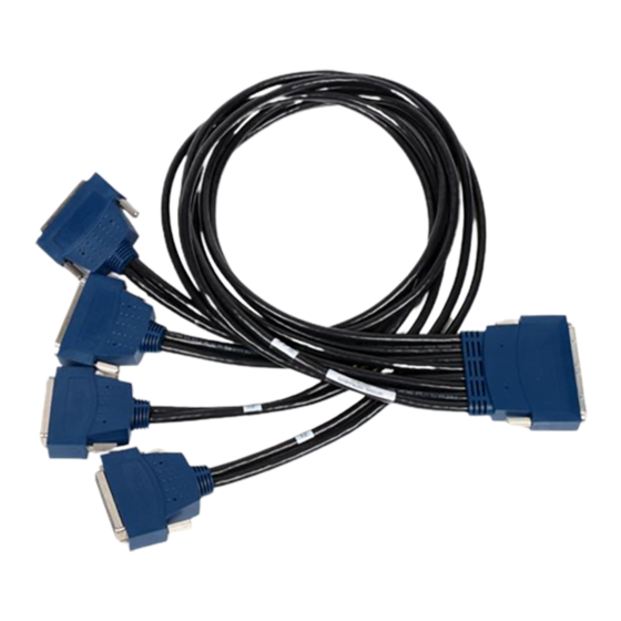
NI PXI-2569/2570/2571/2575 or SCXI-1169/1175 switch module and documentation Connecting the LFH200 Cable Complete the following steps to connect the LFH200 cable to your switch module and application. Refer to Figures 1 and 2 for illustrations of the LFH200 cable. Connect the LFH200 connector to the connector on the switch module. - Page 3 LFH200 Connector Cable Leg Label Thumbscrews 50-Pin Female D-SUB Connectors Figure 1. SH200LFH-4xDB50F-C or SH200LFH-4xDB50F-S Cable LFH200 Connector Cable Leg Label Thumbscrews 25 Unterminated, Tinned, and Stripped Wires Figure 2. SH200LFH-BARE WIRE Cable LFH200 Cable Installation Instructions © National Instruments Corporation...
-
Page 4: Connectors
Connectors The cable in this kit connects an LFH200 connector to four, 50-pin female D-SUB connectors marked P1–P4, or eight bundles, leg J0–J7, of unterminated, tinned, and stripped wires. The LFH200 connector provides connection to the switch module. The 50-pin female D-SUB connectors and unterminated wires provide connection to your application. -
Page 5: Cable Configurations
The SH200LFH-4xDB50F-C cable is recommended for connecting the PXI-2569/2570/2571 or SCXI-1169 to your system. One end of the cable terminates with an LFH200 connector which connects to the switch module. The other end of the cable terminates with four 50-pin female D-SUB connectors. - Page 6 COM51 Figure 7. Twisted Pair Groupings for the PXI-2571 Refer to the NI Switches Help for a complete listing of channel names and pinouts. The following tables list the pin assignments for the SH200LFH-4xDB50F-C cable. LFH200 Cable Installation Instructions ni.com...
- Page 7 NO17 COM33 NO16 NO16 COM31 NO15 NO15 COM29 NO14 NO14 COM27 NO13 NO13 COM25 NO12 NO12 COM23 NO11 NO11 COM21 NO10 NO10 COM19 COM17 COM15 COM13 COM11 COM9 COM7 COM5 COM3 COM1 LFH200 Cable Installation Instructions © National Instruments Corporation...
- Page 8 COM13 COM13 CH29 COM14 COM14 CH31 COM15 COM15 CH33 COM16 COM16 CH35 COM17 COM17 CH37 COM18 COM18 CH39 COM19 COM19 CH41 COM20 COM20 CH43 COM21 COM21 CH45 COM22 COM22 CH47 COM23 COM23 CH49 COM24 COM24 LFH200 Cable Installation Instructions ni.com...
- Page 9 NC16 NC16 COM30 NC15 NC15 COM28 NC14 NC14 COM26 NC13 NC13 COM24 NC12 NC12 COM22 NC11 NC11 COM20 NC10 NC10 COM18 COM16 COM14 COM12 COM10 COM8 COM6 COM4 COM2 COM0 — NC50 LFH200 Cable Installation Instructions © National Instruments Corporation...
- Page 10 — COM54 CH28 — NO54 CH30 — NC55 CH32 — COM55 CH34 — NO55 CH36 — NC56 CH38 — COM56 CH40 — NO56 CH42 — NC57 CH44 — COM57 CH46 — NO57 CH48 — NC58 LFH200 Cable Installation Instructions ni.com...
- Page 11 NC34 NC34 COM66 NC33 NC33 COM64 NC32 NC32 COM62 NC31 NC31 COM60 NC30 NC30 COM58 NC29 NC29 COM56 NC28 NC28 COM54 NC27 NC27 COM52 NC26 NC26 COM50 NC25 NC25 CH50 — COM58 LFH200 Cable Installation Instructions © National Instruments Corporation...
- Page 12 — NO62 CH78 — NC63 CH80 — COM63 CH82 — NO63 CH84 — NC64 CH86 — COM64 CH88 — NO64 CH90 — NC65 CH92 — COM65 CH94 — NO65 CH96 — — CH98 — — LFH200 Cable Installation Instructions ni.com...
- Page 13 NO34 NO34 COM67 NO33 NO33 COM65 NO32 NO32 COM63 NO31 NO31 COM61 NO30 NO30 COM59 NO29 NO29 COM57 NO28 NO28 COM55 NO27 NO27 COM53 NO26 NO26 COM51 NO25 NO25 CH51 COM25 COM25 LFH200 Cable Installation Instructions © National Instruments Corporation...
- Page 14 COM38 COM38 CH79 COM39 COM39 CH81 — COM40 CH83 — COM41 CH85 — COM42 CH87 — COM43 CH89 — COM44 CH91 — COM45 CH93 — COM46 CH95 — COM47 CH97 — COM48 CH99 — COM49 LFH200 Cable Installation Instructions ni.com...
-
Page 15: Sh200Lfh-4Xdb50F-S Cable
SH200LFH-4xDB50F-S Cable The SH200LFH-4xDB50F-S cable is recommended for connecting the PXI-2575 or SCXI-1175 to your system. One end of the cable terminates with an LFH200 connector. The other end of the cable terminates with four 50-pin female D-SUB connectors. When using the SH200LFH-4xDB50F-S cable with the PXI-2575 or SCXI-1175, the positive and negative leads of a channel form a twisted pair. - Page 16 Twisted COM59 NO29 CH10 CH10+ CH10+ NO29 Pair COM57 NO28 CH105 CH10– CH10– NO28 Twisted COM55 NO27 CH11 CH11+ CH11+ NO27 Pair COM53 NO26 CH106 CH11– CH11– NO26 COM51 NO25 CH194 — CH96– NO25 Paired LFH200 Cable Installation Instructions ni.com...
- Page 17 CH21+ CH21+ Pair COM11 CH116 CH21– CH21– Twisted COM9 CH22 CH22+ CH22+ Pair COM7 CH117 CH22– CH22– Twisted COM5 CH23 CH23+ CH23+ Pair COM3 CH118 CH23– CH23– COM1 — — — Paired LFH200 Cable Installation Instructions © National Instruments Corporation...
- Page 18 Twisted CH41 COM20 CH46 CH46+ CH46+ COM20 Pair CH43 COM21 CH141 CH46– CH46– COM21 Twisted CH45 COM22 CH47 CH47+ CH47+ COM22 Pair CH47 COM23 CH142 CH47– CH47– COM23 CH49 COM24 CH191 — CH96+ COM24 Paired LFH200 Cable Installation Instructions ni.com...
- Page 19 CH34 CH34+ CH34+ COM45 Pair CH93 — CH129 CH34– CH34– COM46 Twisted CH95 — CH35 CH35+ CH35+ COM47 Pair CH97 — CH130 CH35– CH35– COM48 CH99 — CH195 — CH97– COM49 Paired LFH200 Cable Installation Instructions © National Instruments Corporation...
- Page 20 Twisted COM58 NC29 CH58 CH58+ CH58+ NC29 Pair COM56 NC28 CH153 CH58– CH58– NC28 Twisted COM54 NC27 CH59 CH59+ CH59+ NC27 Pair COM52 NC26 CH154 CH59– CH59– NC26 COM50 NC25 CH193 — CH95– NC25 Paired LFH200 Cable Installation Instructions ni.com...
- Page 21 CH69+ CH69+ Pair COM10 CH164 CH69– CH69– Twisted COM8 CH70 CH70+ CH70+ Pair COM6 CH165 CH70– CH70– Twisted COM4 CH71 CH71+ CH71+ Pair COM2 CH166 CH71– CH71– COM0 — — — Paired LFH200 Cable Installation Instructions © National Instruments Corporation...
- Page 22 COM56 Twisted CH40 — CH94 CH94+ CH94+ NO56 Pair CH42 — CH189 CH94– CH94– NC57 Twisted CH44 — COM+ COM+ COM57 Pair CH46 — — COM– COM– NO57 CH48 — CH190 — CH95+ NC58 Paired LFH200 Cable Installation Instructions ni.com...
- Page 23 CH82 CH82+ CH82+ NC65 Pair CH92 — CH177 CH82– CH82– COM65 Twisted CH94 — CH83 CH83+ CH83+ NO65 Pair CH96 — CH178 CH83– CH83– — CH98 — CH192 — CH97+ — Paired LFH200 Cable Installation Instructions © National Instruments Corporation...
-
Page 24: Sh200Lfh-Bare Wire Cable
The SH200LFH-BARE WIRE cable is recommended for connecting the switch module to your system if termination other than 50-pin female D-SUB is required. One end of the cable terminates with an LFH200 connector. The other end of the cable has eight bundles of unterminated, tinned, and stripped wires. - Page 25 Pair BRN/WHT COM57 NO28 CH105 CH10– CH10– NO28 RED/GRN Twisted COM55 NO27 CH11 CH11+ CH11+ NO27 Pair GRN/RED COM53 NO26 CH106 CH11– CH11– NO26 RED/BLU COM51 NO25 CH194 — CH96– NO25 Paired LFH200 Cable Installation Instructions © National Instruments Corporation...
- Page 26 GRY/WHT COM11 CH116 CH21– CH21– WHT/BRN Twisted COM9 CH22 CH22+ CH22+ Pair BRN/WHT COM7 CH117 CH22– CH22– RED/GRN Twisted COM5 CH23 CH23+ CH23+ Pair GRN/RED COM3 CH118 CH23– CH23– RED/BLU COM1 — — — Paired LFH200 Cable Installation Instructions ni.com...
- Page 27 Pair BRN/WHT CH93 — CH129 CH34– CH34– COM46 RED/GRN Twisted CH95 — CH35 CH35+ CH35+ COM47 Pair GRN/RED CH97 — CH130 CH35– CH35– COM48 RED/BLU CH99 — CH195 — CH97– COM49 Paired LFH200 Cable Installation Instructions © National Instruments Corporation...
- Page 28 CH46+ CH46+ COM20 Pair BRN/WHT CH43 COM21 CH141 CH46– CH46– COM21 RED/GRN Twisted CH45 COM22 CH47 CH47+ CH47+ COM22 Pair GRN/RED CH47 COM23 CH142 CH47– CH47– COM23 RED/BLU CH49 COM24 CH191 — CH96+ COM24 Paired LFH200 Cable Installation Instructions ni.com...
- Page 29 Pair BRN/WHT COM56 NC28 CH153 CH58– CH58– NC28 RED/GRN Twisted COM54 NC27 CH59 CH59+ CH59+ NC27 Pair GRN/RED COM52 NC26 CH154 CH59– CH59– NC26 RED/BLU COM50 NC25 CH193 — CH95– NC25 Paired LFH200 Cable Installation Instructions © National Instruments Corporation...
- Page 30 GRY/WHT COM10 CH164 CH69– CH69– WHT/BRN Twisted COM8 CH70 CH70+ CH70+ Pair BRN/WHT COM6 CH165 CH70– CH70– RED/GRN Twisted COM4 CH71 CH71+ CH71+ Pair GRN/RED COM2 CH166 CH71– CH71– RED/BLU COM0 — — — Paired LFH200 Cable Installation Instructions ni.com...
- Page 31 Pair BRN/WHT CH92 — CH177 CH82– CH82– COM65 RED/GRN Twisted CH94 — CH83 CH83+ CH83+ NO65 Pair GRN/RED CH96 — CH178 CH83– CH83– — RED/BLU CH98 — CH192 — CH97+ — Paired LFH200 Cable Installation Instructions © National Instruments Corporation...
- Page 32 CH94 CH94+ CH94+ NO56 Pair BRN/WHT CH42 — CH189 CH94– CH94– NC57 RED/GRN Twisted CH44 — COM+ COM+ COM57 Pair GRN/RED CH46 — — COM– COM– NO57 RED/BLU CH48 — CH190 — CH95+ NC58 Paired LFH200 Cable Installation Instructions ni.com...
-
Page 33: Accessories
UL and CSA in North America and IEC and VDE in Europe. Refer to Table 18 for information about third-party accessories for the LFH200 Cable. Table 18. Third-Party Accessories for the LFH200 Cable... -
Page 34: Specifications
Time delay............1.60 ns/ft maximum Time delay skew ..........0.040 ns/ft maximum Attenuation Differential ..........0.025 dB/ft maximum at 5 MHz Single-ended ..........0.085 dB/ft maximum at 50 MHz Conductor DC resistance ........0.070 Ω/ft maximum at 20 °C Gauge ..............28 AWG LFH200 Cable Installation Instructions ni.com... - Page 35 Instruments Patents Notice at ni.com/patents. Refer to the Export Compliance Information at ni.com/legal/export-compliance for the National Instruments global trade compliance policy and how to obtain relevant HTS codes, ECCNs, and other import/export data. © 2004–2011 National Instruments Corporation. All rights reserved.
Need help?
Do you have a question about the LFH200 and is the answer not in the manual?
Questions and answers