Advertisement
Quick Links
Side
JAPANESE
A
Side
ENGLISH
B
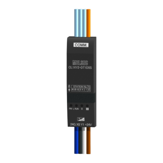
CL1XY2-DT1D5S
CC-Link/LT Remote I/O Module
Please read this manual thoroughly before starting to use the product and
handle the product properly.
User's Manual
MODEL
CL1XY2-DT1D5S
MANUAL Number
JY997D03801K
Date
August 2017
●SAFETY PRECAUTIONS●
(Read these precautions before using.)
Please read this manual carefully and pay special attention to safety in order
to handle this product properly. Also pay careful attention to safety and handle
the module properly.
These precautions apply only to Mitsubishi equipment. Refer to the user's
manual of the CPU module to use for a description of the PLC system safety
precautions.
●
●
These
SAFETY PRECAUTIONS
classify the safety precautions into two
categories: "WARNING" and "CAUTION".
Procedures which may lead to a dangerous condition
and cause death or serious injury if not carried out
properly.
Procedures which may lead to a dangerous condition
and cause superficial to medium injury, or physical
damage only, if not carried out properly.
Depending on circumstances, procedures indicated by
be linked to serious results.
In any case, it is important to follow the directions for usage.
Store this manual in a safe place so that you can take it out and read it
whenever necessary. Always forward it to the end user.
[DESIGN PRECAUTIONS]
• Configure an interlock circuit in a sequence program so that the system operates on the safety
side using the communication status information in the event the data link falls into a
communication problem.
Otherwise, erroneous output and malfunction may result in accidents.
• Remote input and output can not be switched ON or OFF when a problem occurs in the remote
I/O modules. Therefore build an external monitoring circuit that will monitor any input signals that
could cause a serious accident.
• Do not have control cables and connection cables bundled with or placed near by the main
circuit and/or power cables. Wire those cables at least 100mm(3.94 inch) away from the main
circuit and/or power cables. It may cause malfunction due to noise interference.
• Use the module in the status in which any force is not applied on the module, flat cables
dedicated to CC-Link/LT and flat cables for I/O.
If a force is applied, wire breakage or failure may be caused.
[INSTALLATION PRECAUTIONS]
• Use the module in an environment that meets the general specifications contained in this
manual. Using this module in an environment outside the range of the general specifications
could result in electric shock, fire, erroneous operation, and damage to or deterioration of the
product.
• Do not directly touch the module's conductive parts. Doing so could cause malfunction or trouble
in the module.
[WIRING PRECAUTIONS]
• Perform installation and wiring after disconnecting the power supply at all phases externally. If
the power is not disconnected at all phases an electric shock or product damage may result.
• Perform correct wiring for the module according to the product's rated voltage and terminal
arrangement. Connecting to a power supply different from rating or miss-wiring may cause fire,
product failure or malfunction.
• Make sure foreign objects do not get inside the module, such as dirt and wire chips. It may cause
fire, product failure or malfunction.
• Do not short-circuit the 24G and +24V terminals. It may result in fire, product failure or
malfunction.
• Attach a warning label (hazard symbol 417-IEC-5036) concerning the electric shock to the
location.
Side
B
[STARTING AND MAINTENANCE PRECAUTIONS]
• Do not touch the terminals when the power is ON. It may cause an electric shock or malfunction.
• Perform cleaning the module after turning OFF the all external power supply for sure. Failure to do so
may cause failure or malfunction of the modules.
• Do not disassemble or modify the module. Doing so may cause failure, malfunction, injury, or fire.
• The module case is made of resin; do not drop it or subject it to strong shock. A module damage may
result.
• Make sure to switch all phases of the external power supply OFF before installing or removing the
module to/from the panel. Failure to do so may cause failure or malfunction of the modules.
[DISPOSAL PRECAUTIONS]
• When disposing of this product, treat it as industrial waste.
[TRANSPORTATION AND MAINTENANCE PRECAUTIONS]
• During transportation avoid any impact as the module is a precision instrument. Doing so could cause
trouble in the module.
• If is necessary to check the operation of module after transportation, in case of any impact damage.
●Notification of CE marking●
This notification does not guarantee that an entire mechanical module produced
in accordance with the contents of the notification comply with the following
standards. Compliance to EMC standards of the entire mechanical module
should be checked by the user / manufacturer.
Attention
This product is designed for use in industrial applications.
Standards with which this product complies
Type : Programmable Controller (Open Type Equipment) Remote I/O module
Models : Products manufactured:
from November 1st, 2002 to April 30th, 2006 are compliant with
EN61000-6-4 and EN61131-2:1994+A11:1996+A12:2000
after May 1st, 2006 are compliant with EN61131-2:2007
Electromagnetic Compatibility
Standards (EMC)
may also
EN61000-6-4:2001
Compliance with all relevant aspects of
Electromagnetic compatibility
the standard.
-Generic standards - Emission standard
(Radiated Emissions and Mains
for Industrial environment
Terminal Voltage Emissions)
Compliance with all relevant aspects of
the standard.
EN61131-2:1994/A11:1996/A12:2000
• Radiated electromagnetic field
Programmable controllers
• Fast transient burst
-Equipment requirements and tests
• Electrostatic discharge
• Damped oscillatory wave
Compliance with all relevant aspects of
the standard.
EMI
• Radiated Emission
• Conducted Emission
EN61131-2: 2007
EMS
Programmable controllers
• Radiated electromagnetic field
-Equipment requirements and tests
• Fast transient burst
• Electrostatic discharge
• High-energy surge
• Voltage drops and interruptions
• Conducted RF
• Power frequency magnetic field
For more details please contact the local Mitsubishi Electric sales site.
• Notes for compliance to EMC regulation.
It is necessary to install the CL1 series module in a shielded metal control
panel.
*1
• Use this product in Zone A
as defined in EN61131-2.
*1 Zone defined in EN61131-2
Separation defined in EN61131-2 for EMC LVD regulation decided
depending on condition in industrial setting.
Zone C = Factory mains which is isolated from public mains by dedicated
transformers.
Zone B = Dedicated power distribution which is protected by secondary
surge protection. (300 V or less in the rated voltage is
assumed.)
Zone A = Local power distribution which is isolated from dedicated power
distribution by AC/DC converters, isolation transformers, etc.
(120 V or less in the rated voltage is assumed.)
1.
Outline of Product
This product is a cable type composite I/O module connected to CC-Link/LT.
This product has one input point (24 V DC) and one output point (transistor
output).
2.
Name and Setting of Each Part
DIP switch
(Remove the switch cover
when setting the DIP switch.)
DIP switch assignment
40 20 10 8 4 2 1
HLD
Status indicator LEDs
LED name
Operation
PW
Lit while the
power is supplied.
L RUN
Lit while normal
operation is
Blue
executed.
Remark
Name
Status indicator
PW
ON while the power is supplied.
LED
L RUN ON while normal operation is executed.
ON while the input or output is ON.
Extinguished while the input or output is OFF.
I/O operation
indicator LED
X0 input operation
24G
Flat cable
DB
Connector for CC-Link/LT communication line/
dedicated to CC-
module power supply
DA
Link/LT
+24V
Blue
24G
Black
X0
Flat cable for I/O
White Y0
Brown +24V
Set the 10's digit of the station No. using "STATION NO. 10",
"STATION NO. 20" and "STATION NO. 40". Set the 1's digit of
the station No. using "STATION NO. 1", "STATION NO. 2",
"STATION NO. 4" and "STATION NO. 8".
Factory default = All bits are OFF.
Make sure to set the station No. in the range from 1 to 64.
Example: When setting the station No. to "32", set the
DIP switch
DIP switch as follows.
Station
No.
40
32
OFF
Holds the output (when an error has occurred).
HLD
ON: Holds the output.
OFF: Clears the output.
3.
Cautions on Handling
3.1 Handling of flat cable for I/O
The cable length from the module to a sensor shall be within 3m(9'10").
Measure the cable outside the module, and confirm that the driving voltage for
the used sensor is assured.
• Input
Flat cable dedicated
to CC-Link/LT
• Output
Switch cover
(Make sure to attach the
switch cover after setting
the DIP switch.)
Attach it with
this area facing
upward.
If the diameter of the I/O equipment connection cable is equivalent to the
diameter of the flat cable for I/O of this module, connectors dedicated to
CC-Link/LT can be used for connection.
Input
Output
operation
operation
indicator
indicator
LED
LED
Input/output is ON: Lit
Input/output is OFF: Extinguished
Flat cable for I/O
White
Black
Brown
3.2 Handling of cable
Description
Do not bend the cable within 30 mm (1.18 " ) from the module.
30mm(1.19")
0
0
Y0 output operation
indicator LED
indicator LED
Use a crimp-style terminal in a status in which no force is applied on the
cable.
3.3 Mounting with the CL1-HLD (module holder)
Refer to the figures below for details on mounting or removing the remote
I/O module when used with the CL1-HLD.
Mount
CL1-HLD
b)
Remote
I/O
module
a)
10's digit
1's digit
20
10
8
4
2
1
4.
Wiring
ON
ON
OFF
OFF
ON
OFF
4.1 External wiring
The input and output terminals of the CL1XY2-DT1D5S operate while
using the power supplied from the interface.
When connecting a sensor to the input terminal, use a sensor of the NPN
open collector transistor type.
The output wiring is fixed to the sink output.
Crimp-style connection device with
insulator or closed end connection
device
Sensor,
switch, etc.
Crimp-style connection device with
insulator or closed end connection
device
Lamp,
solenoid, etc.
Connector dedicated to CC-Link/LT
Input
equipment
Output
equipment
Wire diameter: AWG18 (34/0.18)
30mm(1.19")
Dismount
1)Fit the remote
a
I/O module in
b
a corner of the
CL1-HLD.
2)Press down b)
while holding
c
a).
d
1)Insert a screwdriver into either a, b, c, or d.
2)Pry the remote I/O module from the
holder using the screwdriver.
Advertisement

Related Manuals for Mitsubishi Electric CL1XY2-DT1D5S


Summary of Contents for Mitsubishi Electric CL1XY2-DT1D5S
- Page 1 • Power frequency magnetic field CL1-HLD. "STATION NO. 20" and "STATION NO. 40". Set the 1's digit of For more details please contact the local Mitsubishi Electric sales site. 2)Press down b) the station No. using "STATION NO. 1", "STATION NO. 2", while holding •...
- Page 2 Notes: does it confer any patent licenses. Mitsubishi Electric Corporation cannot be held by 500V DC insulation resistance tester *3 The module can be used in any environment even outside the control panel as...
- Page 3 DC terminal) and secondary area (internal circuit) module is used in such an environment, it may fail. Notes: does it confer any patent licenses. Mitsubishi Electric Corporation cannot be held by 500V DC insulation resistance tester *1 Bleeder resistor *3 The module can be used in any environment even outside the control panel as...