Table of Contents
Advertisement
SERVICE
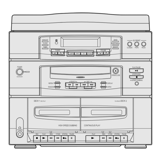
MUSIC CENTER
MONO/ST
CLOCK
TIMER
POWER
ON/STANORY
DECK 1
REC/PLAY
PHONES
REC
PLAY
©
Samsung Electronics Co., Ltd. Aug. 1996.
BAND
PRESET/MANUAL
MEMORY
TUNING
VOLUME
TAPE
PHONO
OPEN/CLOSE
SEARCH
SKIP
REPEAT
DISPLAY
RANDOM
INTRO
DECK 2
PLAYBACK
HIGH SPEED DUBBING
CONTINUOUS PLAY
REW
F.FWD
STOP/EJ
PAUSE
PLAY
REW
F.FWD
STOP/EJ
MUSIC CENTER
SCM-6700
5. Special Circuit Descriptions
EQ PRESET
CLASSIC
POPS
ROCK
PLAY/PAUSE
STOP/CLEAR
HI-SPEED DUBBING
11. Wiring Diagram
PAUSE
Manual
CONTENTS
Code No. AH68-20126A
Advertisement
Table of Contents

Related Manuals for Samsung SCM-6700


Summary of Contents for Samsung SCM-6700
- Page 1 DECK 2 9. Block Diagrams REC/PLAY PLAYBACK 10. PCB Diagrams HIGH SPEED DUBBING CONTINUOUS PLAY PHONES 11. Wiring Diagram PLAY F.FWD STOP/EJ PAUSE PLAY F.FWD STOP/EJ PAUSE 12. Schematic Diagrams © Samsung Electronics Co., Ltd. Aug. 1996. Code No. AH68-20126A...
-
Page 2: Precautions
Examples: Handle brackets, Metal Part metal cabinets, screwheads and control shafts. The current measured should not Ohmmeter exceed 0.5 milliamp. Reverse the power- plug prongs in the AC outlet and repeat. Fig. 1-2 Insulation Resistance Test Samsung Electronics... -
Page 3: Specifications
Make sure that the 8. Always connect a test instrument's ground portion around the serviced part has not lead to the instrument chassis ground been damaged. before connecting the positive lead; always remove the instrument's ground lead last. Samsung Electronics... - Page 4 SCAN : Manufactured for Scandinavian KATSO SATEESEEN! Market. VARNING: OSYNLIG LASERSTRÅLNING NAR DENNA DEL AR OPPNAD OCH SPARREN AR URKOPPLAD BETRAKTA EJSTRÅLEN! Fig. 1-4 Warning Labels (Location: Disc Clamper, Inner Side of Unit Door or Nearby Unit Chassis ) Samsung Electronics...
- Page 5 6. After replacing the Pickup, reopen the Short Terminal. See diagrams below: THE UNIT (1) WRIST-STRAP CONDUCTIVE SHEET FOR GROUNDING short short short short terminal terminal terminal terminal SOH-A1 SOH94T4N SOH91CI(CAR,walkman) (CMS-V10,CMS-V30) SOH91VI(LDP) (CMS-V10,CMS-V30) Samsung Electronics...
- Page 6 Signal to noise ratio 40dB Total harmonic distortion 2.5% Frequency response 20Hz ~ 20KHz(¡ 1dB) Signal to noise ratio 85dB(1kHz 0dB) Compact Disc Channel separation 75dB(1kHz 0dB) Total harmonic distortion 0.1%(1kHz 0dB) * Specifications are subject to change without notice. Samsung Electronics...
-
Page 7: Disassembly And Reassembly
3. Disassembly and Reassembly 3-1 Turn-Table, Cabinet-Front, Cabinet-Bottom 1. Remove Door-CD (Direction A). 2. Release 6 screws !. 3. Remove Turn-Table (Direction B). 4. Release 2 screws @. 5. Release 2 screws #. 6. Remove Front-Cabinet. Figure 3-1 Samsung Electronics... - Page 8 3-2 Deck-CD, Front-PCB, Cassette-Deck, Door-Cassette 1. Release 2 screws !. 2. Remove Deck-CD ASSÕY. 3. Release 4 screws @. 4. Remove Deck-CD. 5. Release 17 screws #. 6. Remove Front-PCB, SUB-PCB. 7. Release 7 screws $. 8. Remove Cassette-Deck. Figure 3-2 Samsung Electronics...
- Page 9 Disassembly and Reassembly 3-3 Cabinet-Bottom and Main-PCB 1. Release 3 screws !. 2. Remove Main-PCB. Figure 3-3 Samsung Electronics...
- Page 10 Disconnect the Lead- Connector assÕy 4 with soldering iron. 7. Remove the AssÕy PCB 3 with soldering iron and remove the PCB-Holder + . 8. Undo 4 screws from the CD-Shaft 7, and remove the CD-Rubber 6 and the CD-Deck ‘ Figure 3-4 Samsung Electronics...
- Page 11 8. Remove the Gear(c) ( by pushing the hook. 9. Lift the Gear(b) ) . 10. Remove the Gear(a) 1 . 11. Remove 2 screws 2 and then remove the Feed-Motor 3 . 12. Remove the Deck(M)-Chassis 4. Figure 3-5 Samsung Electronics...
-
Page 12: Alignment And Adjustments
FM Auto Search Level Adjustment KT431 Oscilloscope FM Stereo Adjustment FM antenna SSG FREQ. 98MHz 50Ω Dummy Adjustment VTVM Speaker point SEMI-VR(5KB) terminal (ISVR2) L-CH/R-CH : Maximum(Figure 4-3) Stereo Modulator (Pilot 10%) Figure 4-3 FM Stereo Separation Adjustment Samsung Electronics... - Page 13 OCT 1 Repeat step 5 and 6 several times DC Voltmeter Input Figure 4-4 AM Frequecny Coverage Adjustment VTVM Oscilloscope AM Signal Test Loop Speaker Generator Antenna Loop Antenna terminal Jack 60 cm Figure 4-5 AM Tracking Adjustment Samsung Electronics...
- Page 14 REC PB Head AZIMUTH Adjustment screw Figure 4-7 Oscilloscope VTVM Speaker Terminal (GND) Figure 4-8 4-2-2 Recording Bias Adjustment Connect frequency counter KC434 and press the REC button. Adjust KT431(BIAS OSC COIL) until frequency counter reads 85¡ 0.2KHz. Samsung Electronics...
- Page 15 Raise NVR1702 and adjust the waveform so that its middle Set NVR1701 to 0mV. comes to GND of the oscilloscope (or until the upper half of waveform becomes symmetrical to the bottom half, A=B) Adjust NVR1704 (arrow) for normal sound. Samsung Electronics...
-
Page 16: Troubleshooting
Connection Pins 73,31 of and soldering UIC1(LC72362) of SCON1-FCW2 is at 5V are normal Voltages at Voltages at RQ1,RQ2 and RQ702,RQ703 RFR1 are normal are normal Voltage at Replae RQ701 Check Voltage at RIC1 RQ701 is normal Samsung Electronics... - Page 17 Check pump charge circuitry Low coverage 0.9V (OQ5) connection of SCON1, High coverage FCW2, FCON1 soldering of pin77 LW Low coverage 0.7V of LC72362N High coverage 4.5V Check loop antenna soldering and connection of OL1, OL2, OT1,OT2, IT2 Samsung Electronics...
- Page 18 Speaker connections are normal Voltages to all pins of AIC1(TA8207) Check power supply section are normal (Refer to Schematic Diagram) Voltage at base of AQ601, Check Muting circuitry AQ651(C945) is less than 0.6V Pattern & Speaker Jack normal Samsung Electronics...
- Page 19 CLOSE S/W. Check oscillation of NXF100 Is Focus Search done properly ? (16.9344MHz). Does Laser function during Replace PICK-UP. Focus Search ? Check NIC9282 pin73 voltage Replace NIC9282. during Focus Search : 5V Replace NIC9220 or NIC9258. Samsung Electronics...
- Page 20 Replace NIC05 Check waveform of NIC9282 Check NIC9282 soldring conditon pins 19,20 Replace NIC9270 Check waveform of NIC9270 Check NIC9270 soldering condition pins 9,12 Replace NIC9270 Check waveform of NIC9270 Check NIC9270 soldering condition pins 2,19 Check Amp. operation Samsung Electronics...
-
Page 21: Exploded Views And Parts List
10000-523-008 AH81-10026P AH81-10025K REEL GEAR ASS’Y 11128-00045AA 10000-607-109 MGARM ASS’Y 11102-00520AA 10000-607-162 AH81-10025T ARM-SENSOR 11102-00530AA AH81-10026L BELT MAIN 59.7 PI X 1.0T 10000-607-117 10000-607-159 AH81-10026H AH81-10025M PAUSE LOCK CAM 11116-00011A 10000-607-111 BELT SUB 34.7 PI X 1.0T 10000-607-128 Samsung Electronics... - Page 22 Exploded Views and Parts List 7-2 Main Exploded View and Parts List 34-1 POWER - PCB POWER - CORD MAIN – PCB FRONT – PCB SUB – PCB POWER TUNER TAPE PHONO SKIP/SEARCH STOP PLAY/PAUSE PROGRAM DISPLAY REPEAT INTRO MONO/ST MEMORY BAND SLEEP...
- Page 23 -,ABS,94HB,BLK,-,SCM6700 AH64-10874B KNOB-PLAY,L SECC,-,T0.8,-,-,SCM6700 AH61-10573A BRACKET-DECK 13014-0378-00 AH61-10576A CHASSIS-MECHA ABS,94HB,-,BLK,-,SCM6700 12201-0174-00 AH62-30107A HEAT-SINK -,AL,-,T6.0,-,WHT,-,SCM6700 12000-0341-00 AH64-30338A CABINET-BOTTOM MIPS,94HB,T3,-,BLK,- AH61-10683A BRACKET-P/T -,SECC,-,T1.0,NTR,-,SCM6700 AH59-90012W ASS’Y-T/T SCM6500 GP150,94HB,T3.0,D/BLU 34-1 AH63-30005A COVER-DUST -,-,-,60,SCM6700 AH59-10080C REMOCON-ASS’Y G3A8-1/C ASS’Y -CD PACK 1-CD G3A8 CKD Samsung Electronics...
- Page 24 AC,-,3500-3800G,2.6-3.2MG0E,30 14014-500-600 AH73-10012A RUBBER-CD SI RUBBER, -, CMS-M5M6C,BLU 16174-503-411 AH61-50182B SHAFT-CD FE,D2.6,L10.5, -, -, 15104-531-710 AH61-60010A SPRING-CAM ES,STS-W,PI0.2,OD3.2,-,CMS-M1 12724-0010-00 3409-000135 SWITCH-LEAF 16V,1A,70GF,SPST B3022-0004 AH31-10021A MOTOR-DC RF-500TB,9VDC/130MA B3070-0002 3409-000175 SWITCH-DETECTOR 30VDC,100MA,SPST 13573-901-050 CMS-P30NM6 DECK-CD CMS-P30NM6 AH61-20227A HOLDER-PCB NYLON66,-,NTR,DAHP-18N,M 13324-0209-00 Samsung Electronics...
- Page 25 AJ30-200013B PICK-UP CDP P/U SOH-A1 ROW V-P/J *SOH-AP AH61-60055A SPRING-T/TABLE CS STS-W PI0.4 D5.7 L9.3 CMS-V10N 12724-0062-00 AH31-10009A MOTOR-SPINDLE RF-310T-11400 43L 25V 85mA 16829-0004-00 AH31-10002B MOTOR-FEED RF-310TA 30MM NDM4RA3ETL 11.0MM 14769-057-250 AH60-10014A SCREW-PH(+M2*3) +M2X3 FE FZY W700 17008-120-032 Samsung Electronics...
- Page 26 PM40030,ABS 10000-451-022 AH81-10020K SPACER ø7.2 X ø15 X T0.5, PE 10000-451-023 AH81-10020L BELT DRIVING PP4029, RC-WRT 10000-451-024 AH81-10020M PLATTER PM20110, M13000TV 10000-451-025 10000-451-026 AH81-10020N E-RING CONNECTOR-5P SC25-05HG 10000-451-027 AH81-10020Q SLIDE SWITCH DSS-1123 10000-451-028 STYLUS CP- 385 -10 10000-451-029 Samsung Electronics...
-
Page 27: Electrical Parts List
R-CARBON;68KOHM,5%,1/8W,AA,TP,1.8X3 11018-877-683 KR435 2001-000034 R-CARBON;220OHM,5%,1/4W,AA,TP,2.4X6 11018-277-221 UR903 2001-000042 R-CARBON;1KOHM,5%,1/4W,AA,TP,2.4X6. 11018-277-102 OR1,2,QR505,555 2001-000273 R-CARBON;100KOHM,5%,1/8W,AA,TP,1.8X 11018-877-104 PR5L,5R,QR503,KR412, 2001-000281 R-CARBON;100OHM,5%,1/8W,AA,TP,1.8X3 11018-877-101 JR32,KR413,409 IR11,OR9,IR12,JR312 2001-000290 R-CARBON;10KOHM,5%,1/8W,AA,TP,1.8X3 11018-877-103 CR821,822,823,824,816 CR826,JR321,371 PR6R,ZR151 AR603,653 2001-000325 R-CARBON;120OHM,5%,1/8W,AA,TP,1.8X3 11018-877-121 OR6,KR432 2001-000331 R-CARBON;12KOHM,5%,1/8W,AA,TP,1.8X3 11018-877-123 JR314 2001-000362 R-CARBON;150OHM,5%,1/8W,AA,TP,1.8X3 11018-877-151 Samsung Electronics... - Page 28 R-CARBON(S);390OHM,5%,1/2W,AA,TP,2. 11018-377-391 RR723,724 2003-000650 R-METAL OXIDE(S);330OHM,5%,2W,AA,TP 11048-577-331 RR710,UR901 2003-000669 R-METAL OXIDE(S);390OHM,5%,1W,AA,TP 11048-477-391 RR711 2008-000127 R-FUSIBLE;10OHM,5%,2W,AA,TP,6.5X17M 11058-577-100 RR701,702,703,707 2008-000157 R-FUSIBLE;4.7OHM,5%,1/4W,AA,TP,2.6X 11058-277-479 ISVR1 2103-000461 VR-SEMI;50KOHM,30%,1/10W,TOP 11249-102-064 CSVR801,ISVR2 2103-000492 VR-SEMI;5KOHM,30%,1/10W,TOP 11249-102-024 2201-000146 C-CERAMIC,DISC;100PF,5%,50V,SL,5X3. 11407-017-101 QC507,557 2201-000377 C-CERAMIC,DISC;220PF,5%,50V,UJ,8.0* 11407-067-221 2201-000557 C-CERAMIC,DISC;470PF,10%,50V,SL,10. 11407-018-471 Samsung Electronics...
- Page 29 C-AL;220UF,20%,16V,GP,8X11.5,3.5MM, UC903,RC709 2401-000830 C-AL;220UF,20%,25V,GP,8*11.5,3.5MM, 11608-104-221 IC12,KC402,452,406,456 2401-001022 C-AL;3.3UF,20%,50V,GP,5*11,2MM, 11608-106-332 JC310,360,QC508,558,505,555 RC701 2401-001052 C-AL;3300UF,20%,25V,GP,16*31.5,7.5M 11609-154-332 UC901 2401-001102 C-AL;330UF,20%,16V,GP,8X11,-, JC311 2401-001364 C-AL;470UF,20%,16V,GP,10X12MM,5MM,T 11608-103-471 RC711 2401-001552 C-AL;47UF,20%,35V,GP,6.3*11,2.5MM, 11608-105-470 IC17,29,QC518,568,522 2401-001895 C-AL;100UF,20%,16V,GP,6.3X11MM,2.5M QC523,RC705,704,710,UC904 IC34,RC706,UC905,AC604,654 IC11,13,27,26,5,OC12 2401-001912 C-AL;1UF,20%,50V,GP,5X11MM,2MM,BK QC501,551,502,552,503,553 QC504,554,521,571 PC1L,1R,2L,2R,AC603,653 QC520,570,RC708,PC1,CC805 KC410 Samsung Electronics...
- Page 30 R-CARBON;390OHM,5%,1/8W,AA,TP,1.8X3 11018-877-391 UR12 2001-000010 R-CARBON;68KOHM,5%,1/8W,AA,TP,1.8X3 11018-877-683 UR50,51,52,55 2001-000273 R-CARBON;100KOHM,5%,1/8W,AA,TP,1.8X 11018-877-104 UR24,11,30,17,43,47 2001-000290 R-CARBON;10KOHM,5%,1/8W,AA,TP,1.8X3 11018-877-103 UR25,31,18 2001-000331 R-CARBON;12KOHM,5%,1/8W,AA,TP,1.8X3 11018-877-123 UR33,34,35,38,39,40 2001-000429 R-CARBON;1KOHM,5%,1/8W,AA,TP,1.8X3. 11018-877-102 UR44,57,58,59,60 2001-000449 R-CARBON;2.2KOHM,5%,1/8W,AA,TP,1.8X 11018-877-222 UR45 2001-000515 R-CARBON;220OHM,5%,1/8W,AA,TP,1.8X3 11018-877-221 UR19,32 2001-000522 R-CARBON;22KOHM,5%,1/8W,AA,TP,1.8X3 11018-877-223 UR36,37 2001-000702 R-CARBON;39KOHM,5%,1/8W,AA,TP,1.8X3 11018-877-393 Samsung Electronics...
- Page 31 AH39-20548A LEAD CONNECTOR-ASSY;-,5264,51088,5P FCW1 AH39-30010A CABLE-IF;-,5264/51088-02,300MM,1365 EYE1 AH59-60001G MODULE-REMOCON;RC-38S2L,38KHZ,-,-,- A1294-0041 LCD1 AH61-20335A HOLDER-CD;ABS,94HB,WHT,T1.5,SCM6700 13323-0263-00 AH67-40024A FILTER-LCD;PC,T0.5,-,-,-,-,WHT,SCM6 10874-0014-00 LAMP1,2,3,4 AH73-10007A RUBBER-CAP;SILICON,-,RCD-1650,GRN AH90-40355A ASSY-OPT PCB FRONT;SCM6700TCE,SEA 2001-001095 R-CARBON(S);2.2MOHM,5%,1/2W,AA,TP,2 11018-377-225 6202-000111 TUBE-VINYL;-,ID5.2,T0.43,-,CLR,PVC, 10659-413-041 AH26-80140H TRANS-POWER;EI60X30,115/230V,60/50H AH39-10001S POWER-CORD;EP2,SPT#2/18,2M,SOLDERIN 13059-808-301 AH61-40022A STUD-TAP;SPC1,T0.5,BT2,-,-, 13124-100-710 Samsung Electronics...
- Page 32 11249-102-043 NC119,120,121,107,108 2203-000199 C-CERAMIC,CHIP;100NF,+80-20%,50V,Z5 NC603 NC205,110,116,102,103 2203-000260 C-CERAMIC,CHIP;10NF,10%,50V,X7R,201 11129-004-103 43R,44L,500,600,601,602 NC700,701 NC1000,1001 2203-000361 C-CERAMIC,CHIP;150PF,5%,50V,NPO,201 NC112 2203-000495 C-CERAMIC,CHIP;2.2NF,10%,50V,X7R,20 11129-004-222 NC118 2203-000787 C-CERAMIC,CHIP;330PF,5%,50V,NPO,201 NC113,125,101 2203-000802 C-CERAMIC,CHIP;33NF,10%,50V,X7R,201 11129-001-333 NC100 2203-000892 C-CERAMIC,CHIP;4.7NF,10%,50V,X7R,20 NC204,124 2203-000925 C-CERAMIC,CHIP;470NF,+80-20%,50V,Y5 11128-018-474 NC200 2203-000979 C-CERAMIC,CHIP;47NF,10%,50V,X7R,201 NC2000 2203-001026 C-CERAMIC,CHIP;4PF,0.25PF,50V,SL,20 Samsung Electronics...
- Page 33 NCW103 3708-000413 CONNECTOR-FPC/FC/PIC;16P,1.25MM,ANG A6010-1525 NCW104 3711-001061 CONNECTOR-HEADER;BOX,6P,1R,2MM,ANGL 13349-139-061 NCW101 3711-001136 CONNECTOR-HEADER;BOX,8P,1R,2MM,ANGL 13349-139-080 3809-000202 CABLE-FLAT;30V,80C,82MM,16P,1MM,UL2 A6032-0066 3811-000130 WIRE-PVC CU;BCWA,300V,60MM,7/0.16MM 13049-011-106 3811-000389 WIRE-NO SHEATH CU;SPCW,300V,52.4MM, A0074-0004 SOLDER-BAR;DONG YANG S63A 30X400 NIC05 AC14-12001G IC;KA78L05,T,- AH62-30047A HEAT SINK;ETHD,-,T0.5,-,-,-,MAX-555 11124-0061-00 AH63-40017A SHIELD-PLATE;SPTE,T0.3,-,MM-77,-, 12074-0024-00 Samsung Electronics...
-
Page 34: Block Diagrams
9. Block Diagrams 9-1 Main Samsung Electronics... -
Page 35: Pcb Diagrams
10. PCB Diagrams 10-1 Main Samsung Electronics 10-1... - Page 36 PCB Diagrams 10-2 Front 10-2 Samsung Electronics...
- Page 37 PCB Diagrams 10-3 CD 10-3-1 Top View 10-3-2 Bottom View Samsung Electronics 10-3...
- Page 38 Block Diagrams 9-2 CD Samsung Electronics...
- Page 39 S 38 S 12 S 37 S 13 S 36 S 14 S 35 S 15 S 34 S 16 S 33 17 18 19 20 21 22 23 24 25 26 27 28 29 30 31 32 Samsung Electronics...
- Page 40 25 CE LC75394E 24 DI LVROUT 23 CL 22 Vss LVRIN 21 L 1 LTOUT 20 NC LINVIN 2 19 L 2 LVref 18 NC LF 5 17 L 3 9 10 11 12 13 14 15 16 Samsung Electronics...
- Page 41 ON OFF SLEEP SLEEP REP.1 REP.1 TUNED TUNED MONO MONO STEREO STEREO TRACK TRACK AUTO AUTO 9 10 11 12 MHz MUTE MHz MUTE OVER OVER VOLUME VOLUME VOLUME VOLUME CLASSIC CLASSIC POPS POPS ROCK ROCK PROGRAM PROGRAM INTRO INTRO RANDOM RANDOM SYNC...
- Page 42 * NOTE : KSB564 ='EBC' TYPE 1 2 3 LB1641/BA6209(MOTOR DRIVER) : NIC1641 LB1641/BA6209 VCC2 OUT1 OUT2 VCC1 8 10 Input logic circuit LB1641 KA9258 : NIC9258 LEVEL SHIFT LEVEL T S D SHIFT REGULATOR MUTE LEVEL LEVEL SHIFT SHIFT Samsung Electronics...
- Page 43 WDCH FSCH & COMPARATOR ARC AMP FDFCT FOCUS RF AMP ERROR AMP LDON FSEO 65 66 67 78 70 71 75 74 69 73 74 76 62 61 68 79 80 1 33 57 56 19 18 17 Samsung Electronics...
- Page 44 SMSD 3RAM ADDRESS LOCK GENERATOR X' TAL XOUT TIMING GENERATOR INTERPOLATE X' TAL C P U MDAT TIMING INTERFACE GENERATOR MCK 38 DIGITAL FILTER (BFS) TRCNT /ISTAT VREFH2 VREFH1 D A C VREFL1 MODE DIGITAL SELECTOR OUTPUT VREFL1 Samsung Electronics...
- Page 45 INDICATE FRAME SYNCHRONIZATION STATUS SOSI SUBCODE SYNCHRONIZATION SIGNAL FUNCTION LED(TUNER) FUNCTION IND LED CONTROL PORT(TUNER) FUNCTION LED(TAPE) FUNCTION IND LED CONTROL PORT(CD) FUNCTION LED(CD) CD B+ CONTROL CD CONTROL FUNCTION IND LED CONTROL PORT(PHONO FUNCTION LED(PHONO or of AUX) AUX) Samsung Electronics...
- Page 46 FM & AM IF FREQUENCY INPUT PORT SUBPD AMIN AM INPUT AM OSC INPUT FMIN FM INPUT FM OSC INPUT TUNER VOLTAGE CONTROL FM TUNING VOLTAGE TUNER VOLTAGE CONTROL AM TUNING VOLTAGE TEST1 Xout OSC 4.5MHZ OSC for SYSTEM CLOCK 9-10 Samsung Electronics...
- Page 47 PCB Diagrams 10-3 CD 10-3-1 Top View 10-3-2 Bottom View Samsung Electronics 10-3...
-
Page 48: Schematic Diagrams
12. Schematic Diagrams 12-1 Main Samsung Electronics 12-1... - Page 49 Schematic Diagrams 12-2 CD 12-2 Samsung Electronics...
Need help?
Do you have a question about the SCM-6700 and is the answer not in the manual?
Questions and answers