
Related Manuals for Allen-Bradley 2080-LC20-20QBB


Summary of Contents for Allen-Bradley 2080-LC20-20QBB
- Page 1 User Manual Micro820 Programmable Controllers Catalog Numbers 2080-LC20-20QWB, 2080-LC20-20QBB, 2080-LC20-20AWB, 2080-LC20-20QWBR, 2080- LC20-20QBBR, 2080-LC20-20AWBR...
- Page 2 IMPORTANT Identifies information that is critical for successful application and understanding of the product. Allen-Bradley, Rockwell Software, Rockwell Automation, Micro800, Micro810, Micro820, Micro830, Micro850, Connected Components Workbench, RSLogix 500, and TechConnect are trademarks of Rockwell Automation, Inc. Trademarks not belonging to Rockwell Automation are property of their respective companies.
-
Page 3: Who Should Use This Manual
Preface Read this preface to familiarize yourself with the rest of the manual. It provides information concerning: • who should use this manual • the purpose of this manual • related documentation • supporting information for Micro800™ Who Should Use this Use this manual if you are responsible for designing, installing, programming, or troubleshooting control systems that use Micro800 controllers. -
Page 4: Additional Resources
Preface Additional Resources These documents contain additional information concerning related Rockwell Automation products. Resource Description Micro800 Plug-in Modules 2080-UM004 Information on features, configuration, installation, wiring, and specifications for the Micro800 plug-in modules. Micro800 Programmable Controllers General Information on instruction sets for developing Instructions 2080-RM001 programs for use in Micro800 control systems. - Page 5 National Electrical Code - Published by the An article on wire sizes and types for grounding National Fire Protection Association of Boston, electrical equipment. Allen-Bradley Industrial Automation Glossary A glossary of industrial automation terms and AG-7.1 abbreviations. You can view or download publications at http://www.rockwellautomation.com/...
- Page 6 Preface Notes: Rockwell Automation Publication 2080-UM005E-EN-E - March 2018...
-
Page 7: Table Of Contents
Table of Contents Preface Who Should Use this Manual ........iii Purpose of this Manual . - Page 8 Table of Contents Chapter 6 Program Execution in Micro800 Overview of Program Execution ........73 Optional Module.
- Page 9 Table of Contents Appendix C Quickstarts Flash Upgrade Your Micro800 Firmware......153 Establish Communications between RSLinx and a Micro820 Controller through USB Port on 2080-REMLCD .
- Page 10 Table of Contents Notes: Rockwell Automation Publication 2080-UM005E-EN-E - March 2018...
-
Page 11: Hardware Features
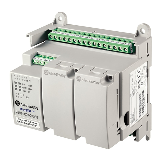
Chapter Hardware Overview This chapter provides an overview of the Micro820 hardware features. It has the following topics: Topic Page Hardware Features Embedded microSD (Micro Secure Digital) Card Slot Embedded RS232/RS485 Serial Port Combo Embedded Ethernet Support Hardware Features Micro820 controllers are 20-point economical brick style controllers with embedded inputs and outputs. - Page 12 ATTENTION: Removable terminal blocks are available on catalog numbers that end in R (for example, 2080-LC20-20QBBR). Fixed terminal blocks are available on catalog numbers that do not end in R (for example, 2080-LC20-20QBB). You can order a replacement terminal block, catalog number 2080-RPL24RTB, separately.
- Page 13 Analog In Family 0…10V DC 0…10V (shared Support 120V AC 120 / 24V DC Relay 24V DC 24V DC with DC In) 240V AC Source Sink Micro820 2080-LC20-20QBB – – – 2080-LC20-20QWB – – – – – 2080-LC20-20AWB – – –...
- Page 14 Chapter 1 Hardware Overview Embedded RS232/RS485 Serial Port Combo The Micro820 controller supports an embedded non-isolated RS232/RS485 combo communications port. Only one port (RS232 or RS485) can work at any given time. The baud rate of this port supports up to 38.4 K. The communication port uses a 6-pin 3.5 mm terminal block with pin definition shown in the following table.
- Page 15 Hardware Overview Chapter 1 Embedded Ethernet Support A 10/100 Base-T Port is available for connection to an Ethernet network through any standard RJ-45 Ethernet cable. RJ-45 Ethernet Port Pin Mapping RJ-45 connector Contact Signal Direction Primary Number Function Transmit data + Transmit data - Receive data + –...
- Page 16 Chapter 1 Hardware Overview Notes: Rockwell Automation Publication 2080-UM005E-EN-E - March 2018...
-
Page 17: Programming Software For Micro800 Controllers
Chapter About Your Controller Programming Software for Connected Components Workbench is a set of collaborative tools supporting Micro800 controllers. It is based on Rockwell Automation and Microsoft Visual Micro800 Controllers Studio technology and offers controller programming, device configuration and integration with HMI editor. Use this software to program your controllers, configure your devices and design your operator interface applications. -
Page 18: Using Run Mode Change (Rmc)
Chapter 2 About Your Controller Using Run Mode Change Run Mode Change (RMC) is a productivity enhancement feature introduced in Release 8 for Micro820/Mico830/Micro850 controllers. It saves the user time by (RMC) allowing logic modifications to a running project without going to remote program mode and without disconnecting from the controller. - Page 19 About Your Controller Chapter 2 ATTENTION: Use extreme caution when you use Run Mode Change. Mistakes can injure personnel and damage equipment. Before using Run Mode Change: · assess how machinery will respond to the changes. · notify all personnel about the changes. A new global variable __SYSVA_PROJ_INCOMPLETE has been added to indicate when Run Mode Changes are being made.
- Page 20 Chapter 2 About Your Controller RMC Memory Run Mode Change (RMC) memory is used to store both the logic and user variable changes made during RMC. The default amount of memory allocated is 2KB and can be increased up to 8KB. However there is still a limit of 2KB for logic and user variables changes per Test Logic.
- Page 21 About Your Controller Chapter 2 If not enough RMC memory is available to make more changes (for example, a “not enough memory” error message appears during RMC build or Test Logic), then a full download must be performed to transfer the incremental changes from the RMC memory to standard user program and data memory.
- Page 22 Chapter 2 About Your Controller Limitations of RMC Take note of the following limitations when using the Run Mode Change (RMC) feature: • Configuration changes cannot be made (for example, change filter times). • Up to 2KB of logic (approximately 150 boolean instructions) and user variables and can be added for each Test Logic.
-
Page 23: Using Run Mode Configuration Change (Rmcc)
About Your Controller Chapter 2 Using Run Mode Run Mode Configuration Change (RMCC) is a productivity enhancement feature introduced in Release 9 for Micro820/Micro830/Micro850 controllers. Configuration Change It allows users to reuse an identical program with multiple controllers simply by (RMCC) changing the address configuration of a controller within the program during run mode. - Page 24 Chapter 2 About Your Controller From firmware revision 10 onwards, Micro820 controllers now retains the address configuration when the controller is power cycled. Set Retained Flag – Modbus Address Set Retained Flag – EtherNet/IP Address Rockwell Automation Publication 2080-UM005E-EN-E - March 2018...
- Page 25 About Your Controller Chapter 2 Using Modbus RTU Communication To use RMCC with the Modbus RTU communication protocol, the serial port must be set to the Modbus slave role. A CIP Generic message is sent from within a program with the following parameters. CIP Generic Message Parameters for RMCC using Modbus RTU Parameter Value...
- Page 26 Chapter 2 About Your Controller When the new node address is configured and applied, the port is not restarted. You must ensure that the new node address being configured is unique IMPORTANT as it will not be checked against existing node addresses of other devices.
- Page 27 About Your Controller Chapter 2 Using EtherNet/IP Communication To use RMCC with the EtherNet/IP communication protocol, the controller must be configured to use a static IP address. If the controller is configured to use BOOTP or DHCP, the change will be rejected. A CIP Generic message is sent from within a program with the following parameters.
-
Page 28: Agency Certifications
Chapter 2 About Your Controller For this example, the new IP Address is set to the following: • IP address = 192.168.1.10 • Subnet mask = 255.255.255.0 • Gateway address = 192.168.1.1 RMCC EtherNet/IP Example – Set the Message Length After the new IP address is configured and applied, the controller will disconnect from Connected Components Workbench if communication is through Ethernet. -
Page 29: Compliance To European Union Directives
EN 61131-2 Programmable Controllers, Part 2 - Equipment Requirements and Tests. For specific information required by EN 61131-2, see the appropriate sections in this publication, as well as the following Allen-Bradley publications: • Industrial Automation Wiring and Grounding Guidelines for Noise Immunity, publication 1770-4.1. -
Page 30: Installation Considerations
Chapter 2 About Your Controller Installation Considerations Most applications require installation in an industrial enclosure (Pollution Degree 2 ) to reduce the effects of electrical interference (Over Voltage Category II ) and environmental exposure. Locate your controller as far as possible from power lines, load lines, and other sources of electrical noise such as hard-contact switches, relays, and AC motor drives. - Page 31 About Your Controller Chapter 2 Environment and Enclosure This equipment is intended for use in a Pollution Degree 2 industrial environment, in overvoltage Category II applications (as defined in IEC 60664-1), at altitudes up to 2000 m (6562 ft) without derating. This equipment is considered Group 1, Class A industrial equipment according to IEC/CISPR 11.
-
Page 32: Safety Considerations
Chapter 2 About Your Controller Safety Considerations Safety considerations are an important element of proper system installation. Actively thinking about the safety of yourself and others, as well as the condition of your equipment, is of primary importance. We recommend reviewing the following safety considerations. - Page 33 About Your Controller Chapter 2 Safety Circuits WARNING: Explosion Hazard Do not connect or disconnect connectors while circuit is live. Circuits installed on the machine for safety reasons, like overtravel limit switches, stop push buttons, and interlocks, should always be hard-wired directly to the master control relay.
-
Page 34: Power Considerations
Chapter 2 About Your Controller Power Considerations The following explains power considerations for the micro controllers. Isolation Transformers You may want to use an isolation transformer in the AC line to the controller. This type of transformer provides isolation from your power distribution system to reduce the electrical noise that enters the controller and is often used as a step- down transformer to reduce line voltage. -
Page 35: Preventing Excessive Heat
About Your Controller Chapter 2 Input States on Power Down The power supply hold-up time as described above is generally longer than the turn-on and turn-off times of the inputs. Because of this, the input state change from “On” to “Off ” that occurs when power is removed may be recorded by the processor before the power supply shuts down the system. - Page 36 Chapter 2 About Your Controller WARNING: Never alter these circuits to defeat their function since serious injury and/or machine damage could result. If you are using an external DC power supply, interrupt the DC output side rather than the AC line side of the supply to avoid the additional delay of power supply turn-off.
- Page 37 About Your Controller Chapter 2 • Install emergency-stop switches and the master control relay in your system. Make certain that relay contacts have a sufficient rating for your application. Emergency-stop switches must be easy to reach. • In the following illustration, input and output circuits are shown with MCR protection.
- Page 38 Chapter 2 About Your Controller Schematic (Using IEC Symbols) 230V AC Disconnect Fuse 230V AC Circuits Isolation Operation of either of these contacts will Transformer remove power from the external I/O Master Control Relay (MCR) circuits, stopping machine motion. 115V AC Cat.
- Page 39 About Your Controller Chapter 2 Schematic (Using ANSI/CSA Symbols) 230V AC Disconnect Fuse 230V AC Output Circuits Isolation Operation of either of these contacts will Transformer remove power from the external I/O Master Control Relay (MCR) circuits, stopping machine motion. 115V AC or Cat.
- Page 40 Chapter 2 About Your Controller Notes: Rockwell Automation Publication 2080-UM005E-EN-E - March 2018...
-
Page 41: Controller Mounting Dimensions
Chapter Install Your Controller This chapter serves to guide the user on installing the controller. It includes the following topics. Topic Page Controller Mounting Dimensions Connect the Controller to an EtherNet/IP Network Module Spacing DIN Rail Mounting Panel Mounting Panel Mounting Dimensions Install the microSD Card Install the 2080-REMLCD Module Controller Mounting... - Page 42 DIN rail. 2. Push the DIN rail latch back into the latched position. Use DIN rail end anchors (Allen-Bradley part number 1492-EAJ35 or 1492-EAHJ35) for vibration or shock environments. To remove your controller from the DIN rail, pry the DIN rail latch downwards until it is in the unlatched position.
-
Page 43: Connect The Controller To An Ethernet/Ip Network
Install Your Controller Chapter 3 Panel Mounting Dimensions Micro820 20-point controllers 2080-LC20-20AWB, 2080-LC20-20QWB, 2080-LC20-20QBB 2080-LC20-20AWBR, 2080-LC20-20QWBR, 2080-LC20-20QBBR 86 mm (3.39 in.) 100 mm (3.94 in.) 46204 Connect the Controller to an EtherNet/IP Network WARNING: If you connect or disconnect the communications cable with power applied to this module or any device on the network, an electrical arc can occur. -
Page 44: Install The Microsd Card
Chapter 3 Install Your Controller Connect the RJ-45 connector of the Ethernet cable to the Ethernet port on the controller. The port is on the bottom of the controller. 46214 Install the microSD Card 1. Insert the microSD card into the card slot. You can install the microSD card in one orientation only. -
Page 45: Install The 2080-Remlcd Module
Install Your Controller Chapter 3 3. To remove the microSD card from the slot, gently press the card until it clicks back and releases itself from the slot. Install the 2080-REMLCD The Micro820 controller supports the 2080-REMLCD module, a simple text display interface for configuring settings such as IP address. - Page 46 Chapter 3 Install Your Controller Notes: Rockwell Automation Publication 2080-UM005E-EN-E - March 2018...
-
Page 47: Wiring Requirements And Recommendation
Chapter Wire Your Controller This chapter provides information on the Micro820 controller wiring requirements. It includes the following sections: Topic Page Wiring Requirements and Recommendation Use Surge Suppressors Recommended Surge Suppressors Grounding the Controller Wiring Diagrams Controller I/O Wiring Minimize Electrical Noise Analog Channel Wiring Guidelines Minimize Electrical Noise on Analog Channels Grounding Your Analog Cable... -
Page 48: Use Surge Suppressors
Chapter 4 Wire Your Controller • Separate wiring by signal type. Bundle wiring with similar electrical characteristics together. • Separate input wiring from output wiring. • Label wiring to all devices in the system. Use tape, shrink-tubing, or other dependable means for labeling purposes. In addition to labeling, use colored insulation to identify wiring based on signal characteristics. - Page 49 Suitable surge suppression methods for inductive AC load devices include a varistor, an RC network, or an Allen-Bradley surge suppressor, all shown below. These components must be appropriately rated to suppress the switching Rockwell Automation Publication 2080-UM005E-EN-E - March 2018...
- Page 50 Output device Output device Surge suppressor RC network Varistor Recommended Surge Suppressors Use the Allen-Bradley surge suppressors in the following table for use with relays, contactors, and starters. Recommended Surge Suppressors Device Coil Voltage Suppressor Catalog Number Type Bulletin 100/104K 700K 24…48V AC...
-
Page 51: Grounding The Controller
Wire Your Controller Chapter 4 Recommended Surge Suppressors Device Coil Voltage Suppressor Catalog Number Type Bulletin 509 Motor Starter Size 6 12…120V AC 199-FSMA1 12…120V AC 199-GSMA1 Bulletin 700 R/RM Relay AC coil Not Required 24…48V DC 199-FSMA9 50…120V DC 199-FSMA10 130…250V DC 199-FSMA11... - Page 52 Chapter 4 Wire Your Controller 2080-LC20-20AWB, 2080-LC20-20QWB, 2080-LC20-20AWBR, 2080-LC20- 20QWBR Input Terminal Block +DC10 I-00 I-02 COM0 I-05 I-07 I-09 I-11 -DC24 I-01 I-03 I-04 I-08 I-10 I-06 Output Terminal Block +DC24 -DC24 O-00 O-01 O-02 O-05 -DC24 VO-0 O-03 O-04 O-06 46212...
- Page 53 Wire Your Controller Chapter 4 ATTENTION: For 2080-LC20-20AWB/R catalogs, inputs 00…03 are limited to 24V DC. All other inputs (04…11) are limited to 120V AC. Digital Input Controller Terminal Input Common Terminal Input Terminal Number Terminal Label Number Label 2080-LC20-20AWB, “-DC24”...
- Page 54 Chapter 4 Wire Your Controller 2080-LC20-20QWB, 2080-LC20-20QWBR DC Sinking Input Configuration – Inputs 00...11 +DC a -DC b +DC b 2080-PSAC12W -DC a +DC10 I-00 I-02 COM0 I-05 I-07 I-09 I-11 -DC24 I-01 I-03 I-04 I-08 I-10 I-06 +DC24 -DC24 O-00 O-01 O-02...
- Page 55 Wire Your Controller Chapter 4 Digital Input Controller Terminal Input Common Terminal Input Terminal Number Terminal Label Number Label 2080-LC20-20QWB, “-DC24” (24V DC sink only) I-00 2080-LC20-20QWBR I-01 I-02 I-03 CM0 (24V DC sink/source) I-04 I-05 I-06 I-07 I-08 I-09 I-10 I-11 Digital Output...
- Page 56 Chapter 4 Wire Your Controller 2080-LC20-20QBB / 2080-LC20-20QBBR Input Terminal Block +DC10 I-00 I-02 COM0 I-05 I-07 I-09 I-11 -DC24 I-01 I-03 I-04 I-08 I-10 I-06 Output Terminal Block +DC24 -DC24 O-00 O-02 -CM0 O-04 O-06 -DC24 VO-0 +CM0 O-01...
- Page 57 +DC c -DC c -DC d Digital Input Controller Terminal Input Common Terminal Input Terminal Number Terminal Label Number Label 2080-LC20-20QBB, “-DC24” (24V DC sink only) I-00 2080-LC20-20QBBR I-01 I-02 I-03 CM0 (24V DC sink/source) I-04 I-05 I-06 I-07 I-08...
- Page 58 Chapter 4 Wire Your Controller Serial Port Terminal Block (View into terminal block) Pin 1 RS485 Data + Pin 2 RS485 Data - Pin 3 RS485 Ground 46213 Pin 4 RS232 Receive Pin 5 RS232 Transmit Pin 6 RS232 Ground (1) Non-isolated.
-
Page 59: Controller I/O Wiring
Wire Your Controller Chapter 4 Controller I/O Wiring This section contains some relevant information about minimizing electrical noise and also includes some wiring examples. Minimize Electrical Noise Because of the variety of applications and environments where controllers are installed and operating, it is impossible to ensure that all environmental noise will be removed by input filters. - Page 60 Chapter 4 Wire Your Controller • use Belden cable #8761 for wiring the analog channels, making sure that the drain wire and foil shield are properly earth grounded. • route the Belden cable separately from any AC wiring. Additional noise immunity can be obtained by routing the cables in grounded conduit.
- Page 61 User side – Load 24V Supply DC COM 45626 For 2080-LC20-20QBB(R) discrete output 06, shielded cable is required if IMPORTANT the output is used as PWM. Otherwise, unshielded cable can be used. Source Input Wiring Example Fuse 45625 Rockwell Automation Publication 2080-UM005E-EN-E - March 2018...
-
Page 62: Wiring Analog Channels
Chapter 4 Wire Your Controller Wiring Analog Channels Analog input circuits can monitor voltage signals and convert them to serial digital data as shown in the following illustration. ATTENTION: Analog inputs and outputs are not isolated. Analog input to sensors Sensor 3 (V) Voltage Sensor 2... - Page 63 Wire Your Controller Chapter 4 Analog input to thermistors Thermistor 3 Thermistor 2 Thermistor 1 Thermistor 0 Note: Terminal block to wire commons is not included in Micro800 package. 46255 +DC10 I-00 I-02 COM0 I-05 I-07 I-09 I-11 -DC24 I-01 I-03 I-04 I-06...
- Page 64 Chapter 4 Wire Your Controller To convert this resistance into a temperature, use the following Steinhart-Hart equation: a + bln(R) + c[ln(R)] Where: Coefficients a, b, and c are provided by the thermistor manufacturer. Calibrate Thermistor 1. Connect a resistor (10 KΩ is recommended) across Vref and Analog Input 00 of your Micro820 controller following the diagram, Analog input to thermistors on...
- Page 65 Wire Your Controller Chapter 4 Transmitters to Analog Input 2-wire Transmitter Controller – I-00, I-01, I-02 or I-03 Power Supply – -DC24 3-wire Transmitter Controller Signal Supply I-00, I-01, I-02 or I-03 Power Supply – -DC24 4-wire Transmitter Controller Supply Signal I-00, I-01, I-02 or I-03 Power...
- Page 66 Chapter 4 Wire Your Controller Notes: Rockwell Automation Publication 2080-UM005E-EN-E - March 2018...
-
Page 67: Overview
Chapter Communication Connections Overview This chapter describes how to communicate with your control system and configure communication settings. The method you use and cabling required to connect your controller depends on what type of system you are employing. This chapter also describes how the controller establishes communication with the appropriate network. - Page 68 Chapter 5 Communication Connections Connection Limits for Micro820 Controllers Description Connections CIP Connections Total number of client plus server connections Maximum number of client connections for all ports Maximum number of server connections for all ports Maximum number of EtherNet/IP connections Client Server Maximum number of USB connections...
- Page 69 Communication Connections Chapter 5 Modbus RTU Modbus is a half-duplex, master-slave communications protocol. The Modbus network master reads and writes bits and registers. Modbus protocol allows a single master to communicate with a maximum of 247 slave devices. Micro800 controllers support Modbus RTU Master and Modbus RTU Slave protocol. For more information on configuring your Micro800 controller for Modbus protocol, refer to the Connected Components Workbench Online Help.
- Page 70 Chapter 5 Communication Connections Modbus TCP Client/Server The Modbus TCP Client/Server communication protocol uses the same Modbus mapping features as Modbus RTU, but instead of the Serial port, it is supported over Ethernet. Modbus TCP Server takes on Modbus Slave features on Ethernet.
- Page 71 Communication Connections Chapter 5 CIP Symbolic Addressing Users may access any global variable through CIP Symbolic addressing except for system and reserved variables. One- or two-dimension arrays for simple data types are supported (for example, ARRAY OF INT[1..10, 1..10]) are supported but arrays of arrays (for example, ARRAY OF ARRAY) are not supported.
-
Page 72: Cip Communications Pass-Thru
Chapter 5 Communication Connections Sockets Client/Server TCP/UDP Sockets protocol is used for Ethernet communications to devices which do not support Modbus TCP and Ethernet/IP. Sockets support client and server, and TCP and UDP. Typical applications include communicating to printers, barcode readers, and PCs. -
Page 73: Use Modems With Micro800 Controllers
Communication Connections Chapter 5 EtherNet/IP to DeviceNet EtherNet/IP DeviceNet PowerFlex 525 drive with 25-COMM-D adapter (Address 1) Micro820 controller For program download with 2080-DNET20 plug-in scanner (Address 0) The user can use Connected Components Workbench to configure the PowerFlex drives. CompactBlock LDX I/O (Address 2) Micro800 controllers do not support more than one hop (for example,... -
Page 74: Configure Serial Port
Chapter 5 Communication Connections Configure Serial Port You can configure the Serial Port driver as CIP Serial, Modbus RTU, ASCII or choose Shutdown through the Controller Configuration tree in Connected Components Workbench software. By default, when a Micro820 controller is added to the Project Organizer in Connected Components Workbench, Remote LCD parameters are configured to overwrite serial port settings. - Page 75 Communication Connections Chapter 5 When the Remote LCD configuration is unchecked, the serial port values are visible and can be edited. After changing the serial port settings on the controller, power cycle the IMPORTANT Remote LCD. Configure CIP Serial Driver 1.
- Page 76 Chapter 5 Communication Connections 2. Select CIP Serial from the Driver field. 3. Specify a baud rate. Select a communication rate that all devices in your system support. Configure all devices in the system for the same communication rate. Default baud rate is set @ 38400 bps. 4.
- Page 77 Received embedded responses only when it detects embedded responses from another device, choose After One Received. If you are communicating with another Allen-Bradley device, choose Enabled Unconditionally. Embedded responses increase network traffic efficiency. NAK Retries The number of times the controller will resend a message packet because the processor received a NAK response to the previous message packet transmission.
- Page 78 Chapter 5 Communication Connections 2. Select Modbus RTU on the Driver field. 3. Specify the following parameters: • Baud rate • Parity • Unit address • Modbus Role (Master, Slave, Auto) Modbus RTU Parameters Parameter Options Default Baud Rate 1200, 2400, 4800, 9600, 19200, 38400 19200 Parity None, Odd, Even...
- Page 79 Communication Connections Chapter 5 Configure ASCII 1. Open your Connected Components Workbench project. On the device configuration tree, go to Controller properties. Click Serial Port. 2. Select ASCII on the Driver field. 3. Specify baud rate and parity. ASCII Parameters Parameter Options Default...
-
Page 80: Configure Ethernet Settings
Chapter 5 Communication Connections Configure Ethernet Settings 1. Open your Connected Components Workbench project (for example, Micro820). On the device configuration tree, go to Controller properties. Click Ethernet. 2. Under Ethernet, click Internet Protocol. Configure Internet Protocol (IP) settings. Specify whether to obtain the IP address automatically using DHCP or manually configure IP address, subnet mask, and gateway address. - Page 81 Communication Connections Chapter 5 4. Under Ethernet, click Port Settings. 5. Set Port State as Enabled or Disabled. 6. To manually set connection speed and duplexity, uncheck the option box Auto-Negotiate speed and duplexity. Then, set Speed (10 or 100 Mbps) and Duplexity (Half or Full) values.
-
Page 82: Opc Support Using Rslinx Enterprise
Chapter 5 Communication Connections Ethernet Host Name Micro800 controllers implement unique host names for each controller, to be used to identify the controller on the network. The default host name is comprised of two parts: product type and MAC address, separated by a hyphen. For example: 2080LC20-xxxxxxxxxxxx, where xxxxxxxxxxxx is the MAC address. -
Page 83: Overview Of Program Execution
Chapter Program Execution in Micro800 This section provides a brief overview of running or executing programs with a Micro800 controller. This section generally describes program execution in Micro800 IMPORTANT controllers. Certain elements may not be applicable or true in certain models (for example, Micro820 does not support PTO motion control). -
Page 84: Optional Module
Chapter 6 Program Execution in Micro800 In addition to the User Fault Routine, Micro800 controllers also support two Selectable Timed Interrupts (STI). STIs execute assigned programs once every set point interval (1…65535 ms). The Global System Variables associated with cycles/scans are: •... -
Page 85: Controller Load And Performance Considerations
Program Execution in Micro800 Chapter 6 ATTENTION: If the optional module feature is enabled, use the MODULE_INFO instruction to verify that the module is present because the controller will not fault if the module is missing. Controller Load and Within one program scan cycle, the execution of the main steps (as indicated in the Execution Rules diagram) could be interrupted by other controller activities Performance which have higher priority than the main steps. -
Page 86: Power Up And First Scan
Chapter 6 Program Execution in Micro800 Power Up and First Scan In Program mode, all analog and digital input variables hold their last state, and the LEDs are always updated. Also all analog and digital output variables hold their last state, but only the analog outputs hold their last state while the digital outputs are off. -
Page 87: Memory Allocation
Program Execution in Micro800 Chapter 6 Memory Allocation Depending on base size, available memory on Micro800 controllers are shown in the table below. Memory Allocation for Micro800 Controllers Attribute 10/16-point 20-point 24- and 48-points Program steps 10 K 10 K Data bytes 8 KB 20 KB... - Page 88 Chapter 6 Program Execution in Micro800 Example of Five Nested UDFBs UDFB1 UDFB2 UDFB3 UDFB4 UDFB5 • Structured Text (ST) is much more efficient and easier to use than Ladder Logic, when used for equations. If you are used to using the RSLogix 500® CPT Compute instruction, then a great alternative is to use ST combined with either UDF or UDFB.
-
Page 89: Exclusive Access
Chapter Controller Security Micro800 security generally has two components: • Exclusive Access which prevents simultaneous configuration of the controller by two users • Controller Password Protection which secures the Intellectual Property contained within the controller and prevents unauthorized access Exclusive Access Exclusive access is enforced on the Micro800 controller regardless of whether the controller is password-protected or not. -
Page 90: Compatibility
Chapter 7 Controller Security Compatibility The Controller Password feature is supported on: • Connected Components Workbench revision 2 and later • Micro800 controllers with at least revision 2 firmware For users with earlier versions of the software and/or hardware, refer to the compatibility scenarios below. -
Page 91: Work With A Locked Controller
Controller Security Chapter 7 Work with a Locked The following workflows are supported on compatible Micro800 controllers (firmware revision 2) and Connected Components Workbench software Controller revision 2. Upload from a Password-Protected Controller 1. Launch the Connected Components Workbench software. 2. - Page 92 Chapter 7 Controller Security 6. Click Download. 7. Click Disconnect. If the controller has a password locked revision 10 or later project, you IMPORTANT cannot access the controller using Connected Workbench software revision 9 or earlier. If you use Connected Components Workbench software revision 10 or later to download a revision 9 or earlier project, the password in the controller will be automatically converted to the old algorithm.
-
Page 93: Configure Controller Password
Controller Security Chapter 7 Back Up and Restore a Password-Protected Controller In this workflow, user application will be backed up from a Micro800 controller that is locked to a memory plug-in device. 1. In the Project Organizer, click the Discover icon. The Browse Connections dialog appears. -
Page 94: Recover From A Lost Password
Chapter 7 Controller Security Recover from a Lost If the controller is secured with a password and the password has been lost, then it is impossible to access the controller using the Connected Components Password Workbench software. To recover, the controller must be set to Program Mode using the keyswitch for Micro830 and Micro850 controllers, the 2080-LCD for Micro810 controllers, or the 2080-REMLCD for Micro820 controllers. -
Page 95: Overview
Chapter Using the Micro800 Remote LCD This chapter provides a description of how you can use the Micro800 Remote LCD with the Micro820 controller. It has the following sections. Topic Page Overview Text Display Mode USB Mode Backup and Restore Hardware Features, Installation, and Specifications ASCII Code for Special Characters Overview... -
Page 96: Usb Mode
Chapter 8 Using the Micro800 Remote LCD Micro800 Remote LCD 3.5-inch LCD screen Keypad USB port MENU RS232 serial port for connectivity to the controller The 2080-REMLCD module is IP65-rated and can be mounted through the front panel or on the same DIN rail as the Micro820 controller. It has two modes of operation: •... -
Page 97: Text Display Mode
Using the Micro800 Remote LCD Chapter 8 Using the USB port is convenient when accessing the controller from the IMPORTANT front of the cabinet without opening the door and when the IP address is unknown. For larger programs, it is recommended to use USB port through the Remote LCD to set the IP address and then use Ethernet to download. - Page 98 Chapter 8 Using the Micro800 Remote LCD After showing the startup message, the Remote LCD will show the I/O Status screen, assuming that no LCD_REM instructions are executing. Navigate the Remote LCD In text display mode, you can make use of available navigation keys (function keys, arrow keys, ESC and OK) to navigate through the menus.
- Page 99 Using the Micro800 Remote LCD Chapter 8 The Main Menu shows the following screen: Mode Switch 14:18WED Variables I/O Status The following structure tree takes you through the different menus available in the Remote LCD module and their general description. 2080-REMLCD Menu Structure Tree Mode Switch Set the controller to Program...
- Page 100 Chapter 8 Using the Micro800 Remote LCD Main Menu Items Menu Item Description I/O Status Shows the status of the local I/O. Mode switch Change the mode switch selection. Variables View and change the data value of a variable. Using Connected Components Workbench software, you can specify which variables in the program can be viewed and edited through the 2080-REMLCD module.
- Page 101 Using the Micro800 Remote LCD Chapter 8 Shows how many bytes (out of 400 allowed) have been used up User-defined Screens To create user-defined screens through Connected Components Workbench, you can program the Remote LCD module using the following function blocks. 2080-REMLCD Function Blocks Function Block Name Description...
- Page 102 Chapter 8 Using the Micro800 Remote LCD LCD_REM The LCD_REM function block is used to display user strings on the REMLCD module when REMLCD is present and connected. LCD_REM Enable LCD_REM Font Line 1 Line 2 Line 3 Line 4 Line 5 Line 6 Line 7...
-
Page 103: Backup And Restore
Using the Micro800 Remote LCD Chapter 8 KEY_READ_REM KEY_READ_REM Enable KEY_READ_REM KeyData This function block can be used to read key status on the Remote LCD module when the user-defined screen is active. When user-defined screen is not active, KEY_READ_REM instruction flags an error. Note that the KEY_READ_REM instruction will always show key status as False if Push Button Key Read is disabled in Connected Components Workbench or the Remote LCD. - Page 104 Chapter 8 Using the Micro800 Remote LCD Filled box (without border) Horizontal parallel lines (without border) Vertical parallel lines (without border) Horizontal line cap right (without border) Horizontal line cap left (without border) Vertical line cap up (without border) Vertical line cap down (without border) Up arrow (with border) Down arrow (with border) Right arrow (with border)
- Page 105 Using the Micro800 Remote LCD Chapter 8 1/2 filled box right (without border) 3/4 filled box right (without border) 1/4 filled box upside down (without border) 1/2 filled box upside down (without border) 3/4 filled box upside down (without border) 1/4 filled box upside (without border) 1/2 filled box upside (without border) 3/4 filled box upside (without border)
- Page 106 Chapter 8 Using the Micro800 Remote LCD Notes: Rockwell Automation Publication 2080-UM005E-EN-E - March 2018...
-
Page 107: Overview
Chapter Using microSD Cards This chapter provides a description of microSD card support on Micro820 controllers. Topic Page Overview Project Backup and Restore Backup and Restore Directory Structure Powerup Settings in ConfigMeFirst.txt General Configuration Rules in ConfigMeFirst.txt ConfigMeFirst.txt Errors Data Log Recipe Quickstart Projects for Data Log and Recipe Function Blocks The last section provides quickstart projects for the data log and recipe functions. -
Page 108: Project Backup And Restore
Chapter 9 Using microSD Cards Project Backup and Project backup and restore on Micro820 controllers are mainly supported through the microSD card. Both backup and restore can be initiated or manually Restore triggered and configured through the Connected Components Workbench, the 2080-REMLCD module, and the ConfigMeFirst.txt file in the microSD card. - Page 109 Using microSD Cards Chapter 9 Backup and restore can be configured to trigger through the following ways: Method Backup Restore Online with Connected Components Workbench 2080-REMLCD Project configuration on Load Always and/or Load on memory card at powerup Memory Error options ConfigMeFirst.txt at powerup (Through the [BKD] command)
- Page 110 Chapter 9 Using microSD Cards Project restore is done from the subdirectory specified in ConfigMeFirst.txt file or the Micro820/USERPRJ default folder, if none is specified in the ConfigMeFirst.txt file. The user needs to ensure that the directory is populated with correct contents before restoring. The ConfigMeFirst.txt file is a configuration file stored on the microSD card that the user can optionally create to customize backup, restore, recipe and data log directories.
- Page 111 Using microSD Cards Chapter 9 ConfigMeFirst.txt Configuration Settings Setting Description [SNM = xxx.xxx.xxx.xxx] Power up and set subnet mask to xxx (must be numbers only). [GWA = xxx.xxx.xxx.xxx] Power up and set gateway address to xxx (must be numbers only). [END] End of setting.
- Page 112 Chapter 9 Using microSD Cards Sample ConfigMeFirst.txt File General Configuration Rules in ConfigMeFirst.txt • All settings must be in upper case and enclosed in brackets [ ]. • Each line must contain only one setting. • Settings must always appear first in a line. •...
- Page 113 Using microSD Cards Chapter 9 Deliver Project Updates to Customers Through Email A benefit of using the project backup and restore feature is to allow you to deliver project updates to customers through email. You can do so by following the example shown below.
- Page 114 Chapter 9 Using microSD Cards Send image files through email The next step is to retrieve the image files from the microSD card and send them to your customer through email. 1. Remove the microSD card from the controller and read the card using your computer.
- Page 115 Using microSD Cards Chapter 9 Restore project from backup The last step is to restore the project to your controller from the microSD card. There are two methods to restore the backup, depending on the configuration of the controller. Existing Controller - Load Always / Load on Error For this example, the Load on power up setting was configured to “Load Always”.
-
Page 116: Data Log
Chapter 9 Using microSD Cards Data Log The data logging feature allows you to capture global and local variables with timestamp from the Micro800 controller into the microSD card. You can retrieve the recorded datasets on the microSD card by reading the contents of the microSD card through a card reader or by doing an upload through the Connected Components Workbench software. - Page 117 Using microSD Cards Chapter 9 Data Log Directory Structure The DATALOG folder is created under the current project directory in the microSD card. In this example, the current project directory is MYPROJECT. By default, the current project directory name is taken from the downloaded project’s controller name or from the ConfigMeFirst.txt.
- Page 118 Chapter 9 Using microSD Cards Data Log Function (DLG) Block The data logging function block lets a user program to write run-time global values into the data logging file in microSD card. Enable Status TSEnable ErrorID CfgId DLG Input and Output Parameters Parameter Parameter Data Type Description...
- Page 119 Using microSD Cards Chapter 9 DLG Function Block Errors Status Code Name Description DLG_ERR_CFG_FORMAT Data log configuration file format is wrong. DLG_ERR_RTC Real time clock is invalid. DLG_ERR_UNKNOWN Unspecified error has occurred. File access error will be returned during DLG function block execution IMPORTANT when card is full.
- Page 120 Chapter 9 Using microSD Cards Data Log Function Block Execution IMPORTANT • There are three possible states for the Data Log function block: Idle, Busy and Complete (which includes Complete with Succeed and Complete with Error). • For one Data Log function block execution, the typical status starts from Idle, then Busy and finishes with Complete.
-
Page 121: Recipe
Using microSD Cards Chapter 9 Supported Data Types for Data Log and Recipe Function Blocks Data Type Description Example format in output data log file REAL 32-bit floating point value -3.40282347E+38, +3.40282347E+38 LREAL 64-bit floating point value -1.7976931348623157E+308, +1.7976931348623157E+308 STRING character string '"Rotation Speed"... - Page 122 Chapter 9 Using microSD Cards Recipe Directory Structure On first execution of RCP, it creates the RECIPE folder under the current project directory on the microSD card. It also creates 10 subdirectories for each recipe set with a name following the CfgID input value (1…10) . If the CfgID value is 1, then the subfolder Rcp_Id01 is created.
- Page 123 Using microSD Cards Chapter 9 RCP Input and Output Parameters Parameter Parameter Data Type Description Type Enable INPUT BOOL Recipe read/write function enable. If Rising Edge (Enable is triggered from "low" to "high"), starts recipe function block and the precondition is that last operation is completed.
- Page 124 Chapter 9 Using microSD Cards RCP Function Block Errors Error ID Error name Description RCP_ERR_DATAFILE_ABSENT Recipe data file is absent. RCP_ERR_DATAFILE_FORMAT Recipe data file contents are wrong. RCP_ERR_DATAFILE_SIZE Recipe data file size is too big (>4K). File access error will be returned during RCP function block execution IMPORTANT when card is full.
-
Page 125: Quickstart Projects For Data Log And Recipe Function Blocks
Using microSD Cards Chapter 9 RCP Function Block Execution IMPORTANT • There are three possible states for Recipe function block: Idle, Busy, Complete (Complete with Succeed and Complete with Error) • For one Recipe function block execution, the typical status starts from Idle then Busy and finishes with Complete. - Page 126 Chapter 9 Using microSD Cards Use the Data Log Feature Configure data log Create data log ladder program Build and download Execute DLG function block Upload data log file Configure data log 1. In Connected Components Workbench, go to the Properties pane to configure your data log.
- Page 127 Using microSD Cards Chapter 9 Create data log ladder program 1. Launch Connected Components Workbench. Create a user program for your Micro820 controller. 2. Right-click Programs. Select Add New LD: Ladder Diagram. Name the Program (for example, Prog1). 3. From the Toolbox, double-click Direct Contact to add it to the rung. 4.
- Page 128 Chapter 9 Using microSD Cards 5. On the Block Selector window that appears, type DLG to filter the DLG function block from the list of available function blocks. Click OK. 6. Create the following local variables for your project. Local Variables Variable Name Data Type EnDlg...
- Page 129 Using microSD Cards Chapter 9 7. Assign the variables to the DLG input and output parameters as follows: Note: For CfgID input parameter, you can choose a predefined variable by choosing from the Defined Words in Connected Components Workbench. To do so, click the CfgID input box.
- Page 130 Chapter 9 Using microSD Cards Build and download After configuring data log properties, build the program and download to the controller. Execute DLG function block Execute the DLG function block. Notice the Status output go from 0 (Idle) to 1 (Enable), and 2 (Succeed). Upload data log file You can retrieve data log files from the microSD card using a card reader or by uploading the data logs through Connected Components Workbench.
- Page 131 Using microSD Cards Chapter 9 The Manage button is not available in DEBUG mode. You need to stop IMPORTANT DEBUG mode to use the Manage button to upload data log files. Uploading data log files in PROGRAM mode is recommended for performance and file locking reasons.
- Page 132 Chapter 9 Using microSD Cards Use the Recipe Feature Configure Recipe Create Recipe ladder program Build and download Execute RCP function block Upload Recipe files Configure Recipe 1. In Connected Components Workbench, go to the Properties pane to configure Recipe. 2.
- Page 133 Using microSD Cards Chapter 9 Create Recipe ladder program 1. Launch Connected Components Workbench. Create a user program for your Micro820 controller. 2. Right-click Programs. Select Add New LD: Ladder Diagram. Name the Program (for example, Prog2). 3. From the Toolbox, double-click Direct Contact to add it to the first rung. 4.
- Page 134 Chapter 9 Using microSD Cards 5. On the Block Selector window that appears, type RCP to filter the Recipe function block from the list of available function blocks. Click OK. 6. From the Toolbox, double-click rung to add another rung. 7.
- Page 135 Using microSD Cards Chapter 9 9. Assign the variables to the RCP input and output parameters as follows: Rung 1 Rung 2 Note: For CfgID input parameter, you can choose a predefined variable by choosing from the Defined Words in Connected Components Workbench. To do so, click the CfgID input box.
- Page 136 Chapter 9 Using microSD Cards Build and download After configuring Recipe, build the program and download to the controller. Rockwell Automation Publication 2080-UM005E-EN-E - March 2018...
- Page 137 Using microSD Cards Chapter 9 Execute RCP function block Execute the RCP function block. Notice the Status output go from 0 (Idle) to 1 (Enable), and 2 (Succeed). Upload Recipe files You can retrieve recipe files from the microSD card using a card reader or by uploading the recipe files through Connected Components Workbench.
- Page 138 Chapter 9 Using microSD Cards 3. From the Upload window that appears, select the batch of recipe files that you would like to upload. 4. If the file already exists in your destination folder, select whether you would like to Overwrite file, Skip file, or Preserve both Files. 5.
-
Page 139: General Specifications
0.22…0.25 Nm (1.95…2.21 lb-in.) using 0.4 x 2.5 x 80 mm 2-component grip with non-slip grip screwdriver. Input circuit type 24V DC sink/source (standard) – for 2080-LC20-20QWB(R), 2080-LC20-20QBB(R) 120V AC – for 2080-LC20-20AWB(R) for inputs 4…11 only Output circuit type... - Page 140 Chapter A Specifications General Specifications Attribute 2080-LC20-20AWB(R) 2080-LC20-20QBB(R) 2080-LC20-20QWB(R) Power dissipation Power supply voltage range 20.4…26.4 V DC, Class 2 Auxiliary power supply output for thermistor I/O rating Input: 120V AC 16 mA Input: 24V DC, 8.8 mA Input: 24V DC, 8.8 mA...
- Page 141 Off-state current, max 2.5 mA Inrush current, max 250 mA @ 125V AC Inrush decay time constant, max 22 ms DC Input Filter Settings for I-04…I-11 for 2080-LC20-20QWB(R), 2080-LC20-20QBB(R) Nominal Filter Minimum ON Maximum ON Minimum OFF Maximum OFF Setting (ms)
- Page 142 12-bit, 2.5 mV/count Output update rate (with no output capacitance), max 20 ms Channel-to-bus isolation No isolation Channel-to-channel isolation No isolation DC Output Specifications for 2080-LC20-20QBB(R) Attribute Standard Outputs High Speed Output (Outputs O-00…O-05) (Output O-06) User supply voltage 10V DC, min 10V DC, min 26.4V DC, max...
- Page 143 Specifications Chapter A DC Output Specifications for 2080-LC20-20QBB(R) Attribute Standard Outputs High Speed Output (Outputs O-00…O-05) (Output O-06) Current ratings per point 0.3 A @ 65 °C, max 100 mA (high speed 1.0 A @ 30 °C, max operation) 1.0 mA, max leakage 1.0 A @ 30 °C...
- Page 144 Chapter A Specifications 0.25 0.15 Positive Error Negative Error 0.05 -0.05 1000 100000 10000 Frequency PWM Typical Readings PWM Typical Readings Expected Duty Cycle Typical Duty Cycle (1.27 KΩ load) Frequency (kHz) %Duty Cycle Minimum Maximum %Duty Cycle 4.90% 6.25% 5.48 9.90% 11.25%...
- Page 145 Specifications Chapter A PWM Typical Readings Expected Duty Cycle Typical Duty Cycle (1.27 KΩ load) Frequency (kHz) %Duty Cycle Minimum Maximum %Duty Cycle 9.50% 16.25% 12.3 19.50% 26.25% 22.4 39.50% 46.25% 42.3 54.50% 61.25% 57.3 64.50% 71.25% 67.3 84.50% 91.25% 87.3 94.50% 100.00%...
- Page 146 Chapter A Specifications Data Log Performance Data Log – Data Payload vs. Performance Time Parameter Number of Characters 1028 1493 3676 Average write time per data log 541.77 ms 1043.75 ms 1086.67 ms 1632.36 ms 1972.9 ms 2696.22 ms file including all overheads Average write time excluding first 500.40 ms 963.86 ms...
-
Page 147: Environmental Specifications
Specifications Chapter A 2900 Time (msec) 2400 Average write time per data log including all overheads 1900 Average write time excluding first sample 1400 Average write time excluding all overheads Data Payload 518-characters 1028-characters 1493-characters 3676-characters 28-characters 502-characters Environmental Environmental Specifications Specifications Attribute Value... -
Page 148: Certifications
Chapter A Specifications Environmental Specifications Attribute Value Radiated RF immunity IEC 61000-4-3: 10V/m with 1 kHz sine-wave 80% AM from 80…2000 MHz 10V/m with 200 Hz 50% Pulse 100% AM @ 900 MHz 10V/m with 200 Hz 50% Pulse 100% AM @ 1890 MHz 10V/m with 1 kHz sine-wave 80% AM from 2000…2700 MHz EFT/B immunity IEC 61000-4-4:... -
Page 149: Status Indicators On The Controller
Appendix Troubleshooting Status Indicators on the Status indication on the Micro820 controller is as follows. Controller Input status Run status Fault status Force status Comm status ENET status SD status Output status 46207 Status Indicator Description Description State Indicates Input status Input is low. - Page 150 Appendix B Troubleshooting Status Indicator Description Description State Indicates SD status • microSD card is not inserted. Uninitialized State • microSD card is inserted but medium is bad. • microSD card is inserted but file system is bad. • microSD card read/write failure. Error State •...
-
Page 151: Error Codes
Appendix B Troubleshooting Error Codes This section lists possible error codes for your controller, as well as recommended actions for recovery. Information about the fault is stored in a fault log, which can be accessed from the Diagnostics page in Connected Components Workbench software. - Page 152 Appendix B Troubleshooting List of Error Codes for Micro800 controllers Error Code Fault Type Description Recommended Action 0xF000 Recoverable The controller was unexpectedly reset due to a Perform one of the following: noisy environment or an internal hardware • See Corrective Actions for Recoverable Faults on page 149.
- Page 153 Appendix B Troubleshooting List of Error Codes for Micro800 controllers Error Code Fault Type Description Recommended Action 0xF010 Recoverable The user program contains a function/function Perform one of the following: block that is not supported by the Micro800 • See Corrective Actions for Recoverable Faults on page 149.
- Page 154 Appendix B Troubleshooting List of Error Codes for Micro800 controllers Error Code Fault Type Description Recommended Action 0xF023 Non- The controller program has been cleared. This Perform one of the following: recoverable happened because: • See Corrective Actions for Non-recoverable Faults on page 149.
- Page 155 Appendix B Troubleshooting List of Error Codes for Micro800 controllers Error Code Fault Type Description Recommended Action 0xF27z Recoverable A non-recoverable communication fault has Perform one of the following: occurred on the expansion I/O module. • See Corrective Actions for Recoverable Faults on page 149.
- Page 156 Appendix B Troubleshooting List of Error Codes for Micro800 controllers Error Code Fault Type Description Recommended Action 0xF0Az Recoverable The plug-in I/O module experienced an error Perform the following: during operation. • Check the condition and operation of the plug-in I/O module. •...
- Page 157 Appendix B Troubleshooting List of Error Codes for Micro800 controllers Error Code Fault Type Description Recommended Action 0xF0878 Recoverable An index used to access a bit is beyond the Perform the following: boundaries of the data type it is used on. 1.
- Page 158 Appendix B Troubleshooting List of Error Codes for Micro800 controllers Error Code Fault Type Description Recommended Action 0xFFzz Recoverable A user-created fault from Connected Components Corrective Actions for Recoverable Faults on page 149. Workbench has occurred. 0xD00F Recoverable A particular hardware type (for example, Corrective Actions for Recoverable Faults on page 149.
-
Page 159: Retrieve A Fault Log
Appendix B Troubleshooting Corrective Action for Recoverable and Non-recoverable Faults Corrective Actions for Recoverable Faults Perform the following: 1. Optionally save the fault log from Connected Components Workbench software. For more information, refer to Retrieve a Fault Log on page 149. 2. -
Page 160: Controller Error Recovery Model
Appendix B Troubleshooting Controller Error Recovery Use the following error recovery model to help you diagnose software and hardware problems in the micro controller. The model provides common Model questions you might ask to help troubleshoot your system. Refer to the recommended pages within the model for further help. -
Page 161: Calling Rockwell Automation For Assistance
Appendix B Troubleshooting Calling If you need to contact Rockwell Automation or local distributor for assistance, it is helpful to obtain the following (prior to calling): Rockwell Automation for • controller type, series letter, revision letter, and firmware (FRN) number of Assistance the controller •... -
Page 162: Rockwell Automation Publication 2080-Um005E-En-E - March
Appendix B Troubleshooting Notes: Rockwell Automation Publication 2080-UM005E-EN-E - March 2018... -
Page 163: Flash Upgrade Your Micro800 Firmware
Appendix Quickstarts This chapter covers some common tasks and quickstart instructions that are aimed to make you familiar with the in Connected Component Workbench. The following quickstarts are included: Topic Page Flash Upgrade Your Micro800 Firmware Establish Communications between RSLinx and a Micro820 Controller through USB Port on 2080-REMLCD Configure Controller Password Forcing I/Os... - Page 164 Appendix C Quickstarts On Micro820 controllers, users can use flash update their controllers through the Ethernet port, in addition to the USB of the 2080-REMLCD. To successfully flash update your controller over USB, connect only one IMPORTANT controller to your computer, and do not perform the flash update in a virtual machine such as VMware.
- Page 165 Quickstarts Appendix C If the desired firmware revision is not shown in the drop-down list, you can download that firmware revision by clicking the “Get the firmware files online” link. You can also change the Connection Path by clicking the “Change” link. 4.
- Page 166 Appendix C Quickstarts After control flashing the controller, some microSD cards may not be IMPORTANT detected. Remove and insert the microSD card, or power cycle the controller if this issue is encountered. Flash Upgrade From MicroSD Card With Connected Components Workbench release 8.0 onwards, you can flash upgrade your Micro820 controller from the microSD card in addition to using ControlFLASH.
- Page 167 Quickstarts Appendix C The SD Card Utility window appears. 3. Select the drive letter that points to the microSD card on your computer from the pull-down list. You can check the drive letter by looking in Windows Explorer. For this example, the microSD card is using the drive letter “G”.
- Page 168 Appendix C Quickstarts 5. Select the firmware revision you want to flash your Micro820 controller with. The list of firmware revisions are installed together with Connected Components Workbench. If you require a revision that is not listed, download the firmware from the Product Compatibility and Download Center (PCDC) at http://www.rockwellautomation.com/rockwellautomation/support/ pcdc.page...
- Page 169 Quickstarts Appendix C Step 2 – Edit the ConfigMeFirst.txt File To flash upgrade the controller with the firmware that you have transferred to the microSD card, you need to edit the ConfigMeFirst.txt file with the settings listed below. These settings must be added at the beginning of the file. New ConfigMeFirst.txt Configuration Settings for Flash Upgrade Setting Description...
-
Page 170: Through Usb Port On
Appendix C Quickstarts For a list of firmware and series compatibility, see the release notes for firmware revision 11.011 or later, publication 2080-RN004. Establish Communications This quick start shows you how to get RSLinx RSWho to communicate with a Micro820 controller through USB. Micro820 controller uses the between RSLinx and a 2080_REMLCD_xxxx driver Micro820 Controller... - Page 171 Quickstarts Appendix C 4. Click Install the software automatically (Recommended), and then click Next. The Wizard searches for new hardware. Rockwell Automation Publication 2080-UM005E-EN-E - March 2018...
- Page 172 Appendix C Quickstarts 5. Open RSLinx Classic and run RSWho by clicking the icon. 6. On the EDS Wizard that appears, click Next to continue. 7. Follow the prompts to upload and install the EDS file. Rockwell Automation Publication 2080-UM005E-EN-E - March 2018...
- Page 173 Quickstarts Appendix C Rockwell Automation Publication 2080-UM005E-EN-E - March 2018...
-
Page 174: Configure Controller Password
Appendix C Quickstarts 8. Click Finish to complete. Configure Controller Set, change, and clear the password on a target controller through the Connected Components Workbench software. Password The following instructions are supported on Connected Components IMPORTANT Workbench revision 2 and Micro800 controllers with firmware revision 2. For more information about the controller password feature on Micro800 controllers, see Controller Security on page... - Page 175 Quickstarts Appendix C Set Controller Password After creating or changing the controller password, you need to power IMPORTANT down the controller in order for the password to be saved. In the following instructions, the Connected Components Workbench software is connected to the Micro800 controller. 1.
- Page 176 Appendix C Quickstarts 4. The Set Controller Password dialog appears. Provide password. Confirm the password by providing it again in the Confirm field. Passwords must have at least eight characters to be valid. 5. Click OK. Once a password is created, any new sessions that try to connect to the controller will have to supply the password to gain exclusive access to the target controller.
- Page 177 Quickstarts Appendix C 2. The Change Controller Password dialog appears. Enter Old Password, New Password and confirm the new password. 3. Click OK. The controller requires the new password to grant access to any new session. Clear Password With an authorized session, you can clear the password on a target controller through the Connected Components Workbench software.
-
Page 178: Forcing I/Os
Appendix C Quickstarts Forcing I/Os This section generally talks about forcing I/O in Micro800 controllers. IMPORTANT Some elements may not apply to certain models (for example, Micro810 and Micro820 controllers do not support PTO motion). Inputs are logically forced. LED status indicators do not show forced values, but the inputs in the user program are forced. - Page 179 Quickstarts Appendix C Remember you cannot force a Physical Input and cannot force a Logical Output. In many cases, the front of the controller is not visible to the operator and Connected Components Workbench is not online with the controller. If you want the force status to be visible to the operator, then the User Program must read the force status using the SYS_INFO function block and then display the force status on something that the operator can see, such as the human machine...
-
Page 180: Using Run Mode Change
Appendix C Quickstarts Using Run Mode Change Run Mode Change allows the user to make small changes to the logic of a running project and immediately testing it out on the controller, without having to go into Program mode or disconnecting from the controller. The following requirements must be met to use Run Mode Change: IMPORTANT •... - Page 181 Quickstarts Appendix C 4. Double -click the newly added Direct Coil to bring up the Variable Selector dialog and select “_IO_EM_DO_00”. 5. Build the project. 6. Download the project to the controller. In the Connection Browser dialog, select the Micro850 controller. 7.
- Page 182 Appendix C Quickstarts 8. Select Download to confirm. 9. When the project has been downloaded to the controller, a prompt asking to change the controller to Remote Run mode appears. Click Yes. 10. Observe that the controller is now in Debug mode. From Connected Components Workbench version 8.0 onwards, IMPORTANT selecting “Yes”...
- Page 183 Quickstarts Appendix C Edit the Project Using Run Mode Change Run Mode Change Toolbar Run Mode Change Test Logic Changes Accept Changes Undo Changes 1. Click the Run Mode Change icon. Observe that the controller goes into Edit mode and is still connected. If you add a new variable during RMC, external data access and changing the access type (default is Read/Write) of this new variable is not available until you have chosen to Accept or Undo the Test Logic changes.
- Page 184 Appendix C Quickstarts 3. Double-click the newly added Instruction Block and select “Timer On/Off “(TONOFF). Configure the Instruction Block to trigger every one second. 4. From the Toolbox, double-click Reverse Contact to add it to the rung, or drag and drop Reverse Contact onto the run. Place it to left of the recently added Instruction Block.
- Page 185 Quickstarts Appendix C 5. Click the Test Logic Changes icon to build the project and download it to the controller. When a Test Logic is performed, or undoing changes after the IMPORTANT Test Logic is completed, any active communication instructions will be aborted while the changes are downloaded to the controller.
- Page 186 Appendix C Quickstarts Observe that original project is shown and the controller is in Debug mode. To Accept the Changes 1. Click the Accept Changes icon. 2. Observe that only the Run Mode Change icon is now enabled and the controller remains in Debug mode.
-
Page 187: Appendix D
Appendix PID Function Blocks The PID function block has parameter naming similar to RSLogix 500 and is recommended for users who are already familiar with programming in RSLogix 500. The IPIDCONTROLLER function block has the advantage of supporting auto tune. Comparison Between IPIDCONTROLLER and PID IPIDCONTROLLER Description... -
Page 188: Pid Function Block
Appendix D PID Function Blocks Comparison Between IPIDCONTROLLER and PID IPIDCONTROLLER Description Auto – TRUE = Normal operation of PID. FALSE = Output tracks Feedback. Feedback Feedback of the control being applied to the process. Usually it’s the PID’s CV after any limits or manual control has been applied. - Page 189 PID Function Blocks Appendix D PID Arguments Parameter Parameter Data Type Description Type CVMin Input REAL Control value minimum limit. If CV < CVMin, then CV = CVMin. If CVMin > CVMax, and error occurs. CVMax Input REAL Control value maximum limit. If CV >...
- Page 190 Appendix D PID Function Blocks GAIN_PID Data Type Parameter Parameter Data Type Description Type Input REAL Time integral constant in seconds (>= 0.0001). Increasing Ti decreases overshoot and oscillation of the PID. If Ti is invalid, an error occurs. Input REAL Time derivative constant in seconds (>= 0.0).
-
Page 191: Ipidcontroller Function Block
PID Function Blocks Appendix D IPIDCONTROLLER Function This function block diagram shows the arguments in the IPIDCONTROLLER function block. Block IPIDCONTROLLER IPIDCONTROLLER Output Process SetPoint AbsoluteError FeedBack ATWarning Auto OutGains Initialize Gains AutoTune ATParameters The following table explains the arguments used in this function block. IPIDCONTROLLER Arguments Parameter Parameter... - Page 192 Appendix D PID Function Blocks IPIDCONTROLLER Arguments Parameter Parameter Data Type Description Type ATWarnings Output DINT Warning for the AutoTune sequence. Possible value are: 0 = No auto tune done. 1 = In auto tune mode. 2 = Auto tune done. -1 = Error 1: Input automatically set to TRUE, no auto tune possible.
- Page 193 PID Function Blocks Appendix D GAIN_PID Data Type Parameter Type Description TimeIntegral REAL Time integral value for PID (>= 0.0001). Time integral value for PID A smaller integral time constant causes a faster change in the output based upon the difference between the PV (measured process value) and SV (set point value) integrated over this time.
-
Page 194: How To Autotune
Appendix D PID Function Blocks How to Autotune Before you autotune, you need to: • Verify that your system is constant when there is no control. For example, for temperature control, process value should remain at room temperature when there is no control output. •... -
Page 195: Troubleshooting An Autotune Process
PID Function Blocks Appendix D 5. Calculate deviation value with reference to the fluctuation. For example, if the temperature stabilizes around 22 °C (72 °F) with a fluctuation of 21.7…22.5 °C (71…72.5 °F), the value of ‘ATParams.Deviation’ is: 72.5 - 71 22.5 - 21.7 = 0.75 = 0.4... -
Page 196: Pid Application Example
Appendix D PID Function Blocks Output Sequence 1: 50 -> 70 -> 30 Sequence Condition Autotune Result Action for Autotune Fail Process value reached 'first peak' and Likely successful 'second' peak in time Output Sequence 2: 50 -> 70 -> 50 Sequence Condition Autotune Result Action for Autotune Fail... - Page 197 PID Function Blocks Appendix D electric RC lead network. The energy storage element for these systems are heat energy, potential energy, rotational kinetic energy and capacitive storage energy, respectively. This may be written in a standard form such as f(t) = τdy/dt + y(t), where τ is the system time constant, f is the forcing function and y is the system state variable.
- Page 198 Appendix D PID Function Blocks a pre-defined function block, IPIDCONTROLLER, and four user-defined function blocks. These four are: • PID_OutputRegulator This user-defined function block regulates the output of IPIDCONTROLLER within a safe range to ensure that there is no damage to the hardware used in the process. IF RMIN ≤...
-
Page 199: Modbus Mapping
Appendix Modbus Mapping for Micro800 Modbus Mapping All Micro800 controllers (except the Micro810 12-point models) support Modbus RTU over a serial port through the embedded, non-isolated serial port. The 2080-SERIALISOL isolated serial port plug-in module also supports Modbus RTU. Both Modbus RTU master and slave are supported. Although performance may be affected by the program scan time, the 48-point controllers can support up to six serial ports (one embedded and five plug-ins), and so consequently, six separate Modbus networks. - Page 200 Appendix E Modbus Mapping for Micro800 Variable Data Type 0 - Coils 1 - Discrete Inputs 3 - Input Registers 4 - Holding Registers 000001 to 065536 100001 to 165536 300001 to 365536 400001 to 465536 Supported Modbus Supported Modbus Supported Modbus Supported...
- Page 201 Modbus Mapping for Micro800 Appendix E 1. Change from DF1 to Modbus protocol. 2. Set the Address of Micro800 slave to match the serial port configuration for the controller. 3. Deactivate Tags on Error. This is to prevent the requirement of power cycling PVC when new Modbus Mappings are downloaded from Connected Components Workbench to Micro800 controller.
- Page 202 Appendix E Modbus Mapping for Micro800 Parameter numbers listed in this section are for a PowerFlex 4M and will be different if you are using another PowerFlex 4-Class drive. Parameter Name Parameter Number 400N 400P Start Source P106 Speed Reference P108 Comm Data Rate C302...
- Page 203 Modbus Mapping for Micro800 Appendix E 6. The Parameter window opens. Resize it to view the parameters. From this window, you can view and set data values of Parameters. 7. From the Parameter window, change the following Parameters to set the communications for Modbus RTU so that the PowerFlex 4M Drive will communicate with Micro830/850 via Modbus RTU communication.
- Page 204 Appendix E Modbus Mapping for Micro800 8194 Speed Reference word xxx.x format for 4/4M/40, where "123" = 12.3 Hz xxx.xx format for 40P/400/400N/400P, where "123" = 1.23 Hz 8449 Logic Status word (Read, Active, Fault, and so on.) 8452 Speed Feedback word (uses same format as Speed Reference) 8450 Error Code word (n+1)
- Page 205 Index Symbols __SYSVA_CYCLECNT 74 backup 1 __SYSVA_TCYCURRENT 74 baud rate 4 __SYSVA_TCYMAXIMUM 74 before calling for assistance 151 BOOL 61 Numerics 2080-LCD 79 2080-MEMBAK-RTC 1 calibration 53 2080-PS120-240VAC 32 calling for assistance 151 2080-REMLCD 1 CE mark 19 advanced set 89 certifications 18 analog calibration 90 Checking if Forces (locks) are Enabled 168...
- Page 206 Index controller password 79 execution rules 106 ControlLogix 60 Fault status 2 data log 1 Force status 2 data types 110 force status 139 directory structure 107 Forcing I/Os 168 execution rules 110 specifications 107 timing diagram 109 data types 61 general considerations 20 datasets 106 grounding the controller 41...
- Page 207 Index KEY_READ_REM 91 NAK retries 67 keyswitch 84 Normal Operation 140 North American Hazardous Location Approval 22 LCD_BKLT_REM 91 LCD_REM 91 outputs LINT 61 embedded 1 Overview of Program Execution 73 Literature Library 35 LREAL 61 panel mounting 32 PanelView Component 60 Mapping Address Space and supported Data Types 189 parity 66 master control relay 25...
- Page 208 Index periodic tests 23 periodic tests of master control relay circuit 23 REAL 61 power distribution 23 recipe 1 safety circuits 23 data types 110 security 79 directory structure 112 serial communications status 139 function block errors 113 serial port function block parameters 112 configure 64 function block status 113...
- Page 209 Index validate IP address 71 variable retainment 76 voltage input 53 wiring 37 fixed terminal blocks 38 removable terminal blocks 38 RS232/RS485 terminal block 38 wiring diagrams 41 Wiring Examples 51 wiring recommendation 37 Wiring Your Controller 37 Rockwell Automation Publication 2080-UM005E-EN-E - March 2018...
- Page 210 Index Notes: Rockwell Automation Publication 2080-UM005E-EN-E - March 2018...
- Page 211 Rockwell Automation Publication 2080-UM005E-EN-E - March 2018...
- Page 212 Rockwell Automation Support Rockwell Automation provides technical information on the Web to assist you in using its products. At http://www.rockwellautomation.com/support/, you can find technical manuals, a knowledge base of FAQs, technical and application notes, sample code and links to software service packs, and a MySupport feature that you can customize to make the best use of these tools.
Need help?
Do you have a question about the 2080-LC20-20QBB and is the answer not in the manual?
Questions and answers