
Related Manuals for Allen-Bradley 2080-LC20-20QWB


Summary of Contents for Allen-Bradley 2080-LC20-20QWB
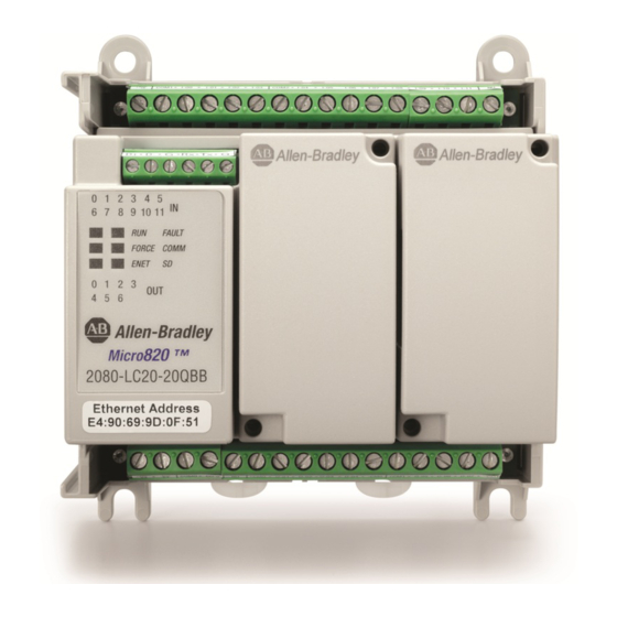
- Page 1 User Manual Micro820 Programmable Controllers Catalog Numbers 2080-LC20-20QWB, 2080-LC20-20QBB, 2080-LC20-20AWB, 2080-LC20-20QWBR, 2080- LC20-20QBBR, 2080-LC20-20AWBR...
- Page 2 Identifies information that is critical for successful application and understanding of the product. IMPORTANT Allen-Bradley, Rockwell Software, Rockwell Automation, Micro800, Micro820, Micro830, Micro850, Connected Components Workbench, and TechConnect are trademarks of Rockwell Automation, Inc. Trademarks not belonging to Rockwell Automation are property of their respective companies.
-
Page 3: Who Should Use This Manual
Preface Read this preface to familiarize yourself with the rest of the manual. It provides information concerning: • who should use this manual • the purpose of this manual • related documentation • supporting information for Micro800™ Who Should Use this Use this manual if you are responsible for designing, installing, programming, or troubleshooting control systems that use Micro800 controllers. - Page 4 National Electrical Code - Published by the An article on wire sizes and types for grounding National Fire Protection Association of Boston, electrical equipment. Allen-Bradley Industrial Automation Glossary A glossary of industrial automation terms and AG-7.1 abbreviations. You can view or download publications at http://www.rockwellautomation.com/...
-
Page 5: Table Of Contents
Table of Contents Preface Who Should Use this Manual ........iii Purpose of this Manual . - Page 6 Table of Contents Chapter 6 Program Execution in Micro800 Overview of Program Execution ........61 Controller Load and Performance Considerations .
- Page 7 Chapter 1 Appendix C Quickstarts Flash Upgrade Your Micro800 Firmware......133 Establish Communications between RSLinx and a Micro820 Controller through USB Port on 2080-REMLCD .
- Page 8 Table of Contents Notes: viii Rockwell Automation Publication 2080-UM005B-EN-E - March 2015...
-
Page 9: Hardware Features
Chapter Hardware Overview This chapter provides an overview of the Micro820 hardware features. It has the following topics: Topic Page Hardware Features Embedded microSD (Micro Secure Digital) Card Slot Embedded RS232/RS485 Serial Port Combo Embedded Ethernet Support Hardware Features Micro820 controllers are 20-point economical brick style controllers with embedded inputs and outputs. - Page 10 Chapter 1 Hardware Overview For information on the REMLCD module, see Using the Micro800 Remote LCD on page The controller also accommodates any class 2 rated 24V DC output power supply that meets minimum specifications such as the optional Micro800 power supply.
- Page 11 0…10V (shared Support 120V AC 120 / 24V DC Relay 24V DC 24V DC with DC In) 240V AC Source Sink Micro820 2080-LC20-20QBB – – – 2080-LC20-20QWB – – – – – 2080-LC20-20AWB – – – – 2080-LC20-20QBBR – – –...
- Page 12 Chapter 1 Hardware Overview RS232/RS485 Serial Port Pin Definition Definition RS485 RS232 Example Example RS485+ RS485+ (not used) RS485- RS485- (not used) RS232 input (receiver) (not used) RS232 output (driver) (not used) The communication port (both RS232 and RS485) are non-isolated. The signal ground of the port is not isolated to the logic ground of the controller.
- Page 13 Hardware Overview Chapter 1 Ethernet port pin-to-pin connection white-orange orange white-green blue white-blue green white-brown brown white-orange orange white-green blue white-blue green white-brown 46223 brown Troubleshooting on page 123 for descriptions of ENET status indicator. Rockwell Automation Publication 2080-UM005B-EN-E - March 2015...
- Page 14 Chapter 1 Hardware Overview Notes: Rockwell Automation Publication 2080-UM005B-EN-E - March 2015...
-
Page 15: Programming Software For Micro800 Controllers
Chapter About Your Controller Programming Software for Connected Components Workbench is a set of collaborative tools supporting Micro800 controllers. It is based on Rockwell Automation and Microsoft Visual Micro800 Controllers Studio technology and offers controller programming, device configuration and integration with HMI editor. Use this software to program your controllers, configure your devices and design your operator interface applications. - Page 16 Chapter 2 About Your Controller RMC is useful when the user is developing a project by incrementally adding small changes to the logic and immediately wants to see the effects of the changes on the machine. With RMC, since the controller stays in remote run mode, the controller logic and machine actuators will not have to constantly reinitialize, which can occur if the controller is switched to remote program mode (for example, first scan bit is checked in program logic to clear outputs).
- Page 17 About Your Controller Chapter 2 When a Test Logic is performed, or undoing changes after the Test Logic IMPORTANT is completed, any active communication instructions will be aborted while the changes are downloaded to the controller. Uncommitted Changes Uncommitted changes are changes made in RMC that have not been accepted or undone after a Test Logic Change has been performed.
- Page 18 Chapter 2 About Your Controller RMC Memory Usage Example Controller Memory RMC Memory (for User Program + Data) (Default size = 2KB) 1st change and 2nd change and 3rd change and Test Logic Test Logic Test Logic (Add logic) (Remove logic) (Add logic) Free memory Free RMC memory...
- Page 19 About Your Controller Chapter 2 Insufficient Controller Memory Example Controller Memory RMC Memory (for User Program + Data) (Default size = 2KB) Free RMC memory Error will occur due to insufficient controller memory remaining Used memory Limitations of RMC Take note of the following limitations when using the Run Mode Change (RMC) feature: •...
-
Page 20: Agency Certifications
EN 61131-2 Programmable Controllers, Part 2 - Equipment Requirements and Tests. For specific information required by EN 61131-2, see the appropriate sections in this publication, as well as the following Allen-Bradley publications: • Industrial Automation Wiring and Grounding Guidelines for Noise Immunity, publication 1770-4.1. -
Page 21: Installation Considerations
About Your Controller Chapter 2 Installation Considerations Most applications require installation in an industrial enclosure (Pollution Degree 2 ) to reduce the effects of electrical interference (Over Voltage Category II ) and environmental exposure. Locate your controller as far as possible from power lines, load lines, and other sources of electrical noise such as hard-contact switches, relays, and AC motor drives. - Page 22 Chapter 2 About Your Controller Environment and Enclosure This equipment is intended for use in a Pollution Degree 2 industrial environment, in overvoltage Category II applications (as defined in IEC 60664-1), at altitudes up to 2000 m (6562 ft) without derating. This equipment is considered Group 1, Class A industrial equipment according to IEC/CISPR 11.
-
Page 23: Safety Considerations
About Your Controller Chapter 2 Safety Considerations Safety considerations are an important element of proper system installation. Actively thinking about the safety of yourself and others, as well as the condition of your equipment, is of primary importance. We recommend reviewing the following safety considerations. - Page 24 Chapter 2 About Your Controller Safety Circuits WARNING: Explosion Hazard Do not connect or disconnect connectors while circuit is live. Circuits installed on the machine for safety reasons, like overtravel limit switches, stop push buttons, and interlocks, should always be hard-wired directly to the master control relay.
-
Page 25: Power Considerations
About Your Controller Chapter 2 Power Considerations The following explains power considerations for the micro controllers. Isolation Transformers You may want to use an isolation transformer in the AC line to the controller. This type of transformer provides isolation from your power distribution system to reduce the electrical noise that enters the controller and is often used as a step- down transformer to reduce line voltage. -
Page 26: Preventing Excessive Heat
Chapter 2 About Your Controller Input States on Power Down The power supply hold-up time as described above is generally longer than the turn-on and turn-off times of the inputs. Because of this, the input state change from “On” to “Off ” that occurs when power is removed may be recorded by the processor before the power supply shuts down the system. - Page 27 About Your Controller Chapter 2 WARNING: Never alter these circuits to defeat their function since serious injury and/or machine damage could result. If you are using an external DC power supply, interrupt the DC output side rather than the AC line side of the supply to avoid the additional delay of power supply turn-off.
- Page 28 Chapter 2 About Your Controller • Install emergency-stop switches and the master control relay in your system. Make certain that relay contacts have a sufficient rating for your application. Emergency-stop switches must be easy to reach. • In the following illustration, input and output circuits are shown with MCR protection.
- Page 29 About Your Controller Chapter 2 Schematic (Using IEC Symbols) 230V AC Disconnect Fuse 230V AC Circuits Isolation Operation of either of these contacts will Transformer remove power from the external I/O Master Control Relay (MCR) circuits, stopping machine motion. 115V AC Cat.
- Page 30 Chapter 2 About Your Controller Schematic (Using ANSI/CSA Symbols) 230V AC Disconnect Fuse 230V AC Output Circuits Isolation Operation of either of these contacts will Transformer remove power from the external I/O Master Control Relay (MCR) circuits, stopping machine motion. 115V AC or Cat.
-
Page 31: Controller Mounting Dimensions
Chapter Install Your Controller This chapter serves to guide the user on installing the controller. It includes the following topics. Topic Page Controller Mounting Dimensions Connect the Controller to an EtherNet/IP Network Module Spacing DIN Rail Mounting Panel Mounting Panel Mounting Dimensions Install the microSD Card Install the 2080-REMLCD Module Controller Mounting... - Page 32 DIN rail. 2. Push the DIN rail latch back into the latched position. Use DIN rail end anchors (Allen-Bradley part number 1492-EAJ35 or 1492-EAHJ35) for vibration or shock environments. To remove your controller from the DIN rail, pry the DIN rail latch downwards until it is in the unlatched position.
-
Page 33: Connect The Controller To An Ethernet/Ip Network
Install Your Controller Chapter 3 Panel Mounting Dimensions Micro820 20-point controllers 2080-LC20-20AWB, 2080-LC20-20QWB, 2080-LC20-20QBB 2080-LC20-20AWBR, 2080-LC20-20QWBR, 2080-LC20-20QBBR 86 mm (3.39 in.) 100 mm (3.94 in.) 46204 Connect the Controller to an EtherNet/IP Network WARNING: If you connect or disconnect the communications cable with power applied to this module or any device on the network, an electrical arc can occur. -
Page 34: Install The Microsd Card
Chapter 3 Install Your Controller Connect the RJ-45 connector of the Ethernet cable to the Ethernet port on the controller. The port is on the bottom of the controller. 46214 Install the microSD Card 1. Insert the microSD card into the card slot. You can install the microSD card in one orientation only. -
Page 35: Install The 2080-Remlcd Module
Install Your Controller Chapter 3 3. To remove the microSD card from the slot, gently press the card until it clicks back and releases itself from the slot. Install the 2080-REMLCD The Micro820 controller supports the 2080-REMLCD module, a simple text display interface for configuring settings such as IP address. - Page 36 Chapter 3 Install Your Controller Notes: Rockwell Automation Publication 2080-UM005B-EN-E - March 2015...
-
Page 37: Wiring Requirements And Recommendation
Chapter Wire Your Controller This chapter provides information on the Micro820 controller wiring requirements. It includes the following sections: Topic Page Wiring Requirements and Recommendation Use Surge Suppressors Recommended Surge Suppressors Grounding the Controller Wiring Diagrams Controller I/O Wiring Minimize Electrical Noise Analog Channel Wiring Guidelines Minimize Electrical Noise on Analog Channels Grounding Your Analog Cable... -
Page 38: Use Surge Suppressors
Chapter 4 Wire Your Controller • Separate wiring by signal type. Bundle wiring with similar electrical characteristics together. • Separate input wiring from output wiring. • Label wiring to all devices in the system. Use tape, shrink-tubing, or other dependable means for labeling purposes. In addition to labeling, use colored insulation to identify wiring based on signal characteristics. - Page 39 Suitable surge suppression methods for inductive AC load devices include a varistor, an RC network, or an Allen-Bradley surge suppressor, all shown below. These components must be appropriately rated to suppress the switching Rockwell Automation Publication 2080-UM005B-EN-E - March 2015...
- Page 40 Output device Output device Surge suppressor RC network Varistor Recommended Surge Suppressors Use the Allen-Bradley surge suppressors in the following table for use with relays, contactors, and starters. Recommended Surge Suppressors Device Coil Voltage Suppressor Catalog Number Type Bulletin 100/104K 700K 24…48V AC...
-
Page 41: Grounding The Controller
Wire Your Controller Chapter 4 Recommended Surge Suppressors Device Coil Voltage Suppressor Catalog Number Type Bulletin 509 Motor Starter Size 6 12…120V AC 199-FSMA1 12…120V AC 199-GSMA1 Bulletin 700 R/RM Relay AC coil Not Required 24…48V DC 199-FSMA9 50…120V DC 199-FSMA10 130…250V DC 199-FSMA11... - Page 42 Chapter 4 Wire Your Controller 2080-LC20-20AWB, 2080-LC20-20QWB, 2080-LC20-20AWBR, 2080-LC20- 20QWBR Input Terminal Block +DC10 I-00 I-02 COM0 I-05 I-07 I-09 I-11 -DC24 I-01 I-03 I-04 I-08 I-10 I-06 +DC24 -DC24 O-00 O-01 O-02 O-05 -DC24 VO-0 O-03 O-04 O-06 46212...
- Page 43 Wire Your Controller Chapter 4 ATTENTION: For 2080-LC20-20AWB/R catalogs, inputs 00…03 are limited to 24V DC. All other inputs (04…11) are limited to 120V AC. Digital Input Controller Terminal Input Common Terminal Input Terminal Number Terminal Label Number Label 2080-LC20-20AWB, “-DC24”...
- Page 44 Chapter 4 Wire Your Controller 2080-LC20-20QWB, 2080-LC20-20QWBR DC Sinking Input Configuration – Inputs 00...11 +DC a -DC b +DC b -DC a +DC10 I-00 I-02 COM0 I-05 I-07 I-09 I-11 -DC24 I-01 I-03 I-04 I-08 I-10 I-06 +DC24 -DC24 O-00...
- Page 45 Wire Your Controller Chapter 4 Digital Input Controller Terminal Input Common Terminal Input Terminal Number Terminal Label Number Label 2080-LC20-20QWB, “-DC24” (24V DC sink only) I-00 2080-LC20-20QWBR I-01 I-02 I-03 CM0 (24V DC sink/source) I-04 I-05 I-06 I-07 I-08 I-09...
- Page 46 Chapter 4 Wire Your Controller 2080-LC20-20QBB / 2080-LC20-20QBBR Input Terminal Block +DC10 I-00 I-02 COM0 I-05 I-07 I-09 I-11 -DC24 I-01 I-03 I-04 I-08 I-10 I-06 +DC24 -DC24 O-00 O-02 -CM0 O-04 O-06 -DC24 VO-0 +CM0 O-01 O-03 +CM1 O-05 -CM1 46211 Output Terminal Block...
- Page 47 Wire Your Controller Chapter 4 DC Sourcing Input Configuration – Inputs 4...11 +DC a +DC b -DC b -DC a +DC10 I-00 I-02 COM0 I-05 I-07 I-09 I-11 -DC24 I-01 I-03 I-04 I-08 I-10 I-06 +DC24 -DC24 O-00 O-02 -CM0 O-04 O-06 -DC24...
-
Page 48: Controller I/O Wiring
Chapter 4 Wire Your Controller Serial Port Terminal Block (View into terminal block) Pin 1 RS485 Data + Pin 2 RS485 Data - Pin3 RS485 Ground 46213 Pin 4 RS232 Receive Pin 5 RS232 Transmit Pin 6 RS232 Ground (1) Non-isolated. Controller I/O Wiring This section contains some relevant information about minimizing electrical noise and also includes some wiring examples. - Page 49 Wire Your Controller Chapter 4 Minimize Electrical Noise on Analog Channels Inputs on analog channels employ digital high-frequency filters that significantly reduce the effects of electrical noise on input signals. However, because of the variety of applications and environments where analog controllers are installed and operated, it is impossible to ensure that all environmental noise will be removed by the input filters.
- Page 50 Chapter 4 Wire Your Controller Wiring Examples Examples of sink/source, input/output wiring are shown below. Sink Input Wiring Example Fuse 45627 Source Output Wiring Example +V DC Fuse Logic side User side – Load 24V Supply DC COM 45626 For 2080-LC20-20QBB(R) discrete output 06, shielded cable is required if IMPORTANT the output is used as PWM.
-
Page 51: Wiring Analog Channels
Wire Your Controller Chapter 4 Wiring Analog Channels Analog input circuits can monitor voltage signals and convert them to serial digital data as shown in the following illustration. ATTENTION: Analog inputs and outputs are not isolated. Analog input to sensors Sensor 3 (V) Voltage Sensor 2... - Page 52 Chapter 4 Wire Your Controller Analog input to thermistors Thermistor 3 Thermistor 2 Thermistor 1 Thermistor 0 Note: Terminal block to wire commons is not included in Micro800 package. 46255 +DC10 I-00 I-02 COM0 I-05 I-07 I-09 I-11 -DC24 I-01 I-03 I-04 I-06...
- Page 53 Wire Your Controller Chapter 4 Calibrate Thermistor 1. Connect a resistor (10 KΩ is recommended) across Vref and Analog Input 00 of your Micro820 controller following the diagram, Analog input to thermistors on page 44. The resistor is measured as Ri using a precision multimeter.
- Page 54 Chapter 4 Wire Your Controller Analog Input to Transmitters 2-wire Transmitter Controller – I-00, I-01, I-02 or I-03 Power Supply – -DC24 3-wire Transmitter Controller Signal Supply I-00, I-01, I-02 or I-03 Power Supply – -DC24 4-wire Transmitter Controller Supply Signal I-00, I-01, I-02 or I-03 Power...
-
Page 55: Overview
Chapter Communication Connections Overview This chapter describes how to communicate with your control system and configure communication settings. The method you use and cabling required to connect your controller depends on what type of system you are employing. This chapter also describes how the controller establishes communication with the appropriate network. - Page 56 Chapter 5 Communication Connections Modbus RTU Modbus is a half-duplex, master-slave communications protocol. The Modbus network master reads and writes bits and registers. Modbus protocol allows a single master to communicate with a maximum of 247 slave devices. Micro800 controllers support Modbus RTU Master and Modbus RTU Slave protocol. For more information on configuring your Micro800 controller for Modbus protocol, refer to the Connected Components Workbench Online Help.
- Page 57 Communication Connections Chapter 5 that support CIP Serial over DF1 Full-Duplex, such as ControlLogix and CompactLogix controllers that have embedded serial ports. EtherNet/IP, supported on the Micro820 controller, makes use of the standard Ethernet TCP/IP protocol. The Micro820 controller supports up to 16 simultaneous EtherNet/IP Client connections and 16 simultaneous EtherNet/IP Server connections.
-
Page 58: Cip Communications Pass-Thru
Chapter 5 Communication Connections CIP Client Messaging CIP Generic and CIP Symbolic messages are supported on Micro800 controllers through the Ethernet and serial ports. These client messaging features are enabled by the MSG_CIPSYMBOLIC and MSG_CIPGENERIC function blocks. See Micro800 Programmable Controllers: Getting Started with CIP Client Messaging, publication 2080-QS002, for more information and sample quickstart projects to help you use the CIP Client Messaging feature. -
Page 59: Use Modems With Micro800 Controllers
Communication Connections Chapter 5 EtherNet/IP to CIP Serial EtherNet/IP CIP Serial 46046 Micro820 Micro820 controller controller For program download EtherNet/IP to DeviceNet EtherNet/IP DeviceNet PowerFlex 525 drive with 25-COMM-D adapter (Address 1) Micro820 controller with For program download 2080-DNET20 plug-in scanner (Address 0) The user can use Connected Components Workbench to configure the PowerFlex drives. -
Page 60: Configure Serial Port
Chapter 5 Communication Connections Construct Your Own Modem Cable If you construct your own modem cable, the maximum cable length is 3 m (10 ft) with a 25-pin or 9-pin connector. Refer to the following typical pinout for constructing a straight-through cable: DTE Device DCE Device (Micro820... - Page 61 Communication Connections Chapter 5 To edit serial port settings, go to the Remote LCD configuration page and uncheck the Configure Serial Port for Remote LCD option button. uncheck this option When the Remote LCD configuration is unchecked, the serial port values are visible and can be edited.
- Page 62 Chapter 5 Communication Connections Configure CIP Serial Driver 1. Open your Connected Components Workbench project. On the device configuration tree, go to the Controller properties. Click Serial Port. 2. Select CIP Serial from the Driver field. 3. Specify a baud rate. Select a communication rate that all devices in your system support.
- Page 63 Received embedded responses only when it detects embedded responses from another device, choose After One Received. If you are communicating with another Allen-Bradley device, choose Enabled Unconditionally. Embedded responses increase network traffic efficiency. NAK Retries The number of times the controller will resend a message packet because the processor received a NAK response to the previous message packet transmission.
- Page 64 Chapter 5 Communication Connections Configure Modbus RTU 1. Open your Connected Components Workbench project. On the device configuration tree, go to the Controller properties. Click Serial Port. 2. Select Modbus RTU on the Driver field. 3. Specify the following parameters: •...
- Page 65 Communication Connections Chapter 5 Modbus RTU Parameters Parameter Options Default Baud Rate 1200, 2400, 4800, 9600, 19200, 38400 19200 Parity None, Odd, Even None Modbus Role Master, Slave, Auto Master 4. Click Advanced Settings to set advanced parameters. Refer to the table for available options and default configuration for advanced parameters.
- Page 66 Chapter 5 Communication Connections 2. Select ASCII on the Driver field. 3. Specify baud rate and parity. ASCII Parameters Parameter Options Default Baud Rate 1200, 2400, 4800, 9600, 19200, 38400 19200 Parity None, Odd, Even None Control Line RS485 No Handshake No Handshake Deletion Mode Ignore...
-
Page 67: Configure Ethernet Settings
Communication Connections Chapter 5 Configure Ethernet Settings 1. Open your Connected Components Workbench project (for example, Micro820). On the device configuration tree, go to Controller properties. Click Ethernet. 2. Under Ethernet, click Internet Protocol. Configure Internet Protocol (IP) settings. Specify whether to obtain the IP address automatically using DHCP or manually configure IP address, subnet mask, and gateway address. -
Page 68: Opc Support Using Rslinx Enterprise
Chapter 5 Communication Connections 4. Under Ethernet, click Port Settings. 5. Set Port State as Enabled or Disabled. 6. To manually set connection speed and duplexity, uncheck the option box Auto-Negotiate speed and duplexity. Then, set Speed (10 or 100 Mbps) and Duplexity (Half or Full) values. -
Page 69: Overview Of Program Execution
Chapter Program Execution in Micro800 This section provides a brief overview of running or executing programs with a Micro800 controller. This section generally describes program execution in Micro800 IMPORTANT controllers. Certain elements may not be applicable or true in certain models (for example, Micro820 does not support PTO motion control). -
Page 70: Controller Load And Performance Considerations
Chapter 6 Program Execution in Micro800 • __SYSVA_TCYCURRENT – Current cycle time • __SYSVA_TCYMAXIMUM – Maximum cycle time since last start. Execution Rules This section illustrates the execution of a program. The execution follows four main steps within a loop. The loop duration is a cycle time for a program. 1. -
Page 71: Power Up And First Scan
Program Execution in Micro800 Chapter 6 marginally. The Watchdog setting defaults to 2 s and generally never needs to be changed. Periodic Execution of Programs For applications where periodic execution of programs with precise timing is required, such as for PID, it is recommended that STI (Selectable Timed Interrupt) be used to execute the program. -
Page 72: Memory Allocation
Chapter 6 Program Execution in Micro800 Variable Retention Micro830 and Micro850 controllers retain all user-created variables after a power cycle, but the variables inside instances of instructions are cleared. For example: A user created variable called My_Timer of Time data type will be retained after a power cycle but the elapsed time (ET) within a user created timer TON instruction will be cleared. - Page 73 Program Execution in Micro800 Chapter 6 • Each program/POU can use up to 64 Kb of internal address space. It is recommended that you split large programs into smaller programs to improve code readability, simplify debugging and maintenance tasks. • A User Defined Function Block (UDFB) can be executed within another UDFB, with a limit of five nested UDFBs.
- Page 74 Chapter 6 Program Execution in Micro800 Notes: Rockwell Automation Publication 2080-UM005B-EN-E - March 2015...
-
Page 75: Exclusive Access
Chapter Controller Security Micro800 security generally has two components: • Exclusive Access which prevents simultaneous configuration of the controller by two users • Controller Password Protection which secures the Intellectual Property contained within the controller and prevents unauthorized access Exclusive Access Exclusive access is enforced on the Micro800 controller regardless of whether the controller is password-protected or not. -
Page 76: Work With A Locked Controller
Chapter 7 Controller Security • Micro800 controllers with at least revision 2 firmware For users with earlier versions of the software and/or hardware, refer to the compatibility scenarios below. Connected Components Workbench revision 1 with Micro800 controller firmware revision 2 and later Connection to a Micro800 controller with firmware revision 2 using an earlier version of the Connected Components Workbench software (revision 1) is possible and connections will be successful. - Page 77 Controller Security Chapter 7 Debug a Password-Protected Controller To debug a locked controller, you have to connect to the controller through the Connected Components Workbench software and provide the password before you can proceed to debug. 1. Launch the Connected Components Workbench software. 2.
-
Page 78: Configure Controller Password
Chapter 7 Controller Security 7. Swap controller1 hardware with controller2 hardware. 8. Power up controller2. 9. Click Connect. 10. Select target controller2. 11. Click Download. 12. Lock controller2. See Configure Controller Password on page 144 Back Up a Password-Protected Controller In this workflow, user application will be backed up from a Micro800 controller that is locked to a memory plug-in device. -
Page 79: Recover From A Lost Password
Controller Security Chapter 7 Recover from a Lost If the controller is secured with a password and the password has been lost, then it is impossible to access the controller using the Connected Components Password Workbench software. To recover, the controller must be set to Program Mode using the keyswitch for Micro830 and Micro850 controllers, the 2080-LCD for Micro810 controllers, or the 2080-REMLCD for the Micro820. - Page 80 Chapter 7 Controller Security Notes: Rockwell Automation Publication 2080-UM005B-EN-E - March 2015...
-
Page 81: Overview
Chapter Using the Micro800 Remote LCD This chapter provides a description of how you can use the Micro800 Remote LCD with the Micro820 controller. It has the following sections. Topic Page Overview Text Display Mode USB Mode Backup and Restore Hardware Features, Installation, and Specifications Overview The 2080-REMLCD module serves as a simple IP65 text display that allows the... -
Page 82: Usb Mode
Chapter 8 Using the Micro800 Remote LCD Micro800 Remote LCD 3.5-inch LCD screen Keypad USB port MENU RS232 serial port for connectivity to the controller The 2080-REMLCD module is IP65-rated and can be mounted through the front panel or on the same DIN rail as the Micro820 controller. It has two modes of operation: •... -
Page 83: Text Display Mode
Using the Micro800 Remote LCD Chapter 8 Using the USB port is convenient when accessing the controller from the IMPORTANT front of the cabinet without opening the door and when the IP address is unknown. For larger programs, it is recommended to use USB port through the Remote LCD to set the IP address and then use Ethernet to download. - Page 84 Chapter 8 Using the Micro800 Remote LCD After showing the startup message, the Remote LCD will show the I/O Status screen, assuming that no LCD_REM instructions are executing. Navigate the Remote LCD In text display mode, you can make use of available navigation keys (function keys, arrow keys, ESC and OK) to navigate through the menus.
- Page 85 Using the Micro800 Remote LCD Chapter 8 The Main Menu shows the following screen: Mode Switch 14:18WED Variables I/O Status The following structure tree takes you through the different menus available in the Remote LCD module and their general description. 2080-REMLCD Menu Structure Tree Mode Switch Set the controller to Program...
- Page 86 Chapter 8 Using the Micro800 Remote LCD Main Menu Items Menu Item Description I/O Status Shows the status of the local I/O. Mode switch Change the mode switch selection. Variables View and change the data value of a variable. Using Connected Components Workbench software, you can specify which variables in the program can be viewed and edited through the 2080-REMLCD module.
- Page 87 Using the Micro800 Remote LCD Chapter 8 Shows how many bytes (out of 400 allowed) have been used up User-defined Screens To create user-defined screens through Connected Components Workbench, you can program the Remote LCD module using the following function blocks. 2080-REMLCD Function Blocks Function Block Name Description...
- Page 88 Chapter 8 Using the Micro800 Remote LCD LCD_REM The LCD_REM function block is used to display user strings on the REMLCD module when REMLCD is present and connected. LCD_REM Enable LCD_REM Font Line 1 Line 2 Line 3 Line 4 Line 5 Line 6 Line 7...
-
Page 89: Backup And Restore
Using the Micro800 Remote LCD Chapter 8 KEY_READ_REM KEY_READ_REM Enable KEY_READ_REM KeyData This function block can be used to read key status on the Remote LCD module when the user-defined screen is active. When user-defined screen is not active, KEY_READ_REM instruction flags an error. Note that the KEY_READ_REM instruction will always show key status as False if Push Button Key Read is disabled in Connected Components Workbench or the Remote LCD. - Page 90 Chapter 8 Using the Micro800 Remote LCD Notes: Rockwell Automation Publication 2080-UM005B-EN-E - March 2015...
-
Page 91: Overview
Chapter Using microSD Cards This chapter provides a description of microSD card support on Micro820 controllers. Topic Page Overview Project Backup and Restore Backup and Restore Directory Structure Powerup Settings in ConfigMeFirst.txt General Configuration Rules in ConfigMeFirst.txt ConfigMeFirst.txt Errors Datalog Recipe Quickstart Projects for Datalog and Recipe Function Blocks The last section provides quickstart projects for the datalog and recipe functions. -
Page 92: Project Backup And Restore
Chapter 9 Using microSD Cards Project Backup and Project backup and restore on Micro820 controllers are mainly supported through the microSD card. Both backup and restore can be initiated or manually Restore triggered and configured through the Connected Components Workbench, the 2080-REMLCD module, and the ConfigMeFirst.txt file in the microSD card. - Page 93 Using microSD Cards Chapter 9 Backup and restore can be configured to trigger through the following ways: Method Backup Restore Online with Connected Components Workbench 2080-REMLCD Project configuration on Load Always and/or Load on memory card at powerup Memory Error options ConfigMeFirst.txt at powerup (Through the [BKD] command)
- Page 94 Chapter 9 Using microSD Cards Project restore is done from the subdirectory specified in ConfigMeFirst.txt file or the Micro820/USERPRJ default folder, if none is specified in the ConfigMeFirst.txt file. The user needs to ensure that the directory is populated with correct contents before restoring. The ConfigMeFirst.txt file is a configuration file stored on the microSD card that the user can optionally create to customize backup, restore, recipe and datalog directories.
- Page 95 Using microSD Cards Chapter 9 ConfigMeFirst.txt Configuration Settings Setting Description [SNM = xxx.xxx.xxx.xxx] Power up and set subnet mask to xxx (must be numbers only). [GWA = xxx.xxx.xxx.xxx] Power up and set gateway address to xxx (must be numbers only). [END] End of setting.
- Page 96 Chapter 9 Using microSD Cards Sample ConfigMeFirst.txt File General Configuration Rules in ConfigMeFirst.txt • All settings must be in upper case and enclosed in brackets [ ]. • Each line must contain only one setting. • Settings must always appear first in a line. •...
-
Page 97: Datalog
Using microSD Cards Chapter 9 Datalog The datalogging feature allows you to capture global and local variables with timestamp from the Micro800 controller into the microSD card. You can retrieve the recorded datasets on the microSD card by reading the contents of the microSD card through a card reader or by doing an upload through the Connected Components Workbench software. - Page 98 Chapter 9 Using microSD Cards Datalog Directory Structure The DATALOG folder is created under the current project directory in the microSD card. In this example, the current project directory is MYPROJECT. By default, the current project directory name is taken from the downloaded project’s controller name or from the ConfigMeFirst.txt.
- Page 99 Using microSD Cards Chapter 9 Datalog Function (DLG) Block The datalogging function block lets a user program to write run-time global values into the datalogging file in microSD card. Enable Status TSEnable ErrorID CfgId DLG Input and Output Parameters Parameter Parameter Data Type Description Type...
- Page 100 Chapter 9 Using microSD Cards DLG Function Block Errors Status Code Name Description DLG_ERR_CFG_FORMAT Datalog configuration file format is wrong. DLG_ERR_RTC Real time clock is invalid. DLG_ERR_UNKNOWN Unspecified error has occurred. File access error will be returned during DLG function block execution IMPORTANT when card is full.
- Page 101 Using microSD Cards Chapter 9 Datalog Function Block Execution IMPORTANT • There are three possible states for the Datalog function block: Idle, Busy and Complete (which includes Complete with Succeed and Complete with Error). • For one Datalog function block execution, the typical status starts from Idle, then Busy and finishes with Complete.
-
Page 102: Recipe
Chapter 9 Using microSD Cards Supported Data Types for Datalog and Recipe Function Blocks Data Type Description Example format in output datalog file REAL 32-bit floating point value -3.40282347E+38, +3.40282347E+38 LREAL 64-bit floating point value -1.7976931348623157E+308, +1.7976931348623157E+308 STRING character string '"Rotation Speed"... - Page 103 Using microSD Cards Chapter 9 Recipe Directory Structure On first execution of RCP, it creates the RECIPE folder under the current project directory on the microSD card. It also creates 10 subdirectories for each recipe set with a name following the CfgID input value (1…10) . If the CfgID value is 1, then the subfolder Rcp_Id01 is created.
- Page 104 Chapter 9 Using microSD Cards RCP Input and Output Parameters Parameter Parameter Data Type Description Type Enable INPUT BOOL Recipe read/write function enable. If Rising Edge (Enable is triggered from "low" to "high"), starts recipe function block and the precondition is that last operation is completed.
- Page 105 Using microSD Cards Chapter 9 RCP Function Block Errors Error ID Error name Description RCP_ERR_DATAFILE_ABSENT Recipe data file is absent. RCP_ERR_DATAFILE_FORMAT Recipe data file contents are wrong. RCP_ERR_DATAFILE_SIZE Recipe data file size is too big (>4K). File access error will be returned during RCP function block execution IMPORTANT when card is full.
-
Page 106: Quickstart Projects For Datalog And Recipe Function Blocks
Chapter 9 Using microSD Cards RCP Function Block Execution IMPORTANT • There are three possible states for Recipe function block: Idle, Busy, Complete (Complete with Succeed and Complete with Error) • For one Recipe function block execution, the typical status starts from Idle then Busy and finishes with Complete. - Page 107 Using microSD Cards Chapter 9 Use the Datalog Feature Configure datalog Create datalog ladder program Build and download Execute DLG function block Upload datalog file Configure datalog 1. In Connected Components Workbench, go to the Properties pane to configure your datalog. 2.
- Page 108 Chapter 9 Using microSD Cards Create datalog ladder program 1. Launch Connected Components Workbench. Create a user program for your Micro820 controller. 2. Right-click Programs. Select Add New LD: Ladder Diagram. Name the Program (for example, Prog1). 3. From the Toolbox, double-click Direct Contact to add it to the rung. 4.
- Page 109 Using microSD Cards Chapter 9 5. On the Block Selector window that appears, type DLG to filter the DLG function block from the list of available function blocks. Click OK. 6. Create the following local variables for your project. Local Variables Variable Name Data Type EnDlg...
- Page 110 Chapter 9 Using microSD Cards 7. Assign the variables to the DLG input and output parameters as follows: Note: For CfgID input parameter, you can choose a predefined variable by choosing from the Defined Words in Connected Components Workbench. To do so, click the CfgID input box.
- Page 111 Using microSD Cards Chapter 9 Build and download After configuring datalog properties, build the program and download to the controller. Execute DLG function block Execute the DLG function block. Notice the Status output go from 0 (Idle) to 1 (Enable), and 2 (Succeed). Upload datalog file You can retrieve datalog files from the microSD card using a card reader or by uploading the datalogs through Connected Components Workbench.
- Page 112 Chapter 9 Using microSD Cards The Manage button is not available in DEBUG mode. You need to stop IMPORTANT DEBUG mode to use the Manage button to upload datalog files. Uploading datalog files in PROGRAM mode is recommended for performance and file locking reasons. 3.
- Page 113 Using microSD Cards Chapter 9 Use the Recipe Feature Configure Recipe Create Recipe ladder program Build and download Execute RCP function block Upload Recipe files Configure Recipe 1. In Connected Components Workbench, go to the Properties pane to configure Recipe. 2.
- Page 114 Chapter 9 Using microSD Cards Create Recipe ladder program 1. Launch Connected Components Workbench. Create a user program for your Micro820 controller. 2. Right-click Programs. Select Add New LD: Ladder Diagram. Name the Program (for example, Prog2). 3. From the Toolbox, double-click Direct Contact to add it to the first rung. 4.
- Page 115 Using microSD Cards Chapter 9 5. On the Block Selector window that appears, type RCP to filter the Recipe function block from the list of available function blocks. Click OK. 6. From the Toolbox, double-click rung to add another rung. 7.
- Page 116 Chapter 9 Using microSD Cards 9. Assign the variables to the RCP input and output parameters as follows: Rung 1 Rung 2 Note: For CfgID input parameter, you can choose a predefined variable by choosing from the Defined Words in Connected Components Workbench. To do so, click the CfgID input box.
- Page 117 Using microSD Cards Chapter 9 Build and download After configuring Recipe, build the program and download to the controller. Rockwell Automation Publication 2080-UM005B-EN-E - March 2015...
- Page 118 Chapter 9 Using microSD Cards Execute RCP function block Execute the RCP function block. Notice the Status output go from 0 (Idle) to 1 (Enable), and 2 (Succeed). Upload Recipe files You can retrieve recipe files from the microSD card using a card reader or by uploading the recipe files through Connected Components Workbench.
- Page 119 Using microSD Cards Chapter 9 3. From the Upload window that appears, select the batch of recipe files that you would like to upload. 4. If the file already exists in your destination folder, select whether you would like to Overwrite file, Skip file, or Preserve both Files. 5.
- Page 120 Chapter 9 Using microSD Cards Notes: Rockwell Automation Publication 2080-UM005B-EN-E - March 2015...
-
Page 121: General Specifications
0.22…0.25 Nm (1.95…2.21 lb-in.) using 0.4 x 2.5 x 80 mm 2-component grip with non-slip grip screwdriver. Input circuit type 24V DC sink/source (standard) – for 2080-LC20-20QWB(R), 2080-LC20-20QBB(R) 120V AC – for 2080-LC20-20AWB(R) for inputs 4…11 only Output circuit type... - Page 122 Chapter A Specifications General Specifications Attribute 2080-LC20-20AWB(R) 2080-LC20-20QBB(R) 2080-LC20-20QWB(R) Power dissipation Power supply voltage range 20.4…26.4 V DC, Class 2 Auxiliary power supply output for thermistor I/O rating Input: 120V AC 16 mA Input: 24V DC, 8.8 mA Input: 24V DC, 8.8 mA...
- Page 123 Off-state current, max 2.5 mA Inrush current, max 250 mA @ 125V AC Inrush decay time constant, max 22 ms DC Input Filter Settings for I-04…I-11 for 2080-LC20-20QWB(R), 2080-LC20-20QBB(R) Nominal Filter Minimum ON Maximum ON Minimum OFF Maximum OFF Setting (ms)
- Page 124 Chapter A Specifications Relay Output Specifications for O-00...06 for 2080-LC20-20QWB(R), 2080-LC20- 20AWB(R) Attribute Value Voltage, min 5 V, AC 5 V, DC Voltage, max 250 V, AC Maximum switching time 10 ms, turn on 10 ms, turn off Life 10,000,000 cycles (mechanical)
- Page 125 Specifications Chapter A DC Output Specifications for 2080-LC20-20QBB(R) Attribute Standard Outputs High Speed Output (Outputs O-00…O-05) (Output O-06) Current ratings per point 0.3 A @ 65 °C, max 100 mA (high speed 1.0 A @ 30 °C, max operation) 1.0 mA, max leakage 1.0 A @ 30 °C 0.3 A @ 65 °C (standard operation)
- Page 126 Chapter A Specifications 0.25 0.15 Positive Error Negative Error 0.05 -0.05 1000 100000 10000 Frequency Auxiliary Power Supply for Thermistor Applications Attribute Value Output voltage 9.5V, min 10.04V, typical 10.5V, max Output current 10 mA, typical 20 mA, max Embedded RTC Attribute Value Resolution...
- Page 127 Specifications Chapter A PWM Typical Readings PWM Typical Readings Expected Duty Cycle Typical Duty Cycle (1.27 KΩ load) Frequency (Khz) %Duty Cycle Minimum Maximum %Duty Cycle 4.90% 6.25% 5.48 9.90% 11.25% 10.5 19.90% 21.25% 20.5 39.90% 41.25% 40.5 54.90% 56.25% 55.5 74.90% 76.25%...
- Page 128 Chapter A Specifications PWM Typical Readings Expected Duty Cycle Typical Duty Cycle (1.27 KΩ load) Frequency (Khz) %Duty Cycle Minimum Maximum %Duty Cycle 38.00% 65.00% 49.3 53.00% 80.00% 63.00% 90.00% 73.8 83.00% 100.00% 92.4 93.00% 100.00% Datalog Performance Datalog – Data Payload vs. Performance Time Parameter Number of Characters 1028...
-
Page 129: Environmental Specifications
Specifications Chapter A 2900 Time (msec) 2400 Average write time per datalog including all overheads 1900 Average write time excluding first sample 1400 Average write time excluding all overheads Data Payload 518-characters 1493-characters 28-characters 502-characters 1028-characters 3676-characters Environmental Environmental Specifications Specifications Attribute Value... -
Page 130: Certifications
Chapter A Specifications Environmental Specifications Attribute Value Radiated RF immunity IEC 61000-4-3: 10V/m with 1 kHz sine-wave 80% AM from 80…2000 MHz 10V/m with 200 Hz 50% Pulse 100% AM @ 900 MHz 10V/m with 200 Hz 50% Pulse 100% AM @ 1890 MHz 10V/m with 1 kHz sine-wave 80% AM from 2000…2700 MHz EFT/B immunity IEC 61000-4-4:... -
Page 131: Status Indicators On The Controller
Appendix Troubleshooting Status Indicators on the Status indication on the Micro820 controller is as follows. Controller Input status Run status Fault status Force status Comm status ENET status SD status Output status 46207 Status Indicator Description Description State Indicates Input status Input is low. -
Page 132: Error Conditions
Appendix B Troubleshooting Status Indicator Description Description State Indicates SD status • microSD card is not inserted. Uninitialized State • microSD card is inserted but medium is bad. • microSD card is inserted but file system is bad. • microSD card read/write failure. Error State •... -
Page 133: Error Codes
This problem can occur intermittently if power supply is overloaded when overloaded output loading and temperature varies. Power and FAULT Hardware faulted Processor hardware Cycle power. Contact your local Allen-Bradley representative if the error indicators on solid error persists. Loose wiring Verify connections to the controller. - Page 134 Appendix B Troubleshooting List of Error Codes for Micro800 Controllers Error Code Description Recommended Action 0xF000 The controller was unexpectedly reset due to a noisy Perform one of the following: environment or an internal hardware failure. • Download the program through Connected Components Workbench. •...
- Page 135 Troubleshooting Appendix B List of Error Codes for Micro800 Controllers Error Code Description Recommended Action 0xF005 The user program failed an integrity check while the Perform one of the following: Micro800 controller was in Run mode. • Cycle power on your Micro800 controller. Then, download your program using Connected Components Workbench and start up your system.
- Page 136 Appendix B Troubleshooting List of Error Codes for Micro800 Controllers Error Code Description Recommended Action 0xF020 The base hardware faulted or is incompatible with the Perform one of the following: Micro800 controller’s firmware revision. • Upgrade the Micro800 controller’s firmware revision using ControlFlash. •...
- Page 137 Troubleshooting Appendix B List of Error Codes for Micro800 Controllers Error Code Description Recommended Action 0xF301 The memory module’s project is not compatible with the Perform one of the following: controller. • Check to make sure there is a user program with a controller that has the correct controller catalog configured.
-
Page 138: Controller Error Recovery Model
Appendix B Troubleshooting List of Error Codes for Micro800 Controllers Error Code Description Recommended Action 0xF870 An index address was out of data space. Perform the following: 1. Correct the program to ensure that there is no index address out of data space. -
Page 139: Calling Rockwell Automation For Assistance
Troubleshooting Appendix B Is the error Identify the error code and hardware description. Start related? Refer to page 126 for Are the wire Tighten wire connections. probable cause and connections recommended action. tight? Does the Is the Power controller Clear Fault. Check power. -
Page 140: Rockwell Automation Publication 2080-Um005B-En-E - March
Appendix B Troubleshooting Notes: Rockwell Automation Publication 2080-UM005B-EN-E - March 2015... -
Page 141: Flash Upgrade Your Micro800 Firmware
Appendix Quickstarts This chapter covers some common tasks and quickstart instructions that are aimed to make you familiar with the in Connected Component Workbench. The following quickstarts are included: Topic Page Flash Upgrade Your Micro800 Firmware Establish Communications between RSLinx and a Micro820 Controller through USB Port on 2080-REMLCD Configure Controller Password Forcing I/Os... - Page 142 Appendix C Quickstarts 1. Through USB: Verify successful RSLinx Classic communications with your Micro800 controller by USB using RSWho. Micro820 controller uses the 2080_REMLCD_xxxx driver. 2. Start ControlFLASH and click Next. Rockwell Automation Publication 2080-UM005B-EN-E - March 2015...
- Page 143 Quickstarts Appendix C 3. Select the catalog number of the Micro800 controller that you are updating and click Next. 4. Select the controller in the browse window and click OK. 5. Click Next to continue, and verify the revision. Click Finish. Rockwell Automation Publication 2080-UM005B-EN-E - March 2015...
- Page 144 Appendix C Quickstarts 6. Click Yes to initiate the update. A screen showing the download progress appears. If you see the following error message instead, check to see if the controller is faulted or in Run mode. If so, clear the fault or switch to Program mode, click OK and try again.
- Page 145 Quickstarts Appendix C Flash Upgrade From MicroSD Card With Connected Components Workbench release 8.0 onwards, you can flash upgrade your Micro820 controller from the microSD card in addition to using ControlFLASH. This is two-step process – first you have to transfer the firmware to the micoSD card using the SD Card Utility, then you need to edit the ConfigMeFirst.txt file to initiate the flash upgrade process.
- Page 146 Appendix C Quickstarts 3. Select the drive letter that points to the microSD card on your computer from the pull-down list. You can check the drive letter by looking in Windows Explorer. For this example, the microSD card is using the drive letter “G”. 4.
- Page 147 Quickstarts Appendix C 6. Click Transfer. The file is copied to the microSD card. 7. Close the SD Card Utility and proceed to the next step to edit the ConfigMeFirst.txt file. Step 2 – Edit the ConfigMeFirst.txt File To flash upgrade the controller with the firmware that you have transferred to the microSD card, you need to edit the ConfigMeFirst.txt file with the settings listed below.
-
Page 148: Establish Communications Between Rslinx And A Micro820 Controller
Appendix C Quickstarts Establish Communications This quick start shows you how to get RSLinx RSWho to communicate with a Micro820 controller through a USB. between RSLinx and a Micro820 Controller RSLinx Classic is installed as part of the Connected Components Workbench through USB Port on software installation process. - Page 149 Quickstarts Appendix C 4. Click Install the software automatically (Recommended), and then click Next. The Wizard searches for new hardware. Rockwell Automation Publication 2080-UM005B-EN-E - March 2015...
- Page 150 Appendix C Quickstarts 5. Open RSLinx Classic and run RSWho by clicking the icon. 6. On the EDS Wizard that appears, click Next to continue. 7. Follow the prompts to upload and install the EDS file. Rockwell Automation Publication 2080-UM005B-EN-E - March 2015...
- Page 151 Quickstarts Appendix C Rockwell Automation Publication 2080-UM005B-EN-E - March 2015...
-
Page 152: Configure Controller Password
Appendix C Quickstarts 8. Click Finish to complete. Configure Controller Set, change, and clear the password on a target controller through the Connected Components Workbench software. Password The following instructions are supported on Connected Components IMPORTANT Workbench revision 2 and Micro800 controllers with firmware revision 2. For more information about the controller password feature on Micro800 controllers, see Controller Security on page... - Page 153 Quickstarts Appendix C Set Controller Password After creating or changing the controller password, you need to power IMPORTANT down the controller in order for the password to be saved. In the following instructions, the Connected Components Workbench software is connected to the Micro800 controller. 1.
- Page 154 Appendix C Quickstarts 4. The Set Controller Password dialog appears. Provide password. Confirm the password by providing it again in the Confirm field. Passwords must have at least eight characters to be valid. 5. Click OK. Once a password is created, any new sessions that try to connect to the controller will have to supply the password to gain exclusive access to the target controller.
- Page 155 Quickstarts Appendix C 2. The Change Controller Password dialog appears. Enter Old Password, New Password and confirm the new password. 3. Click OK. The controller requires the new password to grant access to any new session. Clear Password With an authorized session, you can clear the password on a target controller through the Connected Components Workbench software.
-
Page 156: Forcing I/Os
Appendix C Quickstarts Forcing I/Os This section generally talks about forcing I/O in Micro800 controllers. IMPORTANT Some elements may not apply to certain models (for example, Micro810 and Micro820 controllers do not support PTO motion). Inputs are logically forced. LED status indicators do not show forced values, but the inputs in the user program are forced. - Page 157 Quickstarts Appendix C Remember you cannot force a Physical Input and cannot force a Logical Output. In many cases, the front of the controller is not visible to the operator and Connected Components Workbench is not online with the controller. If you want the force status to be visible to the operator, then the User Program must read the force status using the SYS_INFO function block and then display the force status on something that the operator can see, such as the human machine...
-
Page 158: Using Run Mode Change
Appendix C Quickstarts Using Run Mode Change Run Mode Change allows the user to make small changes to the logic of a running project and immediately testing it out on the controller, without having to go into Program mode or disconnecting from the controller. The following requirements must be met to use Run Mode Change: IMPORTANT •... - Page 159 Quickstarts Appendix C 4. Double -click the newly added Direct Coil to bring up the Variable Selector dialog and select “_IO_EM_DO_00”. 5. Build the project. 6. Download the project to the controller. In the Connection Browser dialog, select the Micro850 controller. 7.
- Page 160 Appendix C Quickstarts 8. Select Download to confirm. 9. When the project has been downloaded to the controller, a prompt asking to change the controller to Remote Run mode appears. Click Yes. 10. Observe that the controller is now in Debug mode. From Connected Components Workbench version 8.0 onwards, IMPORTANT selecting “Yes”...
- Page 161 Quickstarts Appendix C Edit the Project Using Run Mode Change Run Mode Change Toolbar Run Mode Change Test Logic Changes Accept Changes Undo Changes 1. Click the Run Mode Change icon. Observe that the controller goes into Edit mode and is still connected. If you add a new variable during RMC, external data access and changing the access type (default is Read/Write) of this new variable is not available until you have chosen to Accept or Undo the Test Logic changes.
- Page 162 Appendix C Quickstarts 3. Double-click the newly added Instruction Block and select “Timer On/Off “(TONOFF). Configure the Instruction Block to trigger every one second. 4. From the Toolbox, double-click Reverse Contact to add it to the rung, or drag and drop Reverse Contact onto the run. Place it to left of the recently added Instruction Block.
- Page 163 Quickstarts Appendix C 5. Click the Test Logic Changes icon to build the project and download it to the controller. When a Test Logic is performed, or undoing changes after the IMPORTANT Test Logic is completed, any active communication instructions will be aborted while the changes are downloaded to the controller.
- Page 164 Appendix C Quickstarts Observe that original project is shown and the controller is in Debug mode. To Accept the Changes 1. Click the Accept Changes icon. 2. Observe that only the Run Mode Change icon is now enabled and the controller remains in Debug mode.
- Page 165 Appendix IPID Function Block This function block diagram shows the arguments in the IPIDCONTROLLER function block. IPIDCONTROLLER IPIDCONTROLLER Output Process SetPoint AbsoluteError FeedBack ATWarning OutGains Auto Initialize Gains AutoTune ATParameters The following table explains the arguments used in this function block. IPIDCONTROLLER Arguments Parameter Parameter...
-
Page 166: Appendix D
Appendix D IPID Function Block IPIDCONTROLLER Arguments Parameter Parameter Data Type Description Type ATParameters Input AT_Param Autotune parameters See AT_Param Data Type Output Output Real Output value from the controller AbsoluteError Output Real AbsoluteError is the difference between Process value and set point value ATWarnings Output DINT... -
Page 167: How To Autotune
IPID Function Block Appendix D AT_Param Data Type Parameter Type Description Step REAL Step value for AutoTune. Must be greater than noise band and less than ½ load. ATDynamSet REAL Auto Tune time. Set the time to wait for stabilization after the step test (in seconds). - Page 168 Appendix D IPID Function Block • Set the AT_Parameter as follows: AT_Parameter Values AT Parameter Recommendation Load Every ‘Load’ provides a saturated process value over a period of time. Adjust the load to the value for the saturated process value you want. IMPORTANT: If a load of 40 gives you a process value of 30 °C over a period of time, and you want to tune your system to 30 °C, you should set the load to 40.
-
Page 169: Troubleshooting An Autotune Process
IPID Function Block Appendix D First peak is defined as: For Direct Operation: First peak = PV1 - (12 x Deviation) For Reverse Operation: First peak = PV1 + (12 x Deviation) Where PV1 is the process value when Initialize is set to FALSE. Once the process value reaches first peak, the control output reduces by the amount of Step and waits for the process value to drop to the second peak. -
Page 170: Pid Application Example
Appendix D IPID Function Block PID Application Example Water In Water Level Tank Water Out The illustration above shows a basic water level control system, to maintain a preset water level in the tank. A solenoid valve is used to control incoming water, filling the tank at a preset rate. - Page 171 IPID Function Block Appendix D PID Code Sample The illustration above shows sample code for controlling the PID application example shown before. Developed using Function Block Diagrams, it consists of a pre-defined function block, IPIDCONTROLLER, and four user-defined function blocks. These four are: •...
- Page 172 Appendix D IPID Function Block User Program Scan Time is Important IMPORTANT The autotuning method needs to cause the output of the control loop to oscillate. In order to identify the oscillation period, the IPID must be called frequently enough to be able to sample the oscillation adequately. The scan time of the user program must be less than half the oscillation period.
-
Page 173: Modbus Mapping
Appendix Modbus Mapping for Micro800 Modbus Mapping All Micro800 controllers (except the Micro810 12-point models) support Modbus RTU over a serial port through the embedded, non-isolated serial port. The 2080-SERIALISOL isolated serial port plug-in module also supports Modbus RTU. Both Modbus RTU master and slave are supported. Although performance may be affected by the program scan time, the 48-point controllers can support up to six serial ports (one embedded and five plug-ins), and so consequently, six separate Modbus networks. - Page 174 Appendix E Modbus Mapping for Micro800 Variable Data Type 0 - Coils 1 - Discrete Inputs 3 - Input Registers 4 - Holding Registers 000001 to 065536 100001 to 165536 300001 to 365536 400001 to 465536 Supported Modbus Supported Modbus Supported Modbus Supported...
- Page 175 Modbus Mapping for Micro800 Appendix E 1. Change from DF1 to Modbus protocol. 2. Set the Address of Micro800 slave to match the serial port configuration for the controller. 3. Deactivate Tags on Error. This is to prevent the requirement of power cycling PVC when new Modbus Mappings are downloaded from Connected Components Workbench to Micro800 controller.
- Page 176 Appendix E Modbus Mapping for Micro800 Parameter numbers listed in this section are for a PowerFlex 4M and will be different if you are using another PowerFlex 4-Class drive. Parameter Name Parameter Number 400N 400P Start Source P106 Speed Reference P108 Comm Data Rate C302...
- Page 177 Modbus Mapping for Micro800 Appendix E 6. The Parameter window opens. Resize it to view the parameters. From this window, you can view and set data values of Parameters. 7. From the Parameter window, change the following Parameters to set the communications for Modbus RTU so that the PowerFlex 4M Drive will communicate with Micro830/850 via Modbus RTU communication.
- Page 178 Appendix E Modbus Mapping for Micro800 8194 Speed Reference word xxx.x format for 4/4M/40, where "123" = 12.3 Hz xxx.xx format for 40P/400/400N/400P, where "123" = 1.23 Hz 8449 Logic Status word (Read, Active, Fault, and so on.) 8452 Speed Feedback word (uses same format as Speed Reference) 8450 Error Code word (n+1)
- Page 179 Index baud rate 3 Symbols before calling for assistance 131 __SYSVA_CYCLECNT 61 BOOL 49 __SYSVA_TCYCURRENT 62 __SYSVA_TCYMAXIMUM 62 calibration 44 Numerics calling for assistance 131 2080-LCD 67 CE mark 12 2080-MEMBAK-RTC 1 certifications 12 2080-PS120-240VAC 24 Checking if Forces (locks) are Enabled 148 2080-REMLCD 1 CIP Client Messaging 50 advanced set 77...
- Page 180 Index Fault status 2 Force status 2 data types 49 force status 123 datalog 1 Forcing I/Os 148 data types 93 directory structure 90 execution rules 93 specifications 90 general considerations 13 timing diagram 92 grounding the controller 33 datasets 89 Guidelines and Limitations for Advanced Users 64 DF1 mode 55 DF1 point-to-point connection 51...
- Page 181 Index LINT 49 Overview of Program Execution 61 Literature Library 27 LREAL 49 panel mounting 24 PanelView Component 48 Mapping Address Space and supported Data Types 165 parity 55 master control relay 18 password 67 emergency-stop switches 19 password recovery 71 using ANSI/CSA symbols schematic 22 Performance, MSG_MODBUS 170 using IEC symbols schematic 21...
- Page 182 Index STRING 49 RJ-45 connector location 26 surge suppression 30 RJ-45 Ethernet cable 4 surge suppressors RJ-45 Ethernet connector 2 for motor starters 32 RJ45 Ethernet port 47 recommended 32 using 30 RJ-45 ethernet port 4 RS232 3 RS-232/485 combo port 47 RS-232/485 serial port 47 terminal blocks 2 RS232/RS485 2...
- Page 183 Rockwell Automation Publication 2080-UM005B-EN-E - March 2015...
- Page 184 Rockwell Automation Support Rockwell Automation provides technical information on the Web to assist you in using its products. At http://www.rockwellautomation.com/support/, you can find technical manuals, a knowledge base of FAQs, technical and application notes, sample code and links to software service packs, and a MySupport feature that you can customize to make the best use of these tools.
Need help?
Do you have a question about the 2080-LC20-20QWB and is the answer not in the manual?
Questions and answers