Table of Contents
Advertisement
Quick Links
Download this manual
See also:
Programming Manual
Advertisement
Table of Contents

Related Manuals for DMP Electronics XR500N SERIES


Summary of Contents for DMP Electronics XR500N SERIES
-
Page 1: Installation Guide
INSTALLATION GUIDE XR500 SERIES CONTROL PANEL... - Page 2 MODEL XR500, XR500N, XR500E SERIES CONTROL PANEL INSTALLATION GUIDE FCC NOTICE This equipment generates and uses radio frequency energy and, if not installed and used properly in strict accordance with the manufacturer’s instructions, may cause interference with radio and television reception. It has been type tested and found to comply with the limits for a Class A computing device in accordance with the specification in Subpart J of Part 15 of FCC Rules, which are designed to provide reasonable protection against such interference in a residential installation.
-
Page 3: Table Of Contents
TABLE OF CONTENTS Product Specifications Summary Power Supply ................. 1 Communication ..............1 Panel Zones ................1 Keypad Bus ................1 LX-Bus™ ................1 Outputs ................. 1 Enclosure Specifications ............1 Panel Features Description ................2 Zone Expansion ..............2 Output Expansion .............. - Page 4 TABLE OF CONTENTS Dry Contact Relay Outputs 12.1 Description ................17 12.2 Contact Rating ..............17 12.3 Model 431 Output Harness Wiring ......... 17 Annunciator Outputs 13.1 Description ................17 13.2 Model 300 Harness Wiring............. 17 13.3 Model 860 Relay Module ............17 J23 6-Pin Header 14.1 Description ................
- Page 5 TABLE OF CONTENTS Central-Station and Proprietary Burglar-Alarm Units ANSI/UL 1610 AND ANSI/UL 1076 24.1 Opening/Closing Reports ............25 24.2 Closing Wait ................. 25 24.3 Entry Delay ................25 24.4 Exit Delay ................25 24.5 Proprietary Dialer ..............25 24.6 DACT Central Station ............25 24.7 Bell Cutoff ................
- Page 6 TABLE OF CONTENTS Universal Fire Alarm Specifications 30.1 Introduction ................. 31 30.2 Wiring ................. 31 30.3 Transformer ................. 31 30.4 End-of-Line Resistor.............. 31 30.5 System Trouble Display ............31 30.6 Fire Display ................31 30.7 Police Station Phone Number..........32 30.8 System Maintenance .............
- Page 7 TABLE OF CONTENTS 36.8 865 Class A Style X using Single Notification Appliance .... 46 36.9 867 Class B Style W using Single Notification Appliance ... 47 36.10 867 Class B Style W Multiple Notification Appliance Circuit ..48 36.11 867 Class B Style W Multiple Notification Appliance Circuits ..
- Page 8 This page intentionally left blank...
-
Page 9: Product Specifications Summary
INTRODUCTION Product Specifications Summary Power Supply Transformer Input: Model 327, plug-in — Primary input: 120 VAC, 60 Hz, Secondary output: 16.5 VAC 50 VA Model 322/323, wire-in — Primary input: 120 VAC, 60 Hz, Secondary output: 16 VAC 56 VA Model 324/324P, wire-in —... -
Page 10: Panel Features
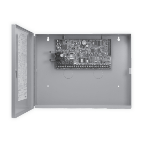
INTRODUCTION Panel Features Description The DMP XR500 Series panel is a versatile 12 Vdc, combined access control, burglary, and fire communicator panel with battery backup. The XR500 Series provides eight on-board burglary zones and two on-board 12 Vdc Class B powered zones. -
Page 11: System Components
INTRODUCTION System Components Description The DMP XR500 Series system is made up of an alarm panel with a built-in communicator, an enclosure, battery, one 16.5 VAC transformer, and keypads. You can use up to sixteen supervised 32-character LCD keypads; network communications and expansion interface cards;... -
Page 12: Lightning Protection
INTRODUCTION Lightning Protection Metal Oxide Varistors and Transient Voltage Suppressors help protect against voltage surges on XR500 Series input and output circuits. Additional surge protection is available by installing the DMP 370 or 370RJ Lightning Suppressors. Accessory Devices Interface Adaptor and Interface Cards 461 Interface Adaptor Card Allows you to connect two or more expansion interface cards to the XR500 Series panel. -
Page 13: Accessory Devices (Continued)
INTRODUCTION Accessory Devices (continued) DMP Two-Way Wireless Devices (continued) 1131 Recessed Contact* Provides a recessed contact option for door or window applications. 1135 Wireless Siren* Provides a wireless siren. 1137 Wireless LED Emergency Provides path lighting in the event of an alarm or trouble such as Burglary Alarm Output Light or can be activated simultaneously by the panel via the Trip with Panel Bell feature. -
Page 14: Accessory Devices (Continued)
INTRODUCTION Installation Mounting the Enclosure The metal enclosure for the XR500 Series must be mounted in a secure, dry place to protect the panel from damage due to tampering or the elements. It is not necessary to remove the XR500 Series PCB when installing the enclosure. Figure 2 shows the mounting hole locations for the Model 350/350A Enclosures. - Page 15 INSTALLATION PEMs for optional battery bracket Lid Mounting Holes (4 places) Lid Mounting Holes (4 places) XR500 Series Panel Phone Line Tamper Link LED Activity LED Ethernet Power RS-232 LX-Bus Output 1 Output 2 Battery Start Reset PROG Outputs 3-6 –B BELL GND RED YEL GRN BLK...
-
Page 16: Mounting Keypads And Zone Expansion Modules
INSTALLATION Mounting Keypads and Zone Expansion Modules DMP LCD keypads have removable covers that allow you to easily mount the keypad to a wall or other flat surface using the screw holes on each corner of the base. Before mounting the base, connect the keypad wire harness leads to the keypad cable from the panel and to any device wiring run to that location. -
Page 17: Primary Power Supply
INSTALLATION Primary Power Supply AC Terminals 1 and 2 Connect the transformer wires to terminals 1 and 2 on the panel. Use no more than 70 ft. of 16 gauge or 40 ft. of 18 gauge wire between the transformer and the XR500 Series. Always ground the panel before applying power to any devices: The XR500 Series must be properly grounded before connecting any devices or applying power to the panel. -
Page 18: Battery Replacement Period
INSTALLATION Battery Replacement Period DMP recommends replacing the battery every 3 to 5 years under normal use. Discharge/Recharge The XR500 Series battery charging circuit float charges at 13.9 Vdc at a maximum current of 1.0 Amps using a 50 VA or 56 VA transformer. Listed below are the various battery voltage level conditions: Battery Trouble: Below 11.9 Vdc Battery Cutoff:... -
Page 19: Xr500 Series Power Requirements
INSTALLATION XR500 Series Power Requirements During AC power failure, the XR500 Series panel and all connected auxiliary devices draw their power from the battery. All devices must be taken into consideration when calculating the battery standby capacity. The following table lists the XR500 Series panel power requirements. - Page 20 INSTALLATION Standby Battery Power Calculations Standby Current Alarm Current 736P POPIT Interface Module Qty_______ 25mA ______ Qty ______ 25mA ______ Radionics Popex, POPITs, OctoPOPITs Qty ______ ___mA ______ Qty ______ ___mA ______ 738A Ademco Wireless Interface Module Qty ______ x 75mA ______ Qty ______ x 75mA ______...
-
Page 21: Standby Battery Selection
INSTALLATION Standby Battery Selection To choose the type and number of batteries needed for 24, 60, or 72 hours of standby power based on the Amp Hours Required calculation from section 6.8 XR500 Series Power Requirements, perform the following: 1. Select the desired standby hours required from the table below: 24, 60, or 72 hours 2. -
Page 22: Bell Output
INSTALLATION Bell Output Terminals 5 and 6 Terminal 5 supplies positive 12 Vdc to power alarm bells or horns. This output can be steady, pulsed, or temporal depending upon the Bell Action specified in Bell Options. Terminal 6 is the ground reference for the bell circuit. This supervised output detects 1k Ohms or less as normal. -
Page 23: Protection Zones
INSTALLATION Protection Zones 10.1 Terminals 13–24 Zones 1 to 8 (terminals 13 to 24) on the XR500 Series panel are all grounded burglary zones. For programming purposes, the zone numbers are 1 through 8. Listed below are terminal 13 to 24 connection functions. Terminal Function Terminal... -
Page 24: Compatible 2-Wire Smoke Detector Chart
INSTALLATION 11.2 Compatible 2-Wire Smoke Detector Chart Manufacturer Model Detector Base Base # of Zone Panel Voltage Detectors Expansion Zones Range (12V/24V) Modules SLR-835B-2 715, 715-8, Hochiki HD-6 8-35 9 & 10 SLR-835BH-2 715-16 521B, 521BXT, 715, 715-8, S09A 6.5-20 9 &... -
Page 25: Description
INSTALLATION Dry Contact Relay Outputs 12.1 Description The XR500 Series panel provides two programmable auxiliary SPDT relays when equipped with two DMP Model 305 relays in sockets K6 (Output 1) and K7 (Output 2) and a Model 431 Output Harness on the J2 6-pin Header. Each relay provides one SPDT set of contacts that can be operated by any of the functions listed below: 1) Activation by zone condition: Steady, Pulsing, Momentary, and Follow 2) Activation by 24-hour 7-day schedule: One on and one off time a day for each relay... -
Page 26: Description
INSTALLATION J23 6-Pin Header 14.1 Description The XR500 Series panel supports RS-232, LX-Bus, and DMP Wireless operation. Only one operation can function at a time. Install a jumper on one pair of J23 headers to indicate how the panel is programmed to operate. Refer to the table below when installing a jumper on J23. -
Page 27: Lx-Bus Interface Cards
INSTALLATION 15.3 LX-Bus Interface Cards You can add one Interface Card (Model 481, 462N, 462P, 463C, 464-263C or 464-263H) to the XR500 Series using J6 Interface Card Connector located on the board right edge. To add more than one Interface Card install a 461 Interface Adaptor Card using J6 Interface Card Connector on the board right edge. -
Page 28: Serial Connector Leds
INSTALLATION 16.3 Serial Connector LEDs The two LEDs, located near the bottom-right corner of J21 indicate data transmission and receipt. The top LED flashes green to indicate the panel is transmitting serial data. The bottom LED flashes yellow to indicate the panel is receiving serial data. -
Page 29: Fcc Registration
INSTALLATION 18.5 FCC Registration The Model XR500 Series complies with Part 68 of the FCC rules and the requirements adopted by the ACTA. On the outside of the enclosure of this equipment is a label that contains, among other information, a product identifier in the format US:CCKAL00BXR500. -
Page 30: J16 Reset Header
INSTALLATION Reset and Tamper Headers 19.1 J16 Reset Header The reset header is located just above the terminal strip on the right side of the circuit board and is used to reset the XR500 Series microprocessor. To reset the panel when first installing the system, install the reset jumper before applying power to the panel. -
Page 31: Introduction
COMPLIANCE Listed Compliance Specifications 20.1 Introduction For applications that must conform to a local authorities installation standard or a National Recognized Testing Laboratory certificated system, please see the following sections. Universal Burglary Specifications 21.1 Introduction The programming and installation specifications contained in this section must be completed when installing the XR500 Series panel in accordance with any of the burglary standards. -
Page 32: Ownership
COMPLIANCE Area Information 22.1 Ownership The control unit system shall be under one ownership. 22.2 Annunciation The System shall be installed so that when arming any area from any keypad, the local bell shall annunciate. 22.3 Trouble Display The Status List programming shall be set to annunciate all trouble messages at all keypads. 22.4 Closing Wait The Closing Wait option must be programmed YES. -
Page 33: Ansi/Ul 1610 And Ansi/Ul
COMPLIANCE Central-Station and Proprietary Burglar-Alarm Units ANSI/UL 1610 AND ANSI/UL 1076 24.1 Opening/Closing Reports The Opening/Closing Reports option must be programmed as YES. 24.2 Closing Wait The Closing Wait option must be programmed YES. 24.3 Entry Delay The maximum entry delay used must not be more than 60 seconds when using Model 350A or 350H Attack Resistant Housing. -
Page 34: Net With Cell As Alternate Primary And Dialer Backup Standard Or Encrypted Line Security
COMPLIANCE 24.11 NET with CELL as Alternate Primary and Dialer Backup, Standard or Encrypted Line Security Standard or Encrypted Line Security is provided using NET communication with Model 463C, 464-263C or 464-263H for CELL as an alternate primary and with digital dialer as a backup. XR500 network communication is used as primary with a 6 minute check-in when armed, and a random check-in over a 60 minute period when disarmed. -
Page 35: Holdup Alarm Units Ansi/Ul
COMPLIANCE Holdup Alarm Units ANSI/UL 636 25.1 ANSI/UL 1610 Required The programming and installation specifications contained in this section must be completed in addition to ANSI/UL 1610 Specifications when installing a Model 1142 with a Model XR500 Series panel. 25.2 1100X/1100XH Wireless Receiver The Model 1100X/1100XH Wireless Receiver in conjunction with the Model 1142 Holdup Alarm Transmitter must be installed in the system. -
Page 36: Bell
COMPLIANCE 27.4 Bell A local audible signal appliance must be used such as Ademco AB12M bell and bell housing. The alarm housing for a mercantile alarm system without a remote alarm transmission connection shall be mounted on the outside of the building, visible from a public street or highway. It shall be accessible for examination and repair. -
Page 37: Model 463C, Net With Cell As Alternate Primary And Dialer Backup, Standard Or Encrypted Line Security
COMPLIANCE 27.10 Model 463C, NET with CELL as Alternate Primary and Dialer Backup, Standard or Encrypted Line Security Standard or Encrypted Line Security is provided using NET communication with CELL as an alternate primary and with digital dialer as a backup. XR500 network communication is used as primary with a 6 minute check-in when armed, and a random check-in over a 60 minute period when disarmed. -
Page 38: Mercantile
COMPLIANCE Police Station Connected and Local Burglar Alarm Units ANSI/UL 609 28.1 Mercantile For Mercantile and Police Station Connect operation the Model XR500 Series must be mounted in an Attack Resistant Housing, (DMP Model 350A or 350H). 28.2 Entry Delay The maximum entry delay used must not be more than 60 seconds when using the Model 350A or 350H housing. -
Page 39: Access Control System Units Ansi/Ul
COMPLIANCE Access Control System Units ANSI/UL 294 29.1 Panel Designation The XR500 Series panels are designated stand alone units. 29.2 Tamper Protection For listed Access Control installations, a tamper switch must be used. 29.3 Transformer The total combined Auxiliary and Bell outputs cannot exceed 1.3 Amps with a 50 VA Transformer. The total combined Auxiliary and Bell outputs cannot exceed 1.9 Amps with a 56 VA Transformer. -
Page 40: Police Station Phone Number
COMPLIANCE 30.7 Police Station Phone Number The digital dialer telephone number programmed for communication must not be a police station phone number, unless that phone number is specifically provided for that purpose. 30.8 System Maintenance To ensure continuous satisfactory operation of any alarm system, proper installation and regular maintenance by the installing alarm company and frequent testing by the end user is essential. -
Page 41: Power Supply
COMPLIANCE Control Units for Fire-Protective Signaling Systems ANSI/UL 864, NFPA 72 31.1 Power Supply For listed Commercial Fire installations, the 50 VA Plug-in transformer cannot be used. The total combined current from Terminals 7, 11, 25, and 27 cannot exceed 1.2 Amps. 31.2 Zone Restoral Reports The Restoral Reports option must be selected as YES or Disarm. -
Page 42: Remote Station Protective Signaling Systems
COMPLIANCE 31.7 Remote Station Protective Signaling Systems You must provide 60 hours of standby battery. See section 6.9 in this guide for standby battery calculations. Two Radionics Model D127 Reversing Relay Modules provide two reversing polarity telephone connections. See the D127 Installation Instruction sheet for wiring details. -
Page 43: Notification Appliances
COMPLIANCE 31.11 Notification Appliances The following table indicates the approved notification appliances that can be used with the XR500 Series system. Wheelock Model No. Description Max No. of Appliances using 56 VA/100 VA MT-12/24 Multi-tone Horn MB-G6-12 Bell, 6 inch MB-G10-12 Bell, 10 inch ST Series... -
Page 44: Introduction
COMPLIANCE New York City (FDNY) Specifications 34.1 Introduction The programming specifications contained in section 34.2 or 34.3 must be completed when installing the XR500 Series panel for New York City (FDNY) fire alarm installations for IP communication applications. Refer to the FDNY Certificate of Approval #6123 or #6145 for the complete conditions of approval. -
Page 45: Shipping Defaults And Recommended Programming For Ansi/Sia Cp-01-2010
COMPLIANCE False Alarm Reduction Programmable Options * 35.1 Shipping Defaults and Recommended Programming for ANSI/SIA CP-01-2010 DMP XR500 SIA CP-01 FEATURE PROGRAMMING SHIPPING RECOMMENDED PARAGRAPH # AND REQUIREMENT RANGE GUIDE LT-0679 DEFAULT PROGRAMMING* DESCRIPTION SECTION # Required 4.2.2.1 Exit Time 15.2 Exit Delay 45 sec. -
Page 46: Call Waiting
WIRING DIAGRAMS False Alarm Reduction Programmable Options (continued) 35.2 Call Waiting The Call Waiting default setting is disabled. To cancel the Call Waiting feature, program * (star) 7 0 P (pause), the standard telephone code prefix that cancels call waiting, into the telephone number string. Cancel Call Waiting for telephone lines that have Call Waiting operational on the telephone line. -
Page 47: With Nac Extender
WIRING DIAGRAMS Wiring Diagrams 36.1 866 with NAC Extender To panel zone To panel alarm output To panel terminal 7 To panel zone To panel terminal 10 Normal/Silence Switch Model 310 Model 310 1K EOL 1K EOL 1 AUX PWR 2 GND 3 Alarm In 4 Bell PWR In... -
Page 48: Class B Style W Using Single Notification Appliance
WIRING DIAGRAMS 36.2 866 Class B Style W using Single Notification Appliance J6 Interface Tamper Phone Line Card Expansion XR500 Series Command Connector Processor™ Panel Ethernet 75VA 50VA Power LED RS-232 LX-Bus Output 2 Output 1 Buzzer Battery Start PROG BELL GND RED YEL GRN BLK... -
Page 49: Class B Style W Multiple Notification Appliance Circuit
WIRING DIAGRAMS 36.3 866 Class B Style W Multiple Notification Appliance Circuit J6 Interface Card Expansion Tamper Phone Line Connector XR500 Series Command Processor™ Panel Ethernet 75VA 50VA Power LED RS-232 LX-Bus Output 2 Output 1 Buzzer Battery Start PROG BELL GND RED YEL GRN BLK... -
Page 50: Class B Style W Dual Notification Appliance Circuits
WIRING DIAGRAMS 36.4 866 Class B Style W Dual Notification Appliance Circuits J6 Interface Card Expansion Tamper Connector Phone Line XR500 Series Command Processor™ Panel Ethernet 75VA 50VA Power LED RS-232 LX-Bus Output 2 Output 1 Buzzer Battery Start PROG BELL GND RED YEL GRN BLK... -
Page 51: Class B Style W Using Single Notification Appliance
WIRING DIAGRAMS 36.5 865 Class B Style W using Single Notification Appliance J6 Interface Card Expansion Tamper Connector Phone Line XR500 Series Command Processor™ Panel Ethernet 75VA 50VA Power LED RS-232 LX-Bus Output 2 Output 1 Buzzer Battery Start PROG BELL GND RED YEL GRN BLK... -
Page 52: Class B Style W Multiple Notification Appliance Circuit
WIRING DIAGRAMS 36.6 865 Class B Style W Multiple Notification Appliance Circuit J6 Interface Card Expansion Tamper Connector Phone Line XR500 Series Command Processor™ Panel Ethernet 75VA 50VA Power LED RS-232 LX-Bus Output 2 Output 1 Buzzer Battery Start PROG BELL GND RED YEL GRN BLK... -
Page 53: Class B Style W Dual Notification Appliance Circuits
WIRING DIAGRAMS 36.7 865 Class B Style W Dual Notification Appliance Circuits J6 Interface Card Expansion Tamper Connector Phone Line XR500 Series Command Processor™ Panel Ethernet 75VA 50VA Power LED RS-232 LX-Bus Output 2 Output 1 Buzzer Battery Start PROG BELL GND RED YEL GRN BLK... -
Page 54: 865 Class A Style X Using Single Notification Appliance
WIRING DIAGRAMS 36.8 865 Class A Style X using Single Notification Appliance J6 Interface Card Expansion Tamper Connector Phone Line XR500 Series Command Processor™ Panel Ethernet 75VA 50VA Power LED RS-232 LX-Bus Output 2 Output 1 Buzzer Battery Start PROG BELL GND RED YEL GRN BLK... -
Page 55: 867 Class B Style W Using Single Notification Appliance
WIRING DIAGRAMS 36.9 867 Class B Style W using Single Notification Appliance J6 Interface Card Expansion Connector Tamper Phone Line XR500 Series Command Processor™ Panel Ethernet 75VA 50VA Power LED RS-232 LX-Bus Output 2 Output 1 Buzzer Battery Start PROG BELL GND RED YEL GRN BLK... -
Page 56: 867 Class B Style W Multiple Notification Appliance Circuit
WIRING DIAGRAMS 36.10 867 Class B Style W Multiple Notification Appliance Circuit J6 Interface Card Expansion Connector Tamper Phone Line XR500 Series Command Processor™ Panel Ethernet 75VA 50VA Power LED RS-232 LX-Bus Output 2 Output 1 Buzzer Battery Start PROG BELL GND RED YEL GRN BLK... -
Page 57: 867 Class B Style W Multiple Notification Appliance Circuits
WIRING DIAGRAMS 36.11 867 Class B Style W Multiple Notification Appliance Circuits J6 Interface Card Expansion Connector Tamper Phone Line XR500 Series Command Processor™ Panel Ethernet 75VA 50VA Power LED RS-232 LX-Bus Output 2 Output 1 Buzzer Battery Start PROG BELL GND RED YEL GRN BLK... -
Page 58: Panel Slave Communicator For Facp Using 630F Annunciator
WIRING DIAGRAMS 36.12 Panel Slave Communicator for FACP using 630F Annunciator XR100/XR500 Series Command Processor™ Panel Slave Communicator for FACP Tamper Phone Line using 630F Annunciator for local annunciation for slave Ethernet Power LED RS-232 LX-Bus Output 2 Output 1 Battery Start PROG... -
Page 59: Panel Slave Communicator For Facp Using Outputs
WIRING DIAGRAMS 36.13 Panel Slave Communicator for FACP using Outputs XR500 Series Command Processor™ Panel Tamper Phone Line Communication Fail Output 1 must be programmed as a Comm Fail output in Output Ethernet Options. 75VA 50VA Fire Trouble Power LED RS-232 Output 2 must be programmed as a Fire Trouble output in... -
Page 60: Dual Style D Zone Module Installation
WIRING DIAGRAMS 36.14 Dual Style D Zone Module Installation Tamper Interface XR500 Series Card Expansion Command Processor™ Connector Panel 75VA 50VA RS-232 Battery Start Reset –B BELL GND RED YEL GRN BLK SMK GND Z2 Z3 Z4 Z5 Z6 Z7 Z8 Z9+ Z9–... -
Page 61: Derived Channel Installation Using Bosch D8122
WIRING DIAGRAMS 36.15 Derived Channel Installation Using Bosch D8122 XR500 Series Command Processor™ Panel Form C Dry Contact Relays (J2) Tamper Phone Line Output Color Code–Model 431 Harness Interface Output 2 N/O Orange/White Card Expansion Output 2 Com White/Gray Connector Output 2 N/C Violet/White Output 1 N/O Orange Output 1 Com Gray... -
Page 62: Rothenbuhler 5110 High Security Bell Wiring
WIRING DIAGRAMS 36.16 Rothenbuhler 5110 High Security Bell Wiring Digital Monitoring Products XR500 Series Installation Guide... -
Page 63: Lx-Bus™ Module Connection
WIRING DIAGRAMS 36.17 LX-Bus™ Module Connection LX-Bus Expansion Interface Card DMP Models 481, 462N, 462P, or 464-263H. Each LX-Bus Module must have its own independent address ranging from 00 to 99. A Supervisory zone must be programmed into the XR500 Series to properly supervise each module. -
Page 64: Model 860 Relay Module Connection
WIRING DIAGRAMS 36.18 Model 860 Relay Module Connection XR500 Series Tamper Command Processor™ Panel Interface Card Expansion Connector J2 Output Header All outputs must be located 75VA within the same room as 50VA the control panel. Model 860 RS-232 Relay Module BL K Relay 1 Common... -
Page 65: System Sensor 2-Wire Smoke Detectors
WIRING DIAGRAMS 36.20 System Sensor 2-Wire Smoke Detectors Tamper Interface Phone Line Card XR500 Series Panel Expansion Connector Link LED Power LED Ethernet Power RS-232 LX-Bus Output 1 Output 2 Battery Start Reset PROG Outputs 3-6 –B BELL GND RED YEL GRN BLK SMK GND Z2 Z3 Z4 Z5... -
Page 66: System Sensor I4 Series Smoke And Co Detectors Using A Single Cosmod2W Module
WIRING DIAGRAMS 36.21 System Sensor i4 Series Smoke and CO Detectors Using A Single COSMOD2W Module See i4 Series Interface Module Installation and Maintenance Instructions for additional information. COSMOD2W To Panel SMK or Optional Power Supply To GND from Panel or Power Supply Program Smoke zone To Panel or Zone Expander Power In +... -
Page 67: System Sensor I4 Series Smoke And Co Detectors Using Multiple Cosmod2W Modules
WIRING DIAGRAMS 36.22 System Sensor i4 Series Smoke and CO Detectors Using Multiple COSMOD2W Modules See i4 Series Interface Module Installation and Maintenance Instructions for additional information. N/O to CO Trigger Common N/O to Bell In Common COSMOD2W To Panel power SMK terminal or Optional Power Supply Power In + Power In -... -
Page 68: Revisions To This Document
REVISIONS Revisions to This Document This section explains the changes that were made to this document during this revision. This section lists the version, section number with heading, and a quick summary of the change. Version Section Number and Heading Summary of Changes 1.29 11.2 Compatible 2-Wire Smoke... - Page 69 Digital Monitoring Products XR500 Series Installation Guide...
- Page 70 Certifications Export Control California State Fire Marshal (CSFM) The XR500E uses AES encryption and any export beyond the United States must be in accordance with Export ANSI/SIA CP-01-2010 False Alarm Reduction Administration Regulations. FCC Part 15 FCC Part 68 Registration ID CCKAL00BXR500 NIST Validated XR500E Encrypted Command Processor Panel Certificate #130 New York City (FDNY COA #6167)
Need help?
Do you have a question about the XR500N SERIES and is the answer not in the manual?
Questions and answers