Table of Contents
Advertisement
Advertisement
Table of Contents

Related Manuals for Magnum Energy ME-AGS-S


Summary of Contents for Magnum Energy ME-AGS-S
- Page 1 ME-AGS-S Automatic Generator Start For Standalone Systems Owner’s Manual...
- Page 2 If the ME-AGS-S fails, it is reasonable to assume that the health of the user or other persons may be endangered.
-
Page 3: Table Of Contents
2.4 Connecting the Communication Cable ..........8 2.5 ME-AGS-S Terminal Block Wiring ........... 9 2.6 Warning Label ................13 2.7 Common ME-AGS-S Generator Wiring Diagrams ......13 3.0 Setup ..................17 3.1 Internal Settings ............... 17 3.2 External Settings ..............19 3.3 AGS Functional Tests .............. -
Page 4: Introduction
Info: This manual is for the ME-AGS-S with revision 5.0 or higher; see Figure 3-1 on page 17 for information on where to locate your revision level. -
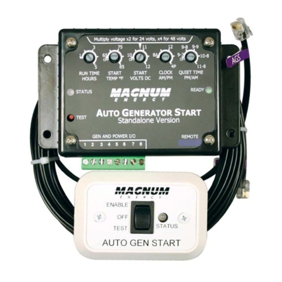
Page 5: Me-Ags-S Components/Features
1.0 Introduction 1.1 ME-AGS-S Components/Features The ME-AGS-S is equipped with the following components and features: • AGS Remote Switch • Communications Cable • AGS-S Controller 1.1.1 AGS Remote Switch The AGS Remote Switch is the user interface display and connects to the AGS controller thru the communications cable. -
Page 6: Figure 1-3, Me-Ags-S Controller Features
READY Indicator - this green LED indicator illuminates to indicate that the AGS is powered and the remote switch is connected. REMOTE Connection Port (purple label) - a RJ12 port which provides the connection point for the remote switch. Figure 1-3, ME-AGS-S Controller Features © 2010 Magnum Energy, Inc. -
Page 7: Installation
2.0 Installation 2.0 Installation Installing the ME-AGS-S is a simple process. Before installing, read this entire section to be aware of all aspects of the installation; then, you can thoroughly plan the details to ensure the overall system requirements are accomplished. -
Page 8: Figure 2-1, Me-Ags-S System Diagram
G enerator run s ignal C om m on battery negativ es (M onitored battery and G enerator s tarting battery ) M onitored B attery B ank A uto- S tart G enerator Figure 2-1, ME-AGS-S System Diagram © 2010 Magnum Energy, Inc. -
Page 9: Required Components And Tools
• 25 ft communications cable 2.2.2 List of other required equipment and materials: • 16 to 12 AWG wire for connecting the ME-AGS-S to the generator start/ stop circuit and to the battery bank • In-line fuse holders (with 5-amp DC fuse) 2.2.3 Tools that may be required to install the ME-AGS-S:... -
Page 10: Figure 2-2, Controller Dimensions
1 /8 side side " 7 /16 " 1 /4 cutout Remote " " 5/16 3/16 Bezel bezel " 5 /8 7 /6 4 " drill " Remote face -plate face-plate " Figure 2-3, Remote Dimensions © 2010 Magnum Energy, Inc. -
Page 11: Connecting The Communication Cable
Figure 2-5. b lu e same colors T A B from top to bottom (tabs facing toward you) w h ite T A B Figure 2-5, Communication Cable (Data Type) © 2010 Magnum Energy, Inc. -
Page 12: Me-Ags-S Terminal Block Wiring
2.0 Installation 2.5 ME-AGS-S Terminal Block Wiring The controller should now be mounted. For the following steps; refer to Figure 2- 7 for reference when wiring the generator to the controllers terminal block: 1. Unplug the green 8-port friction-fi t terminal block from the controller by pulling it straight out. -
Page 13: Figure 2-6, Generator Run Sense Options
Inside Generator On Generator 120VAC Outlet Generator Battery D C F us e (5A m ax ) 1 2 0V A C C o il R e la y Figure 2-6, Generator Run Sense Options © 2010 Magnum Energy, Inc. - Page 14 Terminal #7: This is the Normally Open (N.O.) position of Relay 2 (RY2). • Relay 3 (RY3) Terminal #1: This is the Normally Open (N.O.) position of Relay 3 (RY3). Terminal #8: This is the Common (COM) position of Relay 3 (RY3). © 2010 Magnum Energy, Inc.
-
Page 15: Figure 2-7, Wiring To The Ags Controller Terminal Block
C o m m o n (C O M ) co n ta ct o n R e la y 3 (R Y 3 ) Figure 2-7, Wiring to the AGS Controller Terminal Block © 2010 Magnum Energy, Inc. -
Page 16: Warning Label
PN : 62 -0002 R ev A Figure 2-8, Warning Label 2.7 Common ME-AGS-S Generator Wiring Diagrams The most common generator starting/run/stop circuits can be divided into three major types - Two-wire, Three-wire “momentary”, or Three-wire “main- tain”. The following generator wiring diagrams are provided to give examples of these generator types. -
Page 17: Figure 2-9, Two-Wire Start Type Generators
To ta l S ta rt a tte m p ts R e la y tim in g fo r G e n T yp e : 2 -W ire M a in ta in M o d e Figure 2-9, Two-wire Start Type Generators © 2010 Magnum Energy, Inc. -
Page 18: Figure 2-10, Three-Wire Momentary Type Generators
S ta rt D e la y Tim e 1 4 se c. R e la y tim in g fo r G e n T yp e : 5 -w ire M o d e Figure 2-10, Three-wire Momentary Type Generators © 2010 Magnum Energy, Inc. -
Page 19: Figure 2-11, Three-Wire Maintain Type Generators
D e la y tim e 2 se c. R e la y tim in g fo r G e n T yp e : P o rta b le M o d e Figure 2-11, Three-wire Maintain Type Generators © 2010 Magnum Energy, Inc. -
Page 20: Setup
Table 3-1 to determine and set the correct GEN TYPE setting for your generator’s start/stop requirements. For examples and assistance in viewing which GEN TYPE setting is used for specific generators, view the ‘ Generator Wiring Diagrams’ under the Service and Support area at www.magnumenergy.com. © 2010 Magnum Energy, Inc. -
Page 21: Table 3-1, Gen Type Settings
G ener ator s : BT D A / BEG (W es ter bek e ) , 205 -D S (M ar tin D ies el ) , N L- M o d e 673 (N or ther n Lights ) © 2010 Magnum Energy, Inc. -
Page 22: External Settings
Table 3-2 are appropriate. If you need to make changes to the factory settings, you can do so by rotating the knobs either clockwise or counterclockwise on the front panel of the AGS Controller; see Figure 3-3. Table 3-2, ME-AGS-S Default Settings Adjustable Settings Factory Default Values... - Page 23 Info: If the generator is running when the Quiet Time evening hour (PM) is reached, it will automatically stop and will not be able to automatically start until after the Quiet Time morning hour (AM) has passed. © 2010 Magnum Energy, Inc.
-
Page 24: Ags Functional Tests
4 attempts the generator fails to start, the status LED will turn red indicating a fault. Note: Only one start attempt is provided when the GEN TYPE setting is in the 2-Wire Standby Mode position. © 2010 Magnum Energy, Inc. -
Page 25: Operation
This means the remote switch is either not connected, incorrectly connected, is defective, or has an incorrect or defective cable. STATUS Indicator (green/red) READY Indicator (green) TEST Switch Figure 4-1, Controller Front Panel Controls and Indicators © 2010 Magnum Energy, Inc. -
Page 26: Remote Switch Operation
Solid Red: This is a fault condition to indicate that the generator has not provided a correct Run Sense voltage to terminals 2 (+) and 4 (-) of the AGS controller after four start attempts. Control STATUS Switch Indicator Figure 4-2, Remote Switch Front Panel Controls and Indicators © 2010 Magnum Energy, Inc. -
Page 27: Ags System Operation
AGS controller falls to the START VOLTS DC. There is no delay if the AGS attempts to start the generator when the temperature around the Remote Switch rises to the START TEMP °F setting. © 2010 Magnum Energy, Inc. -
Page 28: Troubleshooting
2. Try a different 6-conductor tele- phone cable (see Figure 2-5). Switch OFF, then ENABLE to reset. READY is ON The remote control No problem - normal operation. (solid) = Power switch is connected connected to the REMOTE port. © 2010 Magnum Energy, Inc. -
Page 29: Limited Warranty
Magnum Energy shall not be liable for any other losses or damages. Upon request from Magnum Energy, the original purchaser must prove the product’s original date of purchase by a dated bill of sale, itemized... -
Page 30: How To Receive Repair Service
6.0 Warranty and Service 6.1 How to Receive Repair Service If your Product requires warranty service or repair, contact either: 1. An Authorized Service Center, which are listed on the Magnum Energy Website at http://www.magnumenergy.com/ServiceCenters.htm, or Magnum Energy, Inc. at:... -
Page 31: Appendix
Appendix Appendix Optional Accessories for the ME-AGS-S The following two Pigtail Adapters are available from Magnum Energy for use with the ME-AGS-S. They are useful in applications where there is a requirement to conveniently and automatically turn the generator on/off... - Page 32 Magnum Energy, Inc. 2211 West Casino Rd. Everett, WA 98204 Phone: 425-353-8833 Fax: 425-353-8390 Web: www.magnumenergy.com PN: 64-0004 Rev A...
Need help?
Do you have a question about the ME-AGS-S and is the answer not in the manual?
Questions and answers