Table of Contents
Advertisement
Advertisement
Table of Contents
Troubleshooting

Related Manuals for Magnum MS2000


Summary of Contents for Magnum MS2000
- Page 1 MS Series Pure Sine Wave Inverter/Charger Owner’s Manual...
-
Page 2: Contact Information
We understand that you have many purchasing options in the marketplace, and we are pleased that you have decided on this Magnum Energy product. This MS Series inverter/charger was proudly assembled and tested in the United States at our facility in Everett, Washington. -
Page 3: Safety Information
Safety Information IMPORTANT SAFETY INSTRUCTIONS SAVE THESE INSTRUCTIONS THIS MANUAL CONTAINS IMPORTANT INSTRUCTIONS FOR THE MS SERIES INVERTER/CHARGER THAT SHALL BE FOLLOWED DURING THE INSTALLATION AND OPERATION OF THIS PRODUCT. Before using the MS Series, read all instructions and cautionary markings. Also, be sure to review the individual manuals provided for each component of the system. -
Page 4: Battery Safety
Safety Information • Overcurrent protection for the AC output wiring is not provided as an integral part of this inverter. Overcurrent protection of the AC output wiring must be provided as part of the system installation. Refer to Section 2.5 “AC Wiring” for more information. •... - Page 5 Safety Information CONSIGNES DE SÉCURITÉ IMPORTANTES CONSERVER CES INSTRUCTIONS CE MANUEL CONTIENT DE IMPORTANTES POUR LA SÉRIE MS ONDULEUR/CHARGEUR QUI DOIVENT ETRE SUIVIES PENDANT L’INSTALLATION ET FONCTIONNEMENT DE CE PRODUIT. Avant d’utiliser la série MS, lire toutes les instructions etles mises en garde. Aussi, n’oubliez pas depasser en revue les différents manuels fournispour chaque composant du système.
- Page 6 Safety Information • Protection contre les surintensités pour le câblage de sortie AC n’est pas fourni en tant que partie intégrante de cet onduleur. Protection contre les surintensités du câblage de sortie CA doit être fournie dans le cadre de l’installation du système. Reportez-vous à la Section 2.5 Câblage ca dans le chapitre d’installation pour plus d’informations.
-
Page 7: Table Of Contents
2.5.6 AC Wiring Confi gurations (MS2012, MS2812, MS2024, MS4024, & MS4048) ..25 2.5.7 AC Conductor Wiring (MS2000 models) ............31 2.5.8 AC Wiring Confi guration (MS2000 models) ............32 Grounding Inverters ..................35 2.6.1 Sizing the Grounding Electrode Conductors .............36 2.6.2 System Bonding Jumper ................38 2.6.3... - Page 8 Table of Contents (Cont.) Operation ..................... 45 Inverter Mode ....................45 Standby Mode ....................47 Battery Charging ...................48 Transfer Time ....................50 Battery Temperature Sensor Operation .............50 Protection Circuitry Operation ................51 Inverter Startup ....................52 Factory Default Values ..................53 Inverter Fan Operation ...................54 3.10 Using a Remote with the MS Series Inverter ............54 Maintenance and Troubleshooting ............
- Page 9 Figure 1-4, Left Side Features (MS2000 Series) ..............6 Figure 2-1, Simplifi ed Installation for Permanent Installations (MS Series) ......8 Figure 2-2, Simplifi ed Installation for Permanent Installations (MS2000) ....... 9 Figure 2-3, Approved Mounting Positions ................ 11 Figure 2-4, MS Dimensions (MS2012, MS2812, MS2024, MS4024, MS4048) ......12 Figure 2-5, MS Dimensions (MS2000) ................
- Page 10 Table 2-2, DC Wire Size For Increased Distance ..............18 Table 2-3, AC Input/Output Wiring Confi gurations .............25 Table 2-4, AC Input/Output Wiring Confi gurations (MS2000 models)........32 Table 2-5, AC Grounding Electrode Conductor Sizing ............36 Table 2-6, Equipment Grounding Conductor Sizing ............38 Table 3-1, Inverter Battery Turn On/Off Levels ..............51...
-
Page 11: Introduction
The MS Series also meets the KKK-A-1822E standard for use in ambulances. Note¹ – The MS2000 models are not listed to the UL 1741 standard. Page 1 © 2016 Sensata Technologies... -
Page 12: How An Inverter/Charger Works
Introduction How an Inverter/Charger Works There are two modes of operation associated with this inverter/charger: Inverter Mode When the inverter is properly connected to batteries and turned on, the direct current (DC) from the batteries is transformed into a pure sine wave alternating current (AC). This AC is similar to the voltage provided by your utility and is used to power any electrical appliances (i.e., AC loads) connected to the inverter’s output. -
Page 13: Features And Benefi Ts
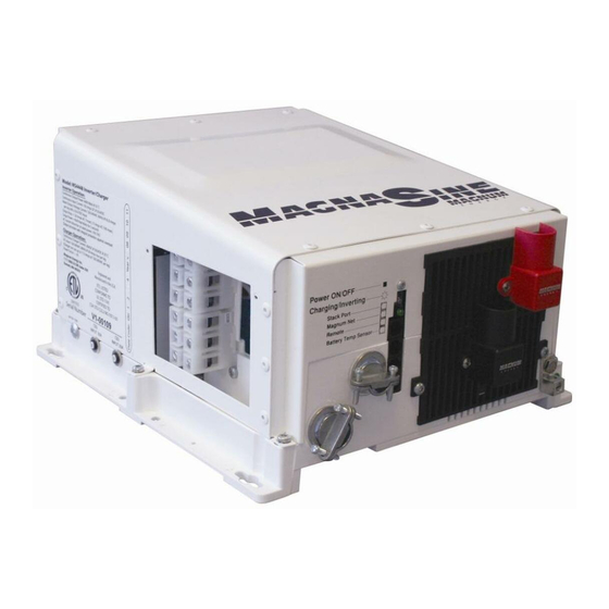
Note: While not pictured, the MS2000 models have the same features as those listed in this section. The MS inverter is equipped with the following features (refer to Figures 1-1 and 1-2): Power ON/OFF Switch –... -
Page 14: Figure 1-2, Electrical Connection Points
Introduction DC Equipment Ground Terminal – this connection is used to tie the exposed chassis of the inverter to the DC grounding system. This terminal accepts CU/AL conductors from #14 to #2 AWG (2.1 to 33.6 mm2). Tightening torque is 45 in-lb. AC Entry/Exit Connections –... -
Page 15: Figure 1-3, Left Side Features (Ms2012, Ms2812, Ms2024, Ms4024, Ms4048)
(Figure 2-10). This terminal block is used to hardwire all inverter AC input and output wiring connections. Remove the two screws to access the AC wiring terminal block. Note: The MS2000 models do not have the AC wiring terminal block. AC Input Circuit Breaker (CB3) – this circuit breaker protects the unit’s internal charger wiring and pass-thru relay while in Standby mode. -
Page 16: Figure 1-4, Left Side Features (Ms2000 Series)
Note: The model shown is not a -15B or -20B model, therefore it does not show any AC output breakers. Models without output breakers (CB1 & CB2) use carriage bolts to fi ll the breaker openings. Figure 1-4, Left Side Features (MS2000 Series) © 2016 Sensata Technologies... -
Page 17: Installation
• MS Series Owner’s Manual If items appear to be missing or damaged, contact your authorized Magnum product dealer or Sensata. If at all possible, keep your shipping box to help protect your inverter from damage if it ever needs to be returned for service. Save your proof-of-purchase as a record of your ownership;... -
Page 18: Figure 2-1, Simplifi Ed Installation For Permanent Installations (Ms Series)
ME-ARC50 ME-RC50 Transfer FAULT SELECT Switch ON/OFF CHARGER ON/OFF INVERTER SHORE METER SETUP TECH Remote Controls (Magnum Accessories) Main Panel Sub-Panel 120VAC inverter power (or 120/240VAC pass-thru power) to sub-panel 120/240VAC power to inverter MS Series Inverter/ Charger Overcurrent Shunt... -
Page 19: Figure 2-2, Simplifi Ed Installation For Permanent Installations (Ms2000)
DC Overcurrent Protection 120VAC (breaker or fuse/switch) power to inverter ME-BMK Battery Monitor with shunt (Magnum Accessory) ME-SBC Smart Battery Combiner (Magnum Accessory) Battery Bank Figure 2-2, Simplifi ed Installation for Permanent Installations (MS2000) Page 9 © 2016 Sensata Technologies... -
Page 20: Locating The Inverter
Installation 2.1.3 Locating the Inverter Only install the inverter in a location that meets the following requirements: Clean and Dry – The inverter should not be installed in an area that allows dust, fumes, insects, or rodents to enter or block the inverter’s ventilation openings. This area also must be free from any risk of condensation, water, or any other liquid that can enter or fall on the inverter. -
Page 21: Mounting The Inverter
Installation Mounting the Inverter The inverter base can reach a temperature up to 90°C (194°F) and should be mounted on a noncombustible surface*. This surface and the mounting hardware must also be capable of supporting at least twice the weight of the inverter. To meet regulatory requirements, the MS Series must be mounted in one of the following positions as shown in Figure 2-3: •... -
Page 22: Figure 2-4, Ms Dimensions (Ms2012, Ms2812, Ms2024, Ms4024, Ms4048)
Installation Figure 2-4, MS Dimensions (MS2012, MS2812, MS2024, MS4024, MS4048) © 2016 Sensata Technologies Page 12... -
Page 23: Figure 2-5, Ms Dimensions (Ms2000)
Installation Figure 2-5, MS Dimensions (MS2000) Page 13 © 2016 Sensata Technologies... -
Page 24: Wiring The Inverter - General Requirements
Installation Wiring the Inverter – General Requirements This section describes the requirements and recommendations for wiring the MS Series inverter/ charger. Before wiring the MS Series inverter/charger, carefully read all instructions. Wiring should meet all local codes and standards and be performed by qualifi ed personnel such as a licensed electrician. -
Page 25: Dc Wiring
Installation DC Wiring This section describes the inverter’s required DC wire sizes, the recommended disconnect/ overcurrent protection, and how to make the DC connections to the inverter and the battery bank. Refer to Figure 2-6 when connecting the DC wires. WARNING: Even though DC voltage is “low voltage”, signifi... -
Page 26: Figure 2-6, Dc And Battery Temperature Sensor Wiring
Installation MS Series Inverter/Charger (front view) Inverter’s DC Negative Busbar Inverter’s DC Positive Busbar Inverter’s Equipment Ground Wire Battery Temp Sensor Cable* MMP enclosure – for single inverter installations (includes DC disconnect breaker, DC shunt for battery monitor, and inverter DC busbars). If multiple inverters will be installed, see the MP enclosures - designed to allow up to four inverters to be connected together. -
Page 27: Dc Wire Sizing
Wire Size DC Breaker Wire Size Current Fuse Size Wire Size [rating] Size [rating] #4/0 AWG #2/0 AWG 300 amps MS2000/ #6 AWG (107.2 mm (67.4 mm 267 amps 250 amps with time MS2012 (13.3 mm [260 amps] [300 amps] delay... -
Page 28: Dc Cable Connections
In Conduit In Free Air In Conduit In Free Air #4/0 AWG #2/0 AWG #4/0 AWG x2 #4/0 AWG #4/0 AWG x2 MS2000 (107.2 mm (67.4 mm (107.2 mm (107.2 mm recommended (107.2 mm #4/0 AWG #2/0 AWG #4/0 AWG x2... -
Page 29: Wiring The Battery Bank
Installation CAUTION: Battery Ensure nothing is Temperature placed between the DC split washer Sensor terminal and ring lug. CAUTION: Ensure nothing is 5/16-18 placed between Inverter DC terminal battery cable Flange or the cable ring lug 5/16–18 bolt, (with ring lug) Kep nut and battery post. -
Page 30: Battery Temperature Sensor Installation And Wiring
Installation 2.4.5 Battery Temperature Sensor Installation and Wiring The Battery Temperature Sensor (shown in Figure 2-9) provides the inverter with precise battery temperature information to automatically adjust the ABSORB and FLOAT charge voltage set-points. This allows the batteries to be correctly charged under extreme temperature changes. If the temperature sensor is NOT installed and the batteries are subjected to large temperature changes, the battery life may be shortened. -
Page 31: Wiring The Inverter To The Battery Bank
Installation 2.4.6 Wiring the Inverter to the Battery Bank CAUTION: The inverter is NOT reverse polarity protected—if this happens the inverter will be damaged and will not be covered under warranty. Before connecting the DC wires from the batteries to the inverter, verify the correct battery voltage and polarity using a voltmeter. -
Page 32: Ac Wiring
Installation AC Wiring This section provides information on how to make the AC connections to the inverter using the correct AC wire size and corresponding overcurrent protection. See Figures 2-11 through 2-17. 2.5.1 Pre-AC Wiring Requirements CAUTION: Before installing any AC wiring, review the safety information at the beginning of this manual and the following to ensure a safe and long-lived system: •... -
Page 33: Recommended Gfci (Ground Fault Circuit Interruption) Outlets
Installation 2.5.3 Recommended GFCI (Ground Fault Circuit Interruption) Outlets In compliance with UL standards, Sensata tested the following series of GFCIs and found that they function properly when connected to the inverter’s AC output: • Hubbel #GF520EMBKA • Cooper VGF15W •... -
Page 34: Ac Conductor Wiring (Ms2012, Ms2812, Ms2024, Ms4024, & Ms4048)
The following steps are basic guidelines for installing and connecting the AC wiring to and from all MS Series inverters (except MS2000 Series model inverters—for instructions on wiring MS2000 Series model inverters, refer to Section 2.5.7). Before proceeding, refer to Table 2-3 to determine your AC wiring confi... -
Page 35: Ac Wiring Confi Gurations (Ms2012, Ms2812, Ms2024, Ms4024, & Ms4048)
The following table provides the different wiring confi gurations for installing and connecting the AC conductors to and from the inverter (refer to Figures 2-11 to 2-15 for installation drawings showing these confi gurations). Refer to Table 2-4 (and Figures 2-16 & 2-17) for the MS2000 models. Table 2-3, AC Input/Output Wiring Confi gurations... -
Page 36: Figure 2-11, Ac Wiring For Single In - Single Out (30 A) Confi Gurations
Installation AC Terminal Block (AC input and output wiring) MS Series Inverter AC GROUNDS (to/from both panels) SINGLE IN / SINGLE OUT (30A) wiring In mobile installations: neutral is typically not connected to ground in main panel. OF F OF F ..Maximum.. -
Page 37: Figure 2-12, Ac Wiring For Single In - Single Out (60 A) Confi Gurations
Installation AC Terminal Block (AC input and output wiring) MS Series Inverter AC GROUNDS (to/from both panels) SINGLE IN / SINGLE OUT (60A) wiring In mobile installations: neutral is typically not connected to ground in main panel. OF F Maximum.. 60-amp breaker (single pole) required to... -
Page 38: Figure 2-13, Ac Wiring For Single In - Dual Out Confi Gurations
Installation AC Terminal Block (AC input and output wiring) MS Series Inverters MS2012-15B/-20B or MS4048-20B AC GROUNDS (to/from both panels) SINGLE IN / DUAL OUT wiring In mobile installations: neutral is typically not connected to ground in main panel. Direct from Inverter (Inverter Loads) CAUTION: If non-breaker units are used, a sub-panel... -
Page 39: Figure 2-14, Ac Wiring For Dual In - Single Out Confi Gurations
Installation AC Terminal Block (AC input and output wiring) MS Series Inverter AC GROUNDS (to/from both panels) DUAL IN / SINGLE OUT wiring In mobile installations: neutral is typically not connected to ground in main panel. Maximum.. 30-amp breaker (double pole) required to inverter AC input Main Panel... -
Page 40: Figure 2-15, Ac Wiring For Dual In - Dual Out Confi Gurations
Installation AC Terminal Block (AC input and output wiring) MS Series Inverter AC GROUNDS (to/from both panels) DUAL IN / DUAL OUT wiring In mobile installations: neutral is typically not connected to ground in main panel. OF F OF F ..Maximum.. -
Page 41: Ac Conductor Wiring (Ms2000 Models)
This model has a slightly smaller height, but otherwise has the same footprint as the other MS Series inverters. The MS2000 uses wire leads to connect the AC wires and can be wired in a single in – single out confi guration, as well as a single in – dual out confi guration (-15B & -20B). -
Page 42: Ac Wiring Confi Guration (Ms2000 Models)
AC Wiring Confi guration (MS2000 models) The following table provides the different wiring confi gurations for installing and connecting the AC conductors to and from MS2000 model inverters (see Figures 2-16 and 2-17 for installation diagrams showing these confi gurations). -
Page 43: Figure 2-16, Ac Wiring For Ms2000 Models
OF F OF F ..Maximum.. 30 amp breaker (single pole) required to inverter AC input Main Panel Sub-Panel and Outlets (Utility Power/Generator Input) (Inverter Loads) Figure 2-16, AC Wiring for MS2000 Models Page 33 © 2016 Sensata Technologies... -
Page 44: Figure 2-17, Ac Wiring For Ms2000-15B/-20B Models
Direct from inverter OF F (Inverter Loads) .Maximum 30-amp breaker (single pole) required to inverter AC input. Main Panel (Utility Power/Generator Input) Figure 2-17, AC Wiring for MS2000-15B/-20B Models © 2016 Sensata Technologies Page 34... -
Page 45: Grounding Inverters
Installation Grounding Inverters The inverter/charger should always be connected to a permanent, grounded wiring system. An inverter system that is properly grounded will limit the risk of electrical shock, reduce radio frequency noise from the inverter, and minimize excessive surge voltages induced by lightning. This is done by ensuring there is a well-defi... -
Page 46: Sizing The Grounding Electrode Conductors
Installation 2.6.1 Sizing the Grounding Electrode Conductors AC Side – The size of the AC grounding electrode conductor (GEC – AC) depends on the size of the largest ungrounded conductor feeding the AC load center. One #8 AWG (8.4 mm ) copper conductor will serve as an AC grounding electrode conductor (GEC –... -
Page 47: Figure 2-20, Multiple Connections To Dc Ground Rod (Method 2)
Installation Method 2 (Figure 2-20): When the AC and DC service panels are near each other, then the AC grounding electrode conductor (GEC – AC) and DC grounding electrode conductor (GEC – DC) can be connected to a single grounding electrode. In this method—since there are multiple connections to the DC grounding electrode (GEC –... -
Page 48: System Bonding Jumper
2-6 and is connected to the inverter’s AC equipment grounding terminal shown in Figure 2-10 (or a grounding wire for the MS2000 models). DC Side – Since the currents on the DC side are higher than the AC side (10 times at 12 volts, 5 times at 24 volts), the equipment grounding needs are different. -
Page 49: Grounding On Boats
Installation 2.6.4 Grounding on Boats When installing the MS Series inverter/charger on a boat, there are several considerations that must be followed when grounding to ensure a safe installation, prevent galvanic corrosion, and to adhere to ABYC (American Boat and Yacht Council) standards. Ensure a Safe Ground Connection When AC on the boat is being supplied by shorepower, the onboard neutral should be connected to safety ground on the dock... -
Page 50: Neutral To Safety Ground Bonding
(inside AC compartment)* Figure 2-23, Neutral-to-Ground Figure 2-22, Neutral-to-Ground Connection (Standby Mode) Connection (Inverter Mode) * – Normally located in the AC compartment; however, on MS2000 models the neutral-to-ground is located internally on the AC board. © 2016 Sensata Technologies Page 40... -
Page 51: Disabling The Neutral-To-Ground Connection
If you are not sure whether you must disable this feature, check your local code requirements. The following steps will guide you in disabling the neutral-to-ground switching feature. Note¹ – The neutral-to-ground switching feature cannot be disabled in MS2000 models. Info: The ground connection from the inverter’s AC and DC ground terminals should still be connected to the system ground, even if ground switching has been disabled. -
Page 52: Inverter Notifi Cation Requirements
Installation Inverter Notifi cation Requirements When an inverter is installed in a building, facility or structure, the NEC (National Electrical Code) requires a label or plaque to be provided. This label/plaque is required to be easily visible and provide information that informs personnel on the location of all electrical system disconnects. This is to ensure all power to a building is quickly located and shut down in an emergency. -
Page 53: Functional Test
Installation Functional Test After all electrical connections to the inverter, batteries, AC source and sub-panel have been completed, follow these steps to test the installation and the inverter’s operation. CAUTION: Use a multimeter to verify the correct DC voltage for your particular inverter model (i.e., 24-volt battery bank for a 24-volt inverter) and to ensure the polarity of the battery voltage is correct (battery positive connected to the inverter positive terminal and the battery negative connected to the inverter negative terminal). -
Page 54: Figure 2-27, Ac Voltage Checks
OUTPUT 1 OUTPUT 2 INPUT 30 A WHITE W/BLACK AC Output BLUE 120 Vac (± 5%) Figure 2-28, AC Voltage Checks (MS2000 models) AC Wiring Compartment BLACK WHITE Neutral to Ground < 0.5 Vac GREEN Model: MS2000 Inverter/Charger Inverter Operation: Continuous output power: 2000 Watts @ 25 °C... -
Page 55: Operation
Operation 3.0 Operation The MS Series inverter has two normal operating routines: Inverter mode, which powers your loads using the batteries, and Standby mode, which transfers the incoming AC current (i.e., utility power or a generator) to power your loads and to recharge the batteries. This inverter also includes an extensive protection circuitry to shut down the inverter under certain fault conditions. -
Page 56: Figure 3-2, Power Flow - Inverter Mode (Ms2000 Models)
AC GROUND Neutral-Ground Transfer Contact DC NEG DC POS FET Bridge Power Transformer Figure 3-2, Power Flow – Inverter Mode (MS2000 models) AC HOT 1 OUT AC Hot Transfer Contact AC HOT 1 IN AC HOT 2 OUT INPUT AC NEU IN... -
Page 57: Standby Mode
120 VAC INPUT 120 VAC AC NEU IN (30A) AC NEU OUT AC GROUND Neutral-Ground Transfer Contact DC NEG DC POS FET Bridge Power Transformer Figure 3-5, Power Flow – Standby Mode (MS2000 models) Page 47 © 2016 Sensata Technologies... -
Page 58: Battery Charging
DC POS FET Bridge Power Transformer Figure 3-6, Power Flow – Standby Mode (MS2000-15B/-20B models) Battery Charging The MS Series is equipped with a PFC (Power Factor Corrected) and PI (Proportional-Integral) multi-stage battery charger. The PFC feature controls the amount of power used to charge the batteries to obtain a power factor as close as possible to 1 (or unity). -
Page 59: Figure 3-7, Automatic 4-Stage Charging Graph
Operation The Charge mode provides up to four separate charging stages: Bulk Charging, Absorb Charging, Float Charging and Full Charge (Figure 3-7). Bulk Charging: This is the initial stage of charging. While bulk charging, the charger supplies the battery with controlled constant current. The charger remains in bulk charge until the absorption charge voltage (determined by the Battery Type selection*) is achieved. -
Page 60: Transfer Time
Operation Transfer Time While in Standby mode, the AC input is continually monitored. Whenever AC power falls below the VAC dropout voltage (80 VAC, default setting), the inverter automatically transfers back to Inverter mode with minimum interruption to your appliances—as long as the inverter is turned on. -
Page 61: Protection Circuitry Operation
The inverter needs to be reset to start operating—refer to Section 4.4 for information on resetting the inverter. Table 3-1, Inverter Battery Turn On/Off Levels Inverter Inverter Model Battery Turn MS2000/ ON/OFF MS2812 MS2024 MS4024 MS4048... -
Page 62: Inverter Startup
Operation Inverter Startup Power ON/OFF Switch – The inverter can be turned on and off by lightly pressing and releasing the Power ON/OFF switch on the front of the inverter (Figure 3-9). When the inverter is fi rst connected to the batteries, or when its automatic protection circuit has turned the inverter off, the ON/OFF switch will need to be pressed to start the unit (or reset per Section 4.4). -
Page 63: Factory Default Values
Operation Factory Default Values Your MS Series inverter/charger uses default values for the adjustable settings (Table 3-2) that are adequate for most installations. If some of your operating parameters need to be changed from the default values, an optional remote control can be used to make those changes. To help you determine if you need a remote display, information on the inverter/charger settings that can be changed is provided below. -
Page 64: Inverter Fan Operation
INV/CHG Level 1 Level 2 Level 3 Level 4 Models (L1) (L2) (L3) MS2000 (–xxB) ≥ Rev 2.6 ≥ Rev 3.6 ≥ Rev 4.2 ≥ Rev 5.4 MS2012 (–xxB) ≥ Rev 2.6 ≥ Rev 3.6 ≥ Rev 4.2 ≥ Rev 5.4 MS2812 ≥... -
Page 65: Maintenance And Troubleshooting
Maintenance and Troubleshooting 4.0 Maintenance and Troubleshooting The following information is provided to help you keep your MS Series inverter/charger in optimum operational condition. Recommended Inverter and Battery Care The MS Series inverter/charger is designed to provide you with years of trouble-free service. Even though there are no user-serviceable parts, it is recommended that every 6 months you perform the following maintenance steps to ensure optimum performance and extend the life of your batteries. -
Page 66: Troubleshooting
Maintenance and Troubleshooting Troubleshooting The MS Series inverter/charger is a fairly simple device to troubleshoot. The following chart is designed to help you quickly pinpoint the most common inverter failures. Table 4-1, Basic Troubleshooting Symptom Possible Cause Recommended Solution No output power. Inverter is switched OFF Switch the inverter ON. -
Page 67: Resetting The Inverter
Maintenance and Troubleshooting Resetting the Inverter Under some fault conditions (e.g., an internal fault), the inverter will need to be reset. Ensure all AC power (utility, generator, shorepower) is removed from the inverter’s input before resetting. CAUTION: If AC is connected while performing an inverter reset, damage may occur. 4.4.1 Performing an Inverter Reset To perform an inverter reset (also known as a “soft reset”):... -
Page 68: Appendix A - Specifi Cations And Optional Equipment
Physical Specifi cations Unit dimensions (length x width x height) 13.75” x 12.65” x 8.0” (34.9 cm x 32.1 cm x 20.3 cm) [Height on MS2000 models is 7.0”/17.8 cm] Shipping dimensions (L x W x H) 19” x 17” x 13” (48.3 cm x 43.2 cm x 33 cm) -
Page 69: Inverter Effi Ciency
The following curves are plotted to show the MS Series’ effi ciency over the full power range and is displayed as a percentage. This graph represents the inverter’s effi ciency while operating resistive loads. Motors and other inductive loads run less effi ciently due to the impact of power factor losses. MS4024 MS2000/MS2012 MS2000/MS2012 MS2024 MS2812... -
Page 70: Temperature And Inverter Output
Appendix A – Specifi cations A-4 Temperature and Inverter Output The following curves are plotted to show the MS Series inverters’ continuous output power at different ambient temperatures. MS2812 MS4024 Note: Data for other models not available at this time. Temperature ( C) °... -
Page 71: Optional Equipment And Accessories
Appendix A – Specifi cations A-6 Optional Equipment and Accessories The following components are available for use with the MS Series inverter/charger. Some of these items are required depending upon the intended use of the inverter. MMP Series Enclosures The MMP175-30D, MMP175-60S, MMP250-30D, and MMP250-60S enclosures are for single inverter applications. -
Page 72: Appendix B - Battery Information
Appendix B – Battery Information Appendix B – Battery Information B-1 Battery Location Periodic maintenance (i.e., checking connections, cleaning, watering) on batteries is required. Locate the batteries in an accessible location to perform this maintenance. Batteries must be mounted in a clean, dry, ventilated environment where they are protected from high and low temperatures. -
Page 73: Battery Bank Sizing Worksheet
Appendix B – Battery Information B-5 Battery Bank Sizing Worksheet Complete the steps below to determine the battery bank size required to power your AC loads: 1. Determine the daily power needed for each load a) List all AC loads required to run; and b) List the Watt-Hours for each load (see Table C-1 for common loads/wattage);... -
Page 74: Battery Wiring Confi Gurations
Appendix B – Battery Information B-6 Battery Wiring Confi gurations The battery bank must be wired to match the inverter’s DC input voltage. In addition, the batteries can be wired to provide additional run time. The various wiring confi gurations are: B-6.1 Series Wiring Wiring batteries in series increases the battery bank’s output voltage. -
Page 75: Figure B-4, Battery Bank Wiring Examples (12-Volt)
Appendix B – Battery Information overcurrent protection String to 12 VDC inverter 12 VDC (total capacity = 100 AH) (12 VDC @ 100 AH) battery (100 AH) 12-volt battery bank (one string of one 12-volt battery) overcurrent protection to 12 VDC inverter 6 VDC 6 VDC Series String... -
Page 76: Figure B-5, Battery Bank Wiring Examples (24-Volt)
Appendix B – Battery Information overcurrent protection Series String 12 VDC 12 VDC to 24 VDC inverter battery battery (12 VDC + 12 VDC) (total capacity = 100 AH) (100 AH) (100 AH) 24-volt battery bank (one string of two 12-volt batteries wired in series) overcurrent protection Series String... -
Page 77: Figure B-6, Battery Bank Wiring Examples (48-Volt)
Appendix B – Battery Information overcurrent protection to 48 VDC 6-volt 6-volt 6-volt 6-volt 6-volt 6-volt 6-volt 6-volt inverter battery battery battery battery battery battery battery battery (total capacity (200 AH) (200 AH) (200 AH) (200 AH) (200 AH) (200 AH) (200 AH) (200 AH) = 200 Ahrs) -
Page 78: Appendix C - Power Consumption & Output Waveforms
Appendix C – Power Consumption & Output Waveforms Appendix C – Power Consumption & Output Waveforms Appliances and Run Time The MS Series inverter/charger can power a wide range of household appliances including small motors, hair dryers, clocks, and other electrical devices. As with any appliance using batteries for power, there is a certain length of time that it can run—this is called “run time.”... -
Page 79: Appendix D - Inverter/Charger Terminology
Appendix D – Inverter/Charger Terminology Appendix D – Inverter/Charger Terminology The following is a glossary of terms with which you may not be familiar. They appear in the various descriptions of inverter and battery charger operation. Absorption Stage – In this second stage of three stage charging, the batteries are held at a constant voltage (the absorb voltage setting) and the battery is charged to its maximum capacity. - Page 80 Appendix D – Inverter/Charger Terminology Locked Rotor Amps – The current drawn by an electric motor with the shaft or rotor stopped and locked in position. This can be used to determine if an inverter has enough surge current to start a motor.
-
Page 81: Appendix E - Warranty & Service
Appendix E – Warranty & Service Appendix E – Warranty & Service Limited Warranty Sensata Technologies warrants the MS Series to be free from defects in material and workmanship that result in product failure during normal usage, according to the following terms and conditions: 1. - Page 82 Magnum Energy Products Manufactured by: Sensata Technologies 2211 West Casino Rd. Everett, WA 98204 Phone: 425-353-8833 Fax: 425-353-8390 Web: www.SensataPower.com MS Series Owner’s Manual (PN: 64-0007 Rev F)
Need help?
Do you have a question about the MS2000 and is the answer not in the manual?
Questions and answers