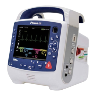
ZOLL Propaq MD Operator's Manual
Portable defibrillator
Hide thumbs
Also See for Propaq MD:
- Operator's manual (326 pages) ,
- Service manual (142 pages) ,
- Quick reference manual (10 pages)
Table of Contents
Advertisement
Quick Links
Advertisement
Table of Contents

Subscribe to Our Youtube Channel
Related Manuals for ZOLL Propaq MD


Summary of Contents for ZOLL Propaq MD
- Page 1 Propaq MD Operator’s Guide ® December 2011 9650-0802-06 Rev. A...
- Page 2 ZOLL, pedi•padz, and stat•padz are registered trademarks, and SurePower and Rectilinear Biphasic are trademarks of ZOLL Medical Corporation. Propaq and Smartcuf are registered trademarks, and SureBP is a trademark of Welch Allyn Inc. Nellcor and OxiMax are trademarks of Covidien. Oridion, Microstream, FilterLine, and CapnoLine are registered trademarks of Oridion Systems, Ltd.
-
Page 3: Table Of Contents
Operator’s Guide Updates ....................1-2 Unpacking ........................... 1-2 Symbols Used on the Equipment ..................1-3 Conventions ........................1-6 Propaq MD Indications for Use ................... 1-6 Manual Defibrillation ....................1-7 ECG Monitoring ......................1-7 External Transcutaneous Pacing ................1-7 Non-Invasive Blood Pressure Monitoring ..............1-8 Temperature Monitoring ..................... - Page 4 Navigation Keys ....................... 2-15 Display Brightness ....................2-15 Common Tasks ......................... 2-16 Changing the Display Brightness ................2-16 Replacing a Battery Pack on the Propaq MD ............2-16 Using Treatment Buttons ..................2-17 Chapter 3 Monitoring Overview Propaq MD Monitoring Functions ..................3-1 ECG ..........................
- Page 5 Preparing the Patient for Electrode Application ............6-2 Applying Electrodes to the Patient ................6-3 Connecting the ECG Cable To the Propaq MD Unit ........... 6-5 Selecting ECG Waveforms for Display ............... 6-6 Selecting the Waveform Trace Size ................6-8 ECG Monitoring and Pacemakers ..................
- Page 6 Applying a Smart CapnoLine Nasal or Nasal/Oral Cannula ........10-6 Measuring CO2......................... 10-7 Setting CO2 and Respiration Rate Alarms ............... 10-8 Enabling/Disabling Alarms and Setting CO2 Alarm Limits ........10-8 Using the CO2 Parameter Control Panel ..............10-10 System Messages ......................10-11 Patents..........................10-12 www.zoll.com 9650-0802-06 Rev. A...
- Page 7 Specifying the Number of 12-Lead Print Copies ............. 13-10 Specifying the 12-Lead Print Format ..............13-11 Printing 10 Seconds of the Lead ll Waveform Trace ..........13-11 Specifying the 12-Lead Frequency Response ............13-11 9650-0802-06 Rev. A Propaq MD Operator’s Guide...
- Page 8 3 Press Pacer button ....................15-3 4 Set Mode ....................... 15-4 5 Set Pacer Rate ...................... 15-4 6 Turn Pacer On ....................... 15-4 7 Set Pacer Output ....................15-4 8 Determine Capture ....................15-4 9 Determine Optimum Threshold ................15-5 www.zoll.com 9650-0802-06 Rev. A...
- Page 9 Annually ........................18-7 Guidelines for Maintaining Peak Battery Performance ............. 18-7 Cleaning instructions ......................18-8 Cleaning the Propaq MD unit ..................18-8 Cleaning the NIBP Blood Pressure Cuff ..............18-8 Cleaning SpO2 Sensors ................... 18-9 Cleaning Cables and Accessories ................18-9 Loading Recorder Paper ...................
- Page 10 Randomized Multicenter Clinical Trial for Defibrillation of Ventricular Fibrillation (VF) and Ventricular Tachycardia (VT) ................A-23 Randomized Multi-Center Clinical trial for Cardioversion of Atrial Fibrillation (AF) ....................A-24 Synchronized Cardioversion of Atrial Fibrillation ............A-25 Electromagnetic Compatibility Guidance and Manufacturer’s Declaration .......A-27 Appendix B Accessories viii www.zoll.com 9650-0802-06 Rev. A...
-
Page 11: Chapter 1 General Information
The Propaq MD has a patient data review and collection system that allows you to view, store, and transfer patient data. The Propaq MD unit contains a printer and USB port, which you can use to print the data and transfer it to a PC. -
Page 12: Propaq Md Optional Features
How to Use This Manual The Propaq MD Operator's Guide provides information operators need for the safe and effective use and care of the Propaq MD product. It is important that all persons using this device read and understand all the information contained within. -
Page 13: Symbols Used On The Equipment
Temperature limitation. Conformité Européenne Complies with medical device directive 93/42/EEC. Type B patient connection. Type BF patient connection. Type CF patient connection. Defibrillator-proof type BF patient connection. Defibrillator-proof type CF patient connection. Fusible link. 9650-0802-06 Rev. A Propaq MD Operator’s Guide... - Page 14 Power On/Off Protective earth (ground). Contains lithium. Recycle or dispose of properly. R E C Y C L E Keep away from open flame and high heat. Do not open, disassemble, or intentionally damage. Do not crush. www.zoll.com 9650-0802-06 Rev. A...
- Page 15 (WEEE). Do not dispose of in unsorted trash. Date of manufacture. Use by. Latex-free. Do not reuse. Do not fold. Not sterile. Manufacturer. Authorized representative in the European Community. Serial Number. Catalogue number. Consult instructions for use. 9650-0802-06 Rev. A Propaq MD Operator’s Guide...
-
Page 16: Conventions
Propaq MD. The Propaq MD is also intended for use by (or on the order of) physicians at the scene of an emergency or in a hospital emergency room, intensive care unit, cardiac care unit, or other similar areas of a hospital. -
Page 17: Manual Defibrillation
The patient population will range from newborn (neonate) to adult. ECG Monitoring The Propaq MD is intended for use to monitor and/or record 3-, 5-, or 12-lead ECG waveform and heart rate, and to alarm when heart rate is above or below limits set by the operator. The patient population will range from newborn (neonate) to adult, with and without heart dysfunction. -
Page 18: Non-Invasive Blood Pressure Monitoring
The patient population will range from newborn (neonate) to adult. Respiration Monitoring The Propaq MD is intended for use to continuously monitor respiration rate and to alarm if the rate falls outside of the range set by the operator. Because the measurement method actually measures respiratory effort, apnea episodes with continued respiratory effort (such as obstructive apnea) may not be detected. -
Page 19: Co2 Monitoring
Propaq MD Product Functions Defibrillator Function The Propaq MD contains a direct current (dc) defibrillator capable of delivering up to 200 joules. It may be used in synchronized mode to perform synchronized cardioversion using the patient’s R-wave as a timing reference. The unit uses paddles or disposable, pregelled electrodes for defibrillation. -
Page 20: Ecg Monitoring
The ECG bandwidth is user selectable. Electrodes The Propaq MD will defibrillate, cardiovert, and monitor ECG using hands-free therapy electrodes. The Propaq MD will pace using ZOLL hands-free therapy electrodes. Energy Select, Charge and Shock controls are located on the paddles and front panel. When using hands-free therapy electrodes, you must use the controls on the front panel of the unit. -
Page 21: Batteries
You can charge the battery by either of the following methods: Internal charging — plug the Propaq MD into an auxiliary power adapter to automatically • begin charging the installed battery pack. The front panel battery indicator operates as... -
Page 22: Ready For Use (Rfu) Indicator
NFORMATION Ready For Use (RFU) Indicator The Propaq MD has an RFU indicator on the front panel that indicates if the device is ready for use. The RFU indicator has three states which are described in the following table. State... -
Page 23: Warnings
Warnings For safety, the Propaq MD automatically disarms if left charged for more than 60 seconds if the shock button ( ) is not pressed. Warnings General Federal (U.S.A.) law restricts this defibrillator to sale by or on the order of a physician. -
Page 24: Ecg Monitoring
QRS complex. Do not place electrodes directly over an implanted pacemaker. The Propaq MD unit detects ECG electrical signals only. It does not detect a pulse (effective circulatory perfusion). Always verify pulse and heart rate by physical assessment of the patient. -
Page 25: Defibrillation
Warnings Defibrillation The ZOLL Propaq MD can deliver 200 joules of electrical energy. If this electrical energy is not discharged properly, as described in the this manual, the electrical energy could cause personal injury or death to the operator or bystander. -
Page 26: Pacing
In some instances the beat may appear as a relatively normal looking QRS pulse. Mechanical capture can be verified by checking for signs of increased blood flow i.e., reddening of the skin, palpable pulses, increased blood pressure, etc. Continuously observe 1-16 www.zoll.com 9650-0802-06 Rev. A... -
Page 27: Pulse Oximeter
Warning! This device can only be used for external pacing of patients and cannot be used for internal pacing. Do not connect internal pacing lead wires to the Propaq MD defibrillator. Pulse Oximeter Keep the ZOLL finger probe clean and dry. -
Page 28: Noninvasive Blood Pressure
Blood pressure measurement results may be affected by the position of the patient, his or her physiological condition and other factors. Substitution of a component different from that supplied by ZOLL (e.g., cuff, hoses, etc.) may result in measurement error. Use only ZOLL-approved cuffs and hoses. To avoid the risk of intravenous line misconnection and possible introduction of air into a patient’s blood, do not... -
Page 29: Co2
If the Low Battery indication occurs at any time during operation, immediately replace the battery pack. If the LOW BATTERY icon appears, plug the Propaq MD unit into a power source or install a fully charged battery pack. When the warning low battery shutdown prompt appears, immediately replace the battery pack with a fully charged pack or plug the Propaq MD unit into a power source, as unit shut down due to a low battery condition is imminent. -
Page 30: Operator Safety
NFORMATION Operator Safety The Propaq MD can deliver 200 joules of electrical energy. If this electrical energy is not discharged properly, as described in this manual, the electrical energy could cause personal injury or death to the operator or bystanders. -
Page 31: Patient Safety
To ensure patient safety, do not place the monitor in any position that might cause it to fall on the patient. To ensure patient safety, connect the Propaq MD only to equipment with circuits that are electrically isolated. Use only high-quality ECG electrodes. ECG electrodes are for rhythm acquisition only; you cannot use ECG electrodes for defibrillation or pacing. -
Page 32: Cautions
If the Propaq MD unit is powered off for less than 2 minutes, all patient monitoring parameter settings will be retained. If the unit has been powered off for at least two minutes, it will be 1-22 www.zoll.com... -
Page 33: Fda Tracking Requirements
• donated, resold, or otherwise distributed to a different organization • If any such event occurs, contact ZOLL Medical Corporation in writing with the following information: 1. Originator's organization – Company name, address, contact name, and contact phone number... -
Page 34: Software License
1. Grant of License: In consideration of payment of the software license fee which is part of the price paid for this product ZOLL Medical Corporation grants the Purchaser a non- exclusive license, without right to sublicense, to use the system software in object-code form only. - Page 35 Returning a unit for service Before sending a unit to the ZOLL Technical Service Department for repair, obtain a service request (SR) number from the service representative. Remove the battery pack from the unit. Pack the unit with its cables and battery in the original containers (if available) or equivalent packaging.
-
Page 36: The Zoll Serial Number
“A” for January, “B” for February, “C” for March, and so on through “L” for December. The product serial number is a unique set of alphanumeric characters that ZOLL assigns to each individual unit. -
Page 37: Chapter 2 Product Overview
Chapter 2 Product Overview Defibrillator Controls and Indicators 9650-0802-06 Rev. A Propaq MD Operator’s Guide 2–1... -
Page 38: The Front Panel
For connecting the device to a docking station. The Front Panel The front panel of the Propaq MD device includes the display screen, quick access keys, battery and auxiliary power indicators, Ready For Use (RFU) indicator, and the defibrillation front panel buttons: Pacer, Sync, Select Energy, Charge, and Shock ( ). - Page 39 To discharge the defibrillator when using paddles (internal or external) with discharge buttons, press and hold the SHOCK buttons on the paddles. NIBP button Starts/stops an NIBP measurement. Snapshot button Records 24 seconds of numeric and waveform data. 9650-0802-06 Rev. A Propaq MD Operator’s Guide 2–3...
-
Page 40: Display Screen
Quick access keys • Waveform source • Color-coded waveforms and ECG lead identifiers • numeric data • Heart rate numeric data • Respiration rate numeric data • Temperature numeric data • Non-invasive blood pressure numeric data • 2–4 www.zoll.com 9650-0802-06 Rev. A... - Page 41 NIBP data data Current temp Respiration rate Figure 2-2. Propaq MD Display Screen Color coding To differentiate information for various parameters, the unit displays each type of information in a specific user-configurable color. 9650-0802-06 Rev. A Propaq MD Operator’s Guide...
-
Page 42: Battery Status And Auxiliary Power Indicators
Note: Upon powering up the Propaq MD unit, the battery capacity will be displayed within approximately 15 seconds under normal conditions. Under some circumstances, such as activating the defibrillator immediately after the unit is turned on, the battery icon may display less than one hour battery capacity for up to two minutes after exiting the defibrillation mode. -
Page 43: Patient Cables And Connectors
NIBP Exhaust Figure 2-3. Patient Cable Connectors on Left Side of Unit Temp Figure 2-4. Patient Cable Connectors on Right Side of Unit 9650-0802-06 Rev. A Propaq MD Operator’s Guide 2–7... - Page 44 Temp For connecting temperature probe(s). Multifunction Cable (MFC) For connecting paddles or ZOLL hands-free therapy and pacing electrodes. For connecting IBP cable(s). Multifunction Cable (MFC) The unit ships with an MFC that is used to defibrillate the patient. Any other cables that ship with your unit depend on the options you have purchased.
-
Page 45: External Paddles
Attach the MFC from the Propaq unit to the connector at the base of the APEX paddle. 1. Align MFC as shown. 2. Insert MFC into APEX handle. Figure 2-6. Attaching the MFC to the APEX Paddle 9650-0802-06 Rev. A Propaq MD Operator’s Guide 2–9... - Page 46 SHOCK Buttons CHARGE RECORDER Button Button ENERGY Charge Ready SELECT Indicator Buttons Connector and RELEASE button for STERNUM Paddle APEX Paddle Figure 2-8. External Paddles 2–10 www.zoll.com 9650-0802-06 Rev. A...
-
Page 47: Auxiliary Power Adapter
Auxiliary Power Adapter The auxiliary power adapter is used as backup power to operate the Propaq MD. When it is connected to the Propaq, it powers the unit and charges the battery that is installed in the Propaq. -
Page 48: Navigating The Display Screen
Navigating the Display Screen You can access the Propaq MD functions using the quick access keys that are located on the left side of the display screen, and the navigation keys that are located on the right side of the front panel. - Page 49 Navigating the Display Screen Table 2-3. Propaq MD Quick Access Keys Quick access key Description Lead Selects the ECG input source for the first waveform trace. I, II, III... 12 lead Displays the 12-lead monitoring screen. Turns CO on and off.
- Page 50 HAPTER RODUCT VERVIEW Table 2-3. Propaq MD Quick Access Keys Quick access key Description Transfer Log Transfers the current data in the log to a USB drive. Clear Log Deletes the current data in the log. Acquire Collects 10 seconds of 12-lead data for print.
-
Page 51: Navigation Keys
Navigating the Display Screen Table 2-3. Propaq MD Quick Access Keys Quick access key Description Alarm Cancel Suspends the current alarm. Limits Displays the current alarm settings. Limits Disarm Safely discharges the defibrillator internally. No energy is delivered to the patient. -
Page 52: Common Tasks
Replacing a Battery Pack on the Propaq MD This section describes how to replace a battery pack on the Propaq MD. Replacing a Battery Pack on the Propaq MD To remove a battery pack, use your fingers to grasp and raise the latch and pull the battery pack out of the compartment. -
Page 53: Using Treatment Buttons
You can also customize up to 9 treatment buttons by pressing the Setup quick access key ( and then selecting Supervisor>Log>Treatment Options. Highlight Define Custom Labels, and then can customize up to 9 buttons. 9650-0802-06 Rev. A Propaq MD Operator’s Guide 2–17... - Page 54 HAPTER RODUCT VERVIEW 2–18 www.zoll.com 9650-0802-06 Rev. A...
-
Page 55: Chapter 3 Monitoring Overview
If the Propaq MD unit is powered off for less than 2 minutes, all patient monitoring parameter settings are retained. If the Propaq MD unit is powered off for 2 minutes or longer, the unit operates as if there is a New Patient and all patient-specific parameters (alarm limits, defibrillator energy, etc.) are reset to their default values. -
Page 56: Ecg
, or Pads and so on, in this area. You can configure the Propaq MD unit to display up to four ECG waveform traces. In addition to being able to specify the ECG source for each waveform trace, you can adjust the display scale of those traces to make them easier to view. -
Page 57: Capnography (Co2)
Monitoring Display Options The Propaq MD unit gives you great flexibility in how you display a patient’s vital signs information. By pressing the Display/Home button ( ) on the front panel, you can successively display the patient’s vital signs information in these three windows:... - Page 58 Trends Status window. The Trends Status window reports the patient’s vital sign measurements, which the Propaq MD logs automatically at a configurable interval (see the following chapter, Trends, for more detailed information about the Trends Status window). The primary ECG waveform trace appears above the Trends report: www.zoll.com...
- Page 59 I, II, 1 cm/mV III... NIBP mmHg NIBP Trends (96) SpO2 NIBP Time HR/PR RR/BR mmHg br/min EtCO2 mmHg 12:30:21 122/60 (85) 12:25:21 122/60 (85) 12:20:21 122/60 (85) SpO2 12:15:21 124/63 (86) ºF 98.6 9650-0802-06 Rev. A Propaq MD Operator’s Guide...
- Page 60 (15) Press the Home/Display button to redisplay the Primary Display window. Note: When the Propaq MD unit is displaying the Defibrillation or Pacing Control panels, the unit will not allow the display the Large Numerics Display window. www.zoll.com 9650-0802-06 Rev. A...
-
Page 61: Configuring The Waveform Display
SpO2 or IBP channels , or The Propaq MD unit can also cascade a trace onto the adjoining trace area to double the duration of the trace display. On the Waveform Display window, to insert a new trace ( Insert... - Page 62 ECG lead aVR, and fourth trace for EtCO2 (a capnogram). Notice that when the third trace is inserted, the numeric displays move to the right side of the window to allow more room for the waveform traces. www.zoll.com 9650-0802-06 Rev. A...
- Page 63 Source 1 cm/mV Pads III... Insert Cascade mmHg mmHg SpO2 NIBP (96) ºF 98.6 03/23/2009 12:34:56 Adult 00:17:43 I, II, 1 cm/mV III... NIBP mmHg (96) EtCO2 mmHg 1 cm/mV SpO2 ºF 98.6 9650-0802-06 Rev. A Propaq MD Operator’s Guide...
- Page 64 SpO2 Resp EtCO2 mmHg 1 cm/mV Insert Cascade SpO2 Remove ºF 98.6 03/23/2009 12:34:56 Adult 00:17:43 I, II, 1 cm/mV III... NIBP mmHg (96) 1 cm/mV EtCO2 mmHg 0 to 60 mmHg SpO2 ºF 98.6 3-10 www.zoll.com 9650-0802-06 Rev. A...
-
Page 65: Chapter 4 Trends
A patient alarm occurs and the Trend on Alarm option is on • The Propaq MD unit can store at least 24 hours of trend information when logged at a 1 minute trend interval. You can view, print, or save to external memory all logged trend information. -
Page 66: Displaying And Printing Trend Information
Press the Print Trend Summary button in the Trend Settings menu. To select which trends to print for the current patient, press the Log quick access key ( Print then press the Print Trends button ( Trends www.zoll.com 9650-0802-06 Rev. A... -
Page 67: Changing The Trends Status Window Display
Vital Signs Displayed Resp HR, SpO2, RR, EtCO2, FiCO2 NIBP HR, SpO2, NIBP, RR IBP1 HR, SpO2, IBP1, RR IBP2 HR, SpO2, IBP2 RR IBP3 HR, SpO2, IBP3, RR Temp HR, SpO2, T1, T2, 9650-0802-06 Rev. A Propaq MD Operator’s Guide... - Page 68 HAPTER RENDS www.zoll.com 9650-0802-06 Rev. A...
-
Page 69: Chapter 5 Alarms
Visual Alarm Indicators In addition to status messages that appear on the display, the Propaq MD unit lights the red or yellow LED on the front panel to indicate the priority level of the highest-priority active alarm. -
Page 70: Audible Alarm Indicators
Alarm Indicator Self-Test The Propaq MD unit performs a self-test of the audio and visual alarm indicators upon power- up. To ensure that the alarms and alerts are functioning properly, verify that two alarm tones are heard and the green, yellow, and red LEDs are illuminated upon power up. -
Page 71: Patient Alarm Display
When a patient’s vital signs measurements trigger an alarm, in addition to sounding the patient alarm, the Propaq MD unit displays an alarm message, and changes the display characteristics of the monitoring function’s numeric display (the alarming parameter appears in red against a white background). -
Page 72: Equipment Alert Display
HAPTER LARMS Equipment Alert Display When a problem with the Propaq MD unit or an attached sensor triggers an alert, in addition to sounding an equipment alert, the Propaq MD unit displays an alert message (yellow background, black text). Warning! Always respond immediately to a system alarm since the patient may not be monitored during certain alert conditions. -
Page 73: Re-Enabling An Alarm
No alarms will sound while alarms are suspended; however, if an alarm occurs during the suspension period, the Propaq MD unit will display visual alarm indicators -- alarm messages in the message area (white text on a red background) and red/white numeric displays). -
Page 74: The Alarm Suspension Timer
During an alarm suspension, the window displays an alarm suspension timer at the top of the display next to the message area: Alarm Suspension Timer 03/23/2009 12:34:56 Adult 00:17:43 1:30 EtCO2 Low Alarm I, II, 1 cm/mV III... mmHg mmHg mmHg NIBP SpO2 (96) ºF 98.6 www.zoll.com 9650-0802-06 Rev. A... -
Page 75: Alarm Options
Alarm Options Alarm Options The Propaq MD unit provides alarm options that you can specify through the Supervisor parameter control panel (access to Supervisor is passcode-controlled). Press the More quick access key ( ), press the Setup quick access key (... -
Page 76: Selecting Default Alarm Limits
Do not set alarm limits to such extreme values that render the alarm system useless. Setting Alarm Limits Relative to the Patient -- Stat Set Option The Propaq MD unit also allows you to set all alarm limits relative to the patient’s current vital signs measurements by performing the following actions: 1. - Page 77 Limit = Numeric + 5 (mmHg) Temp Entire range Limit = Numeric + 0.5 Limit = Numeric – 0.5 (°C) Temp Entire range Limit = Numeric + 0.9 Limit = Numeric – 0.9 (°F) 9650-0802-06 Rev. A Propaq MD Operator’s Guide...
- Page 78 HAPTER LARMS 5-10 www.zoll.com 9650-0802-06 Rev. A...
-
Page 79: Chapter 6 Monitoring Ecg
This chapter describes how to use the Propaq MD unit to monitor ECG. Propaq MD units can perform ECG monitoring through 3-, 5-, or 12-lead ECG patient cables, Multi-Function Pads, or standard defibrillation paddles. The use of an ECG patient cable and electrodes is required, however, to monitor ECG during pacing. -
Page 80: Ecg Monitoring Setup
Apply the electrode pads to the patient. Connect each lead of the ECG cable to the appropriate electrode. Insert the patient cable plug into the ECG input connector on the Propaq MD unit. Select the ECG waveforms to be displayed on the waveform trace display screen. -
Page 81: Applying Electrodes To The Patient
LA/Black Electrode L/Yellow Electrode Place near patient’s left mid-clavicular line, directly below clavicle. LL/Red Electrode F/Green Electrode Place between 6th and 7th intercostal space on patient’s left mid-clavicular line. Figure 6-1 3-Lead Electrode Placement 9650-0802-06 Rev. A Propaq MD Operator’s Guide... - Page 82 V3 -- Midway between V2 and V4 leads. V4 -- 5th intercostal space at mid-clavicular line. V5 -- Same transverse level as V4 at left anterior-axillary line. V6 -- Same transverse level as V4 at left mid-axillary line. www.zoll.com 9650-0802-06 Rev. A...
-
Page 83: Connecting The Ecg Cable To The Propaq Md Unit
Connecting the ECG Cable To the Propaq MD Unit The Propaq MD unit accepts Welch Allyn Propaq ECG cables as well as ZOLL Propaq MD ECG cables. Connect the ECG cable to the ECG connector on the left side of the Propaq MD unit as follows: Figure 6-3 Connecting ECG Cable to Propaq MD Unit 9650-0802-06 Rev. -
Page 84: Selecting Ecg Waveforms For Display
ONITORING Selecting ECG Waveforms for Display You can fit up to four waveforms on the Propaq MD display. The first waveform at the top of the display is always an ECG waveform. In the following example, Lead (RA-LL), is the source of the ECG waveform trace: The are two ways to specify which ECG lead is the source of the primary waveform trace. - Page 85 LEAD FAULT. For more information on how to configure the display of waveforms on the Propaq MD unit, see Chapter 3, Monitoring Overview. 9650-0802-06 Rev. A...
-
Page 86: Selecting The Waveform Trace Size
ONITORING Selecting the Waveform Trace Size The Propaq MD unit allows you to select the waveform trace size to adjust the size of displayed the ECG waveform. To select the waveform size, use the navigation keys to highlight and select the trace size that... -
Page 87: Ecg Monitoring And Pacemakers
, implantable pacemaker signals may cause inaccurate QRS detection and it may be desirable to turn the Pacer Indicator on. ECG System Messages When monitoring ECG, the Propaq MD unit may display the following messages: System Message Cause LEAD FAULT The current ECG source lead is defective (check lead and replace, if necessary). - Page 88 HAPTER ONITORING 6-10 www.zoll.com 9650-0802-06 Rev. A...
-
Page 89: Chapter 7 Monitoring Respiration (Resp) And Heart Rate (Hr)
Chapter 7 Monitoring Respiration (Resp) and Heart Rate (HR) This chapter describes how to use the Propaq MD unit to monitor Respiration ( ) and Heart Resp Rate ( The Propaq MD unit displays Respiration ) and Heart Rate ( ) meters. -
Page 90: Respiration/Breath Rate Meter
Chapter 7 Monitoring Respiration (Resp) and Heart Rate (HR) Respiration/Breath Rate Meter If enabled, the Propaq MD unit displays the patient’s respiration in the Respiration/Breath Rate Meter. The respiration meter displays the respiration rate that it derives, by default, from the unit’s monitoring function. -
Page 91: Configuring Respiration (Rr/Br) Alarms And Settings
ECG monitoring source for the Respiration rate. Enabling/Disabling RR/BR Alarms and Setting Alarm Limits When enabled, the Propaq MD unit sounds alarms whenever the patient’s respiration rate is above or below the specified respiration rate alarm limits. -
Page 92: Using The Resp Parameter Control Panel
-- selects the Resp lead, Lead I (RA-LA) or Lead II (RA-LL), from which the • Resp Lead Propaq MD unit calculates the respiration rate. Resp Lead selection is independent of ECG Lead selection. sets the respiratory sweep speed on the display. -
Page 93: Heart Rate Meter
Configuring Heart Rate (HR) Meter Alarms The Propaq MD unit allows you to enable and disable the Heart Rate (HR) alarm, to set alarm limits, and to select a Heart Rate tone. 9650-0802-06 Rev. A... -
Page 94: Enabling/Disabling Hr Alarms And Setting Alarm Limits
Chapter 7 Monitoring Respiration (Resp) and Heart Rate (HR) Enabling/Disabling HR Alarms and Setting Alarm Limits When enabled, the Propaq MD unit sounds alarms whenever the patient’s heart rate is above or below the specified heart rate alarm limits. To enable (or disable) HR alarms and set Upper and Lower alarm limits, you can either do so through the Alarms quick access key ( ) or the HR/PR Parameter Control Panel. -
Page 95: Using The Heart Rate Parameter Control Panel
ECG Sweep Speed 25 mm/s Figure 7-2 HR/PR Parameter Control Panel Selecting the prompt displays the HR/PR Alarm Settings menu, on which you HR/PR Alarm can enable/disable Heart Rate alarms and set alarm limits. 9650-0802-06 Rev. A Propaq MD Operator’s Guide... - Page 96 Chapter 7 Monitoring Respiration (Resp) and Heart Rate (HR) www.zoll.com 9650-0802-06 Rev. A...
-
Page 97: Chapter 8 Monitoring Non-Invasive Blood Pressure (Nibp)
Monitoring Non-Invasive Blood Pressure (NIBP) The Propaq MD NIBP input is Type CF defibrillator proof. This chapter describes how to use the Propaq MD unit to perform Non-Invasive Blood Pressure (NIBP) measurements using an inflatable cuff to measure arterial pressure. -
Page 98: How Does Nibp Work
How does NIBP Work? The blood pressure cuff and hose connect to the Propaq MD unit through the NIBP connector on the side panel of the unit. The NIBP button on the front panel of the unit allows you to initiate and terminate blood pressure measurements, which are displayed in the NIBP area of the monitor. -
Page 99: The Nibp Numeric Display
The NIBP Numeric Display When NIBP monitoring has been set up and the Propaq MD unit has begun taking NIBP measurements, the systolic, diastolic, and mean blood pressure measurements appear on the NIBP numeric display as follows:... -
Page 100: Selecting The Nibp Cuff
40 percent of the limb circumference. Caution Use only hoses and cuffs that are approved by ZOLL Medical Corporation. See Appendix B, Accessories, for a listing of the approved hoses and cuffs. Use the following guidelines when selecting the appropriate hose and cuff:... - Page 101 Using a cuff that is too large results in measurements lower than the patient’s actual blood pressure. The Propaq MD unit uses the same definitions of Neonates, Pediatrics, and Adults as defined in the AAMI SP10:2002 standard:...
-
Page 102: Connecting The Nibp Cuff
RESSURE Connecting the NIBP Cuff Connecting the NIBP cuff requires you to attach the inflation hose to the Propaq MD unit and the NIBP cuff. To use the SureBP feature, which enables the Propaq MD unit to measure blood pressure on cuff inflation, you must use the FlexiPort cuff and dual lumen (two-tube) adaptor and hose. - Page 103 Connecting the NIBP Cuff Attach a single lumen hose as follows: Figure 8-2 Attaching Single Lumen Hose to the Propaq MD Unit 9650-0802-06 Rev. A Propaq MD Operator’s Guide...
-
Page 104: Applying The Cuff To The Patient
Check that the cuff ends between the range lines marked on the cuff. If they do not line up, use a different size cuff. Wrap the deflated cuff snugly around the limb without impeding blood flow. Ensure that the hose is routed to avoid kinking or compression. www.zoll.com 9650-0802-06 Rev. A... -
Page 105: Ensuring Correct Cuff Inflation Settings
80 mmHg 60 mmHg 140 mmHg 90 mmHg 70 mmHg 160 mmHg 100 mmHg 80 mmHg 180 mmHg 110 mmHg 90 mmHg 200 mmHg 120 mmHg 100 mmHg 220 mmHg 130 mmHg 110 mmHg 9650-0802-06 Rev. A Propaq MD Operator’s Guide... -
Page 106: Configuring Nibp Alarms And Settings
The maximum cuff inflation pressure for neonates is 153 mmHg. Warning! Before using the Propaq MD unit to monitor a new patient, power down the unit for at least 2 minutes to reset all patient parameters and eliminate all adjustments made for the previous patient. - Page 107 Upper: 110 mmHg Upper: 22-220 mmHg Pediatric Lower: 35 mmHg Lower: 20-128 mmHg Upper: 100 mmHg Upper: 22-130 mmHg Neonate Lower: 30 mmHg Lower: 10-108 mmHg Upper: 70 mmHg Upper: 12-110 mmHg 9650-0802-06 Rev. A Propaq MD Operator’s Guide 8-11...
-
Page 108: Using The Nibp Parameter Control Panel
Use the navigation keys to highlight and select the NIBP numeric display to display the NIBP Parameter Control Panel: NIBP Lower Upper NIBP Systolic Alarm NIBP Diastolic Alarm NIBP MAP Alarm NIBP Mode Manual NIBP Auto Mode Interval 5 min SmartCuf On/Off Start TurboCuf Figure 8-4 NIBP Parameter Control Menu 8-12 www.zoll.com 9650-0802-06 Rev. A... - Page 109 ). To repeat the NIBP measurement, you must press the NIBP key again (select Manual In Automatic Mode, the Propaq MD unit takes the first of a series of NIBP measurements when timer expires, and then repeats the NIBP measurement at this specified Auto Interval interval.
- Page 110 Start/Stop TurboCuf Selecting Start TurboCuf starts Short-term Automatic (STAT) NIBP measurements. The Propaq MD unit begins its first NIBP measurement, after which it continues to perform as many NIBP measurements as possible over a 5-minute period. Select Stop TurboCuf to immediately stop STAT measurements.
-
Page 111: Nibp System Messages
NIBP System Messages NIBP System Messages When monitoring NIBP, the Propaq MD unit may display the following messages: System Message Cause READING IN PROGRESS The unit is taking an NIBP measurement and functioning normally. READING STOPPED The unit has stopped an NIBP measurement, because the operator has pressed the NIBP button and cancelled the measurement. - Page 112 (NIBP) HAPTER ONITORING NVASIVE LOOD RESSURE 8-16 www.zoll.com 9650-0802-06 Rev. A...
-
Page 113: Chapter 9 Monitoring Pulse Oximetry (Spo2)
Monitoring Pulse Oximetry (SpO The Propaq MD SpO input is Type CF defibrillator proof. This chapter describes how to use the Propaq MD unit to monitor Pulse Oximetry (SpO The Propaq MD pulse oximeter continuously and noninvasively measures the oxygen saturation (SpO ) of arterial blood at a peripheral site, such as the foot, toe, or finger. -
Page 114: Warnings -- Spo 2 , General
Dyes or any substance containing dyes that alter arterial pigmentation might cause erroneous readings. Do not use the Propaq MD pulse oximeter or oximeter sensors during magnetic • resonance imaging (MRI). Induced current could cause burns. The pulse oximeter might affect the MRI image and the MRI unit might interfere with the accuracy of oximetry measurements. -
Page 115: Spo 2 Setup And Use
For more information, refer to the Accessories section of this chapter, which provides a list of ZOLL-approved reusable and single-use SpO sensors for adult, pediatric, and neonate patients. -
Page 116: Applying A Reusable Spo 2 Sensor
To ensure accurate data, you must have complete coverage of the detector window (see previous figure). Note: With smaller digits, the digit may not need to be pushed all the way to the stop to completely cover the detector window. www.zoll.com 9650-0802-06 Rev. A... -
Page 117: Applying A Single-Use Sensor
(for example, as a result of externally applied coloring such as nail polish, dye, or pigmented cream) to permit appropriate light transmission. If any of these situations occurs, reposition the sensor or choose an alternate sensor for use on a different site. 9650-0802-06 Rev. A Propaq MD Operator’s Guide... -
Page 118: Connecting The Spo Sensor
1. When using a sensor extension cable, inspect the cable before use. Replace the cable if it shows any signs of wear, breakage, or fraying. Plug the sensor extension cable into the SpO socket on the side of the Propaq MD unit: Figure 9-1 Connecting the SpO... -
Page 119: Displaying Spo 2 Measurements
If the message, SENSOR FAILURE, appears, the sensor is either incompatible with the Propaq MD unit, or it is not working, and you will need to replace the sensor. A blip bar appears on the right side of the SpO numeric display window. -
Page 120: Setting Upper And Lower Systolic Alarm Limits
SpO2 Lower Upper CO2 Scale SpO2 Alarm 0 to 30 mmHg Response 0 to 60 mmHg Normal 0 to 100 mmHg HR/PR Tone 0 to 150 mmHg Figure 9-4 SPO2 Parameter Control Menu www.zoll.com 9650-0802-06 Rev. A... -
Page 121: Specifying The Spo Response Time
The unit allows you enable or disable the tone that the monitor uses to indicate detection of the patient’s pulse: (no tone sounds). The default tone is System Messages The Propaq MD unit may display the following system messages when monitoring SpO System Message Cause INITIALIZING The SpO pulse oximeter is initializing. -
Page 122: Functional Testers And Patient Simulators
For a properly functioning monitor, this difference will be reproducible over time and from monitor to monitor within the performance specifications of the test device. 9-10 www.zoll.com 9650-0802-06 Rev. A... -
Page 123: Overview
Chapter 10 Monitoring CO This chapter describes how to use the Propaq MD unit to monitor End Tidal Carbon Dioxide (EtCO ), breath rate, and Fractional Inspired Carbon Dioxide (FiCO ). These options use the same connector on the Propaq MD unit and may be used interchangeably. -
Page 124: Co2 Monitoring Setup And Use
Apply the Filterline airway adaptor or Smart CapnoLine Nasal or Nasal/Oral cannula to the patient. Check that the Propaq MD unit is set up for the correct patient type -- Adult, Pediatric, or Neonate. Configure alarms (if the current alarm settings are not appropriate) and other CO features. -
Page 125: Selecting The Co2 Sampling Line
You can use the following Oridion Microstream accessories for sidestream CO monitoring with the Propaq MD unit: Table 7-1. Oridion Microstream CO Sampling Lines for use with Propaq MD units. Accessory Type Part Number FilterLine Set (Adult/Pediatric), box of 25... -
Page 126: Connecting The Co2 Sampling Lines
ONITORING Connecting the CO Sampling Lines To connect the FilterLine or Smart CapnoLine: 1. Slide open the Propaq MD unit’s CO inlet port cover. Put the fitting at the end of the sidestream tubing over the CO inlet port connector. -
Page 127: Applying A Filterline Set
To prevent moisture from draining into the sample tubing, ensure that the sampling tube exits from the top of the airway adapter, not its bottom or sides. See the following figure. 9650-0802-06 Rev. A Propaq MD Operator’s Guide 10-5... -
Page 128: Applying A Smart Capnoline Nasal Or Nasal/Oral Cannula
Placing the Cannula onto the Patient Place the oral/nasal cannula onto the patient as follows: Caution Dispose of Microstream EtCO consumables according to standard operating procedures or local regulations for the disposal of contaminated medical waste. 10-6 www.zoll.com 9650-0802-06 Rev. A... -
Page 129: Measuring Co2
Check that connections have been made correctly by verifying the display a proper capnogram (the waveform is inserted automatically on the waveform display window). 03/23/2009 12:34:56 Adult 00:17:43 I, II, 1 cm/mV III... 0 to 60 mmHg mmHg mmHg SpO2 NIBP (96) ºF 98.6 9650-0802-06 Rev. A Propaq MD Operator’s Guide 10-7... -
Page 130: Setting Co2 And Respiration Rate Alarms
10 M HAPTER ONITORING Setting CO and Respiration Rate Alarms The Propaq MD unit sounds alarms whenever measurements are outside set limits for the following: High and Low EtCO • High and Low Respiration Rate (in Breaths/Minute) • High FiCO •... - Page 131 In high-altitude environments, EtCO values may be lower than values observed at sea level, as described by Dalton’s law of partial pressures. When using the Propaq MD unit in high-altitude environments, it is advisable to adjust EtCO alarm settings accordingly.
-
Page 132: Using The Co2 Parameter Control Panel
On the CO2 Parameter Control Panel, you can select a CO alarm (EtCO2, Breath Rate, or FiCO2). On the selected alarm settings menu, you can enable/disable alarms and set alarm limits (as described previously). You can also set the CO sweep speed. 10-10 www.zoll.com 9650-0802-06 Rev. A... -
Page 133: System Messages
3.13, 6.25, and 12.5 mm/second. The default sweep speed is 6.25 mm/second. System Messages When monitoring CO , the Propaq MD unit may display the following messages: System Message Cause INITIALIZING The unit is initializing the CO... -
Page 134: Patents
10 M HAPTER ONITORING Patents The capnography component of the Propaq MD unit is covered by one or more of the following US patents: 6,428,483; 6,997,880;5,3000,859; 6,437,316; 7,488,229; and their foreign equivalents. Additional patent applications pending. NO IMPLIED LICENSE Possession or purchase of this device does not convey any express or implied license to the... -
Page 135: Chapter 11 Monitoring Invasive Pressures (Ibp)
This chapter describes how to use the Propaq MD unit to monitor invasive pressures (IBP). The Propaq MD unit has three invasive pressure channels: P1, P2, and P3. You can use these channels to measure arterial, venous, or intracranial pressures using invasive transducers with 5uV/V/mmHg sensitivity. -
Page 136: Ibp Setup
• Before you use the Propaq MD unit on a new patient, always turn it off for at least 2 minutes. This clears the previous patient’s trend values, alarm limit settings, and NIBP cuff inflation pressure. -
Page 137: Zeroing The Transducer
IBP channel. Zeroing the Transducer To ensure that the Propaq MD unit measures pressure accurately, you must zero the transducer before each use. If you change or disconnect a transducer, you must zero the new transducer before use. -
Page 138: Rezeroing A Transducer
Check that the unit is open to atmospheric air and that it is properly connected to the unit, then try zeroing the transducer again. The Propaq MD unit will not zero the transducer if it detects pulsation in the pressure channel, if there is too much noise in the signal, or if transducer’s offset is too great. -
Page 139: Displaying Ibp Measurements
MEAN values in the IBP channel’s numeric display and, optionally (if enabled through the unit’s Waveform Select menu) the waveform for that IBP channel: The Propaq MD unit allows you to specify a label that identifies the channel’s IBP measurement, and to select a display format for the numeric display. -
Page 140: Enabling/Disabling Ibp Alarms And Setting Alarm Limits
HAPTER ONITORING NVASIVE RESSURES Enabling/Disabling IBP Alarms and Setting Alarm Limits When enabled, the Propaq MD unit sounds alarms whenever IBP measurements are outside set limits for the following: High and Low Systolic Pressure • High and Low Diastolic Pressure •... -
Page 141: Setting Upper And Lower Diastolic (Dia) Alarm Limits
Lower: 50 mmHg Lower: -30 to 298 mmHg Upper: 110 mmHg Upper: -28 to 300 mmHg Neonate Lower: 35 mmHg Lower: -30 to 298 mmHg Upper: 80 mmHg Upper: -28 to 300 mmHg 9650-0802-06 Rev. A Propaq MD Operator’s Guide 11-7... -
Page 142: Setting Ibp Source Label
Central Venous Pressure Femoral Artery Pressure Intracranial Pressure Labial Artery Pressure Pulmonary Artery Pressure Radial Artery Pressure Umbilical Artery Pressure Umbilical Venous Pressure In the following example, source labels are specified for all three IBP channels: 11-8 www.zoll.com 9650-0802-06 Rev. A... -
Page 143: Ibp System Messages
IBP System Messages IBP System Messages The Propaq MD unit may display the following messages when monitoring IBP: System Message Cause TRANSDUCER FAILURE The IBP probe is damaged and needs to be replaced. INCOMPATIBLE TRANSDUCER The IBP probe is not compatible. See the Appendix B, Accessories, for a list of ZOLL-approved IBP probes. - Page 144 11 M (IBP) HAPTER ONITORING NVASIVE RESSURES 11-10 www.zoll.com 9650-0802-06 Rev. A...
-
Page 145: Chapter 12 Monitoring Temperature
Selecting and Applying Temperature Probes You should use only temperature probes that are approved for use with the Propaq MD unit. See Appendix B, Accessories for a list of ZOLL-approved temperature probes. The use of other probes that do not match the performance specifications of the ZOLL-approved probes may produce incorrect temperature readings. -
Page 146: Connecting The Temperature Probe
To connect the temperature probe, insert the probe’s 1/4” plug into one of the two connection jacks on the side of the Propaq MD unit. Figure 12-1 Connecting the Temperature Probe to the Propaq MD Unit Displaying Temperature When you connect the probe, the unit displays the temperature after a brief pause. The Propaq MD unit displays temperature as a numeric value in the Temperature window. -
Page 147: Enabling/Disabling Temperature Alarms And Setting Alarm Limits
Enabling/Disabling Temperature Alarms and Setting Alarm Limits Enabling/Disabling Temperature Alarms and Setting Alarm Limits When enabled, the Propaq MD unit sounds alarms whenever temperature measurements are outside set limits. You can enable (or disable) temperature alarms and set the upper and lower alarm limits through the Alarms quick access key or the Temp Parameter Control Panel. -
Page 148: Selecting The Temperature Label
Temp Lower Upper T1 Alarm T2 Alarm 7 $ODUP T1 Source Label T2 Source Label Figure 12-2 Temp Parameter Control Panel You can select one of the following labels for each temperature channel: 12-4 www.zoll.com 9650-0802-06 Rev. A... -
Page 149: Temperature System Messages
If you don’t select a label, the Temperature channels appear with the default labels of T1 and Temperature System Messages The Propaq MD unit may display the following messages when monitoring Temperature. Note: The temperature function performs a self test when initially powered on and also performs system tests automatically, every 10 seconds, while this function is active. - Page 150 12 M HAPTER ONITORING EMPERATURE 12-6 www.zoll.com 9650-0802-06 Rev. A...
-
Page 151: Chapter 13 Monitoring 12-Lead Ecg
Monitoring 12-Lead ECG The Propaq MD 12-Lead input is Type CF defibrillator proof. This chapter describes how to use the Propaq MD unit to perform 12-Lead ECG Monitoring. The Propaq MD with the 12-lead ECG Monitoring option provides simultaneous acquisition and storage of 12-lead information. -
Page 152: Entering Patient Information
Patient Age Patient Gender Patient ID Figure 13-1 Patient Info Control Panel The Propaq MD unit uses the name that you enter in the Patient Info panel to label the 12-lead ECG monitoring snapshots that it saves. 13-2 www.zoll.com 9650-0802-06 Rev. A... -
Page 153: Entering The Patient Name And Id
• Clear Saves the characters entered for that parameter and returns you to the • SAVE Patient Info panel. Returns you to the Patient Info panel without saving the characters • Cancel entered. 9650-0802-06 Rev. A Propaq MD Operator’s Guide 13-3... -
Page 154: Entering Patient Age And Gender
Apply the electrodes to the patient. Connect each lead of the ECG cable to the appropriate electrode. Connect the 12-Lead cable to the Propaq MD unit. Observe the patient’s electrocardiogram on the display, and adjust size of the 12-Lead ECG waveform traces, as necessary. -
Page 155: Applying Electrodes To The Patient
International Electrotechnical Commission Patients should be in a resting, supine position when performing 12-Lead ECG monitoring. ZOLL Medical Corporation recommends placing the limb electrodes anywhere along the ankles and wrists. When it is difficult for the patient to remain motionless due to shivering, muscle tremors, or transport vehicle movement, place limb electrodes on the patient’s thorax for better results. - Page 156 V4/C4 Fifth intercostal space, on the patient’s midclavicular line. V5/C5 Patient’s left anterior axillary line, at the horizontal level of V4. V6/C6 Patient’s left midaxillary line, at the same horizontal level as V4 and V5. 13-6 www.zoll.com 9650-0802-06 Rev. A...
-
Page 157: Connecting The 12-Lead Cable
Connecting the 12-Lead Cable Connect the 12-Lead ECG cable to the ECG input connector on the left side of the unit as follows: Figure 13-2 Connecting the 12-Lead ECG Cable 9650-0802-06 Rev. A Propaq MD Operator’s Guide 13-7... -
Page 158: Observing The 12-Lead Waveform Traces
To observe the 12-Lead waveform traces, press . The screen displays all twelve waveform traces, with the size displayed above the waveform traces: 03/23/2009 12:34:56 Adult 00:17:43 1 mV/cm NIBP mmHg (96) EtCO2 mmHg SpO2 Exit SpMet 20.0 ºF 98.6 13-8 www.zoll.com 9650-0802-06 Rev. A... -
Page 159: Printing 12-Lead Waveform Traces
The waveform traces print in either a 3 x 4 format (the default). or a 2 x 6 format: The Propaq MD unit stores a minimum of 32 12-Lead snapshots in a separate log. Once 32 12- lead snapshots are stored, the oldest snapshot in the log is overwritten by subsequent snapshots. -
Page 160: 12-Lead Print And Display Options
Specifying the Number of 12-Lead Print Copies This option allows you to specify that the Propaq MD unit print up to five copies of the 12-lead waveform trace set after pressing . By default, the unit prints only one 12-lead snapshot. -
Page 161: Specifying The 12-Lead Print Format
This option allows you to specify the frequency response of the 12-lead waveform display. You can specify the following trace display ranges: Display Type Frequency Response Diagnostic 0.05 to 150 Hz Filtered Diagnostic 0.25 to 40 Hz 9650-0802-06 Rev. A Propaq MD Operator’s Guide 13-11... - Page 162 13 M 12-L HAPTER ONITORING 13-12 www.zoll.com 9650-0802-06 Rev. A...
-
Page 163: Manual Defibrillation
No portion of the hands should be near the paddle plates. Be sure to use the proper paddles/electrodes based on the size of the patient (adult - large, pediatric - small). 9650-0802-06 Rev. A Propaq MD Operator’s Guide 14–1... -
Page 164: Determine The Patient's Condition Following Local Medical Protocols
Ensure that the paddles are connected to the multi-function cable (MFC) and that the MFC is connected to the Propaq MD unit. Apply a liberal amount of electrolyte gel to the electrode surface of each paddle, and rub the electrode surfaces together to evenly distribute the applied gel. -
Page 165: Charge Defibrillator
Changing the selected energy while the unit is charging or charged causes the defibrillator to disarm itself. Press the Charge button again to charge the unit to the newly selected energy level. 9650-0802-06 Rev. A Propaq MD Operator’s Guide 14–3... -
Page 166: Deliver Shock
Apply a force of 10 - 12 kilograms (22 - 26.4 pounds) to each paddle in order to minimize patient impedance and achieve optimal results. Using your thumbs, simultaneously press and hold both SHOCK buttons (one on each paddle) until energy is delivered to the patient. 14–4 www.zoll.com 9650-0802-06 Rev. A... -
Page 167: Emergency Defibrillation Procedure With Hands-Free Therapy Electrodes
14-2, to readjust the energy settings, charge the unit, and deliver the shock. Emergency Defibrillation Procedure with Hands-Free Therapy Electrodes ZOLL hands-free therapy electrodes are a defibrillation-protected Type BF patient connection. ECG leads are a defibrillation-protected Type CF patient connection. -
Page 168: Begin Cpr Following Medical Protocols
If defibrillation electrodes are not making good contact with the patient’s skin and the pad selection is ECG Lead, the unit issues the message CHECK THERAPY ELECTRODES and does not allow the delivery of energy. 14–6 www.zoll.com 9650-0802-06 Rev. A... -
Page 169: Select Energy Level
Changing the selected energy while the unit is charging or charged causes the defibrillator to disarm itself. Press the CHARGE button again to charge the unit to the newly selected energy level. 9650-0802-06 Rev. A Propaq MD Operator’s Guide 14–7... -
Page 170: Deliver Shock
The delivered energy level is displayed at the bottom of the screen and the shock number (1) displays at the top of the screen and in the Defib Control panel at the bottom of the screen. 14–8 www.zoll.com 9650-0802-06 Rev. A... -
Page 171: Internal Paddles
APPLY PADDLES TO PATIENT. This message verifies that the Discharge button located on the right handle is operating correctly. Press the Energy Select arrows (located on the front panel of the Propaq MD unit) up or down to select 30 Joules. -
Page 172: Synchronized Cardioversion
• Have a second person press and hold on the defibrillator front panel to deliver the test energy to the electrodes. The Propaq MD device unit discharges and displays the message DEFIB SHORT TEST PASSED. Synchronized Cardioversion Warning! Only skilled personnel trained in Advanced Cardiac Life Support and familiar with equipment operation should perform synchronized cardioversion. -
Page 173: Synchronized Cardioversion Procedure
Unless otherwise configured, the unit automatically exits Sync mode after each shock. To reactivate SYNC mode, press the Sync button on the front panel again. Changing the selected energy levels does not cause the unit to leave SYNC mode. 9650-0802-06 Rev. A Propaq MD Operator’s Guide 14–11... -
Page 174: Select Energy Level
When the unit is fully charged, the tone changes to a continuous charge ready tone, the highlighted energy bar graph includes the selected energy, and the shock button lights up. 14–12 www.zoll.com 9650-0802-06 Rev. A... -
Page 175: Deliver Shock
Sync softkey again and follow steps 1 through 3 of this procedure starting on page 14-12, to readjust the energy settings, charge the unit, and deliver shock. You can configure the setting through the Setup>Supervisor>Defib/ Sync after Cardioversion Pacer>Default Settings menu. 9650-0802-06 Rev. A Propaq MD Operator’s Guide 14–13... - Page 176 ANUAL EFIBRILLATION 14–14 www.zoll.com 9650-0802-06 Rev. A...
-
Page 177: External Pacing
Chapter 15 External Pacing When ZOLL hands-free therapy electrodes are used, the patient connection is considered to be defibrillation-protected Type BF. ECG leads are a defibrillation-protected Type CF patient connection. WARNING! Pacing is intended for use on adult patients and on adolescent, child, and infant pediatric patients. -
Page 178: Pacer Modes
ECG monitoring electrodes and hands-free pacing therapy electrodes to the patient. Pacer Modes The Propaq MD has two pacer mode settings: Demand and Fixed. The default factory mode setting is Demand. In Demand mode, pacing pulses are inhibited by the patient’s QRS complexes that occur during an interval that is dependent on the setting of the rate control. -
Page 179: Apply Ecg Electrodes/Hands-Free Therapy Electrodes
Pacing in Demand Mode 2 Apply ECG Electrodes/Hands-Free Therapy Electrodes Apply ECG electrodes, attach lead wires, and connect the ECG cable to the Propaq MD side panel (see Chapter 6, "Monitoring ECG" for instructions on attaching ECG electrodes to the patient). -
Page 180: Set Mode
Electrical capture is determined by the presence of a widened QRS complex, the loss of any underlying intrinsic rhythm, and the appearance of an extended, and sometimes enlarged, T-wave. Ventricular response is normally characterized by suppression of the intrinsic QRS complex. 15–4 www.zoll.com 9650-0802-06 Rev. A... -
Page 181: Determine Optimum Threshold
Determination of electrical capture should only be performed by viewing the ECG trace on the Propaq MD display with its ECG connection directly attached to the patient. Use of other ECG monitoring devices might provide misleading information due to the presence of pacer artifacts. -
Page 182: Pacing In Fixed Mode
SELF TEST PASSED. 2 Apply ECG Electrodes/Hands-Free Therapy Electrodes Apply ECG electrodes, attach lead wires, and connect the ECG cable to the Propaq MD side panel (see Chapter 6 for instructions on attaching ECG electrodes to the patient). Attach hands-free therapy electrodes according to instructions on the electrode packaging. -
Page 183: Press Pacer Button
In the Pacer Settings window, use the arrow keys and the Select button to adjust the pacer output. The pacer output is adjustable in 10 mA increments when increasing the output, and in 9650-0802-06 Rev. A Propaq MD Operator’s Guide 15–7... -
Page 184: Determine Capture
Determination of electrical capture should only be performed by viewing the ECG trace on the Propaq MD display with its ECG connection directly attached to the patient. Use of other ECG monitoring devices might provide misleading information due to the presence of pacer artifacts. -
Page 185: Pediatric Pacing
If it is necessary to pace for more than 30 minutes, periodic inspection of the underlying skin is strongly advised. Carefully follow all instructions on electrode packaging. Pace Fault The Propaq MD unit may display the following messages when pacing. System Message Description PAUSED The pacer has paused pacing the patient. - Page 186 XTERNAL ACING 15–10 www.zoll.com 9650-0802-06 Rev. A...
-
Page 187: Chapter 16 Patient Data
Propaq MD unit can store additional patient data. Data will not be lost if the Propaq MD unit is turned off, or if the battery or auxiliary power adapter is removed. -
Page 188: Capturing A Data Snapshot
) on the front panel to capture a 24-second period of numeric and waveform patient data. The unit captures 12 seconds proceeding and 12 seconds following the button press. The Propaq MD unit can store a minimum of 32 snapshots, including Monitor snapshots •... -
Page 189: Printing Treatment Summary Report
Transferring Data to a USB Device You can transfer patient data from the unit using a USB transfer device. Before you begin, insert a USB device into the Propaq MD USB device port. USB Device Port Figure 16-1. USB Port To transfer data through the USB port: 1. -
Page 190: Clearing The Log
After transferring data, you must remove the USB drive and reinsert it before attempting another transfer. If the USB device does not establish communication with the Propaq MD unit, try powering off the unit and then on again to establish communication. -
Page 191: Chapter 17 Printing
• Note: A date that contains question marks (??/??/??) indicates that the Propaq MD was not able to determine the date and time on power up. Power cycling the unit may correct the problem. If the problem persists, set the date and time by highlighting the Date and Time display field and pressing Select. -
Page 192: Printer Setup
Printing Waveforms You can print waveforms by pressing the Print quick access key ( ). The Propaq MD unit will print the displayed waveforms as configured in the Number of Traces option. The Print Number of Traces option can be set to , or . -
Page 193: Printing Reports
Use the navigation keys to highlight and select the treatment summary you want to print. Note: The Treatment Summary Report that you selected has a check mark next to it. Use the navigation keys to highlight and select Print Treatment Summary. 9650-0802-06 Rev. A Propaq MD Operator’s Guide 17–3... -
Page 194: Printing Trends
Printed trends are useful for reviewing the patient’s vital signs over the last several minutes to the last five hours. The Propaq MD unit enables you to print vital signs data at one selected time or a trend summary showing vital signs values acquired during the current case (up to the last 24 hours). - Page 195 Maintenance Resuscitation equipment must be maintained to be ready for immediate use. To ensure the readiness and optimum working condition of the Propaq MD unit, you should perform the following inspections and tests daily or at each shift change. In addition to the daily check, authorized personnel should complete performance and calibration testing at regularly scheduled intervals, which should not exceed one year.
-
Page 196: Chapter 18 Maintenance
Ensure that the therapy and monitoring electrodes are sealed within the packages and within • the expiration dates printed on the packages. Open the recorder door on the left side of the Propaq MD unit and verify that an adequate • supply of paper is available in the unit. -
Page 197: Defibrillator/Pacing Test With Hands-Free Therapy Electrodes
Connect the external AC adapter to a working Verify that the green Auxiliary Power LED AC outlet and to the Propaq MD rear panel. illuminates on the Propaq MD front panel. Insert a battery into the unit (if a battery is not Verify that the Battery Charge LED on the already in the slot). - Page 198 SELECT 30J TO TEST Press the Select Energy arrow (up or down) Verify that the defibrillator window shows to select 30 Joules on the Propaq MD unit. 30 J as the selected energy. 10 Press the Charge button on the front panel.
-
Page 199: Defibrillator Testing With External Paddles
Defibrillator Testing with External Paddles Defibrillator Testing with External Paddles Prior to testing external defibrillator paddles with the Propaq MD unit, complete the testing described in “Defibrillator/Pacing Test with Hands-Free Therapy Electrodes” on page 18-3. Note: If a low battery message appears during any of this testing, the battery is close to depletion and should be replaced or recharged. - Page 200 DEFIB SHORT TEST PASSED simultaneously press and hold both the message displays. Apex and Sternum paddle SHOCK buttons. If the message DEFIB SHORT TEST FAILED displays, contact the appropriate technical personnel or the ZOLL Technical Service Department. 18-6 www.zoll.com 9650-0802-06 Rev. A...
-
Page 201: Recommended Minimum Preventive Maintenance Schedule
Caution DO NOT leave Propaq MD battery packs in a depleted state. Damage to the battery packs can occur if they are left in a depleted state for more than 30 days. 9650-0802-06 Rev. A Propaq MD Operator’s Guide... -
Page 202: Cleaning Instructions
Cleaning instructions Cleaning the Propaq MD unit To clean the Propaq MD unit, use a nearly dry cloth containing one of the mild cleaning agents listed below. DO NOT allow cleaning agent or water to run into the crevices or connector openings at any time. -
Page 203: Cleaning Spo2 Sensors
The unit displays the message PRINTER OUT OF PAPER when the printer is activated without recorder paper or if the supply runs out during printing. Use ZOLL recorder paper (part number 001739-U). To load the recorder paper into the printer: 1. -
Page 204: Cleaning The Print Head
Gently wipe the print head with a cotton swab moistened with isopropyl alcohol, and dry any residual alcohol with another dry cotton swab. Figure 18-3. Cleaning the Print Head Place the paper back into the unit and close the cover (see Fig. 18-2). 18-10 www.zoll.com 9650-0802-06 Rev. A... - Page 205 Propaq MD OPERATOR’S SHIFT CHECKLIST Date: ________________ Shift: _______________ Location: _______________ Mfr/Model No.: ____________________________ Serial No. or Facility ID No.: _________________ At the beginning of each shift, inspect the unit. Indicate whether all requirements have been met. Note any corrective actions taken. Sign the form.
- Page 206 18 M HAPTER AINTENANCE 18-12 www.zoll.com 9650-0802-06 Rev. A...
- Page 207 Appendix A Specifications This chapter provides specification information for the Propaq MD Monitor/Defibrillator. “Defibrillator” on page A-2. • “Monitor/Display” on page A-14 • “Impedance Pneumography” on page A-15 • “Alarms” on page A-15 • “Recorder” on page A-16 • “Battery ” on page A-17 •...
-
Page 208: Defibrillator
R wave and the delivery of energy. Table A-1 shows the characteristics of the Propaq MD Rectilinear Biphasic™ waveform when discharged into 25 ohm, 50 ohm, 100 ohm, 125 ohm, 150 ohm and 175 ohm loads at the maximum energy setting of 200 joules. - Page 209 Propaq MD defibrillation waveforms are considered substantially equivalent. Figures A-1 through A-20 show the Rectilinear Biphasic waveforms that are produced when the Propaq MD defibrillator is discharged into loads of 25, 50, 75, 100, 125, 150, and 175 ohms at each energy setting.
- Page 210 175 Ohm 200 Ohm Figure A-1. Rectilinear Biphasic Waveform at 200 Joules 25 Ohm 50 Ohm 75 Ohm 100 Ohm 125 Ohm 150 Ohm 175 Ohm 200 Ohm Figure A-2. Rectilinear Biphasic Waveform at 150 Joules www.zoll.com 9650-0802-06 Rev. A...
- Page 211 200 Ohm Figure A-3. Rectilinear Biphasic Waveform at 120 Joules 25 Ohm 50 Ohm 75 Ohm 100 Ohm 125 Ohm 150 Ohm 175 Ohm 200 Ohm Figure A-4. Rectilinear Biphasic Waveform at 100 Joules 9650-0802-06 Rev. A Propaq MD Operator’s Guide...
- Page 212 175 Ohm 200 Ohm Figure A-5. Rectilinear Biphasic Waveform at 85 Joules 25 Ohm 50 Ohm 75 Ohm 100 Ohm 125 Ohm 150 Ohm 175 Ohm 200 Ohm Figure A-6. Rectilinear Biphasic Waveform at 70 Joules www.zoll.com 9650-0802-06 Rev. A...
- Page 213 200 Ohm Figure A-7. Rectilinear Biphasic Waveform at 50 Joules 25 Ohm 50 Ohm 75 Ohm 100 Ohm 125 Ohm 150 Ohm 175 Ohm 200 Ohm Figure A-8. Rectilinear Biphasic Waveform at 30 Joules 9650-0802-06 Rev. A Propaq MD Operator’s Guide...
- Page 214 175 Ohm 200 Ohm Figure A-9. Rectilinear Biphasic Waveform at 20 Joules 25 Ohm 50 Ohm 75 Ohm 100 Ohm 125 Ohm 150 Ohm 175 Ohm 200 Ohm Figure A-10. Rectilinear Biphasic Waveform at 15 Joules www.zoll.com 9650-0802-06 Rev. A...
- Page 215 200 Ohm Figure A-11. Rectilinear Biphasic Waveform at 10 Joules 25 Ohm 50 Ohm 75 Ohm 100 Ohm 125 Ohm 150 Ohm 175 Ohm 200 Ohm Figure A-12. Rectilinear Biphasic Waveform at 9 Joules 9650-0802-06 Rev. A Propaq MD Operator’s Guide...
- Page 216 175 Ohm 200 Ohm Figure A-13. Rectilinear Biphasic Waveform at 8 Joules 25 Ohm 50 Ohm 75 Ohm 100 Ohm 125 Ohm 150 Ohm 175 Ohm 200 Ohm Figure A-14. Rectilinear Biphasic Waveform at 7 Joules A-10 www.zoll.com 9650-0802-06 Rev. A...
- Page 217 Figure A-15. Rectilinear Biphasic Waveform at 6 Joules 25 Ohm 50 Ohm 75 Ohm 100 Ohm 125 Ohm 150 Ohm 175 Ohm 200 Ohm Figure A-16. Rectilinear Biphasic Waveform at 5 Joules 9650-0802-06 Rev. A Propaq MD Operator’s Guide A-11...
- Page 218 175 Ohm 200 Ohm Figure A-17. Rectilinear Biphasic Waveform at 4 Joules 25 Ohm 50 Ohm 75 Ohm 100 Ohm 125 Ohm 150 Ohm 175 Ohm 200 Ohm Figure A-18. Rectilinear Biphasic Waveform at 3 Joules A-12 www.zoll.com 9650-0802-06 Rev. A...
- Page 219 Figure A-19. Rectilinear Biphasic Waveform at 2 Joules 25 Ohm 50 Ohm 75 Ohm 100 Ohm 125 Ohm 150 Ohm -0.5 175 Ohm 200 Ohm -1.5 -2.5 Figure A-20. Rectilinear Biphasic Waveform at 1 Joule 9650-0802-06 Rev. A Propaq MD Operator’s Guide A-13...
-
Page 220: Monitor/Display
1.0-second display update interval. Heart Rate Response to Irregular Rhythm: (AAMI EC13-2002, section 4.1.2.1.e.) Ventricular Bigeminy: 80 BPM (expected) Slow Alternating Ventricular Bigeminy: 60 BPM (expected) Rapid Alternating Ventricular Bigeminy: 120 BPM (expected) Bidirectional Systole: 45 BPM (expected) A-14 www.zoll.com 9650-0802-06 Rev. A... -
Page 221: Impedance Pneumography
Fast ECG signals: Approximately 50% of ECG input pulses with a slew rate of 3 V/s RTI • may trigger the pacemaker pulse detector. Electrosurgery Protection: The Propaq MD is suitable for use in the presence of electrosurgery. Burn hazard protection via a 1K current limiting resistor contained in each ECG leadwire. -
Page 222: Recorder
32 snapshots, including monitor, defibrillator, pacer, and treatment snapshots. The actual number of trends, events, or snapshots stored could be more or less depending on the use profile. Record Modes: Manual and automatic (User-configurable). A-16 www.zoll.com 9650-0802-06 Rev. A... -
Page 223: Battery
Altitude: 170 M to 4572 M (-557 feet to 15,000 feet) Transport and Storage: Temperature: -30 to 70°C Humidity: 15 to 95% RH (non-condensing) Atmospheric pressure: 572 mbar to 1034 mbar Shock/vibration: ISTA 1A 9650-0802-06 Rev. A Propaq MD Operator’s Guide A-17... -
Page 224: Pacer
Safety Classification: Class 1 and internal power per IEC/EN 60601-1 Enclosure Protection: Solid Foreign Object: IEC 60529, IP5X Water: IEC 60529, IPX5 Auxiliary Operating Power: Propaq MD Auxiliary Power Adapter 8300-0004 Input: 100-240V 50-60 Hz, 2A 100-115V 400 Hz, 2A Output: 14.5V... -
Page 225: Pulse Oximeter
Wavelengths: Approximately 660nm and 900nm Displayed Data: Numeric blood oxygen saturation value Numeric pulse rate Pulse Amplitude bar indicator Plethysmographic waveform Probe Compatibility: DS-100A, D-25, R-15, D-25L, D-20, EC-4, EC-8, RS-10 Power Output: < 15 mW 9650-0802-06 Rev. A Propaq MD Operator’s Guide A-19... -
Page 226: Non-Invasive Blood Pressure
Neonatal:35 to 220 +/- 5 BPM Default Cuff Inflation Pressure: Adult: 160 mmHg Pediatric:120 mmHg Neonatal:90 mmHg Maximum Cuff Inflation Pressure: Adult: 270 mmHg Pediatric:170 mmHg Neonatal:130 mmHg Single Fault Backup Overpressure Limit: Adult: 308 mmHg Pediatric:205 mmHg Neonatal:154 mmHg A-20 www.zoll.com 9650-0802-06 Rev. A... -
Page 227: Invasive Pressures
American National Standards Institute (ANSI-AAMI SP10). To receive a copy of the report containing the AAMI SP10 results, contact the ZOLL Technical Service Department. Invasive Pressures... -
Page 228: Temperature
Probe: YSI 400 and 700 series Display: T1, T2, Minimum Measurement Time: See the probe’s Instructions for Use to obtain minimum measurement times for accurate readings. The Propaq MD does not add any clinically significant time to obtain accurate readings. A-22 www.zoll.com... -
Page 229: Clinical Trial Results For The Biphasic Waveform
Clinical Trial Results for the Biphasic Waveform Clinical Trial Results for the Biphasic Waveform The efficacy of the ZOLL Rectilinear Biphasic waveform has been clinically verified during a study of defibrillation of Ventricular Fibrillation (VF) and Ventricular Tachycardia (VT). A feasibility study was performed initially for defibrillation of VF/VT (n=20) on two separate groups of patients to ensure waveform safety and energy selection. -
Page 230: Randomized Multi-Center Clinical Trial For Cardioversion Of Atrial Fibrillation (Af
A total of 173 patients entered the study. Seven (7) patients who did not satisfy all protocol criteria were excluded from the analysis. ZOLL disposable gel electrodes with surface areas of 78 cm (anterior) and 113 cm (posterior) were used exclusively for the study. -
Page 231: Synchronized Cardioversion Of Atrial Fibrillation
Clinical studies (refer to above) of the M Series Biphasic Defibrillator Waveform demonstrated that high conversion rates are achieved when defibrillation pads are placed as shown in the following diagram. 9650-0802-06 Rev. A Propaq MD Operator’s Guide A-25... - Page 232 Place the front (apex) pad on the third intercostal space, mid clavicular line on the right anterior chest. The back/posterior pad should be placed in the standard posterior position on the patient’s left as shown. A-26 www.zoll.com 9650-0802-06 Rev. A...
-
Page 233: Electromagnetic Compatibility Guidance And Manufacturer's Declaration
General Use Environments (IEC 60601-1-2): The Propaq MD unit is intended for use in the electromagnetic environment specified below. The customer or the user of the Propaq MD unit should assure that it is used in such an environment. Emissions Test Compliance Electromagnetic Environment –... - Page 234 Guidance and Manufacturer’s Declaration – Electromagnetic (IEC 60601-1-2 Table 202) The Propaq MD unit is intended for use in the electromagnetic environment specified below. The customer or the user of the Propaq MD should assure that it is used in such an environment. Immunity Test...
- Page 235 Guidance and Manufacturer’s Declaration – Electromagnetic Immunity (IEC 60601-1-2 Table 203) The Propaq MD unit is intended for use in the electromagnetic environment specified below. The customer or the user of the Propaq MD should assure that it is used in such an environment. Immunity Test...
- Page 236 If the measured field strength in the location in which the ZOLL Propaq MD unit is used exceeds the applicable RF compliance level above, the Propaq MD unit should be observed to verify normal operation. If abnormal performance is observed, additional measures may be necessary, such as reorienting or relocating the Propaq MD unit.
- Page 237 Appendix B Accessories The following accessories are compatible for use with the Propaq MD. To order any of these items, contact your local ZOLL representative. ECG Accessories ECG, 3-Lead Cable, AAMI ECG, 3-Lead Cable, IEC ECG, 5-Lead Cable, AAMI ECG, 5-Lead Cable, IEC ECG, 12-Lead "Breakaway"...
- Page 238 SpO2 Accessories Nellcor MAX-PAC adhesive Sp02 sensor assortment sample pack Nellcor - DS-100A Durasensor (Adult), reusable Nellcor - 8' Differential Extension Cable, Pulse Oximeter Sensor Temperature Accessories YSI Reusable Adult, Skin Probe YSI Reusable Pediatric, Skin Probe www.zoll.com 9650-0802-06 Rev. A...
- Page 239 YSI Disposable Skin Probe Defibrillation Accessories Propaq MD Multifunction Therapy Cable - allows use of disposable multifunction electrodes and ZOLL M Series CCT External and Internal paddles (sold separately) M Series External Paddles set with controls and built-in pediatric electrodes ZOLL Sterilizable Internal Handle (black), with Switch, 1.0"...
- Page 240 CCESSORIES Other Accessories Propaq MD Molded Carrying Case ECG 50mm Chart Recorder Paper www.zoll.com 9650-0802-06 Rev. A...
Need help?
Do you have a question about the Propaq MD and is the answer not in the manual?
Questions and answers