Vertex Standard VXR-7000 Service Manual
(vhf), desktop repeater
Hide thumbs
Also See for VXR-7000:
- Service manual (146 pages) ,
- Operating manual (44 pages) ,
- Alignment manual (4 pages)
Table of Contents
Advertisement
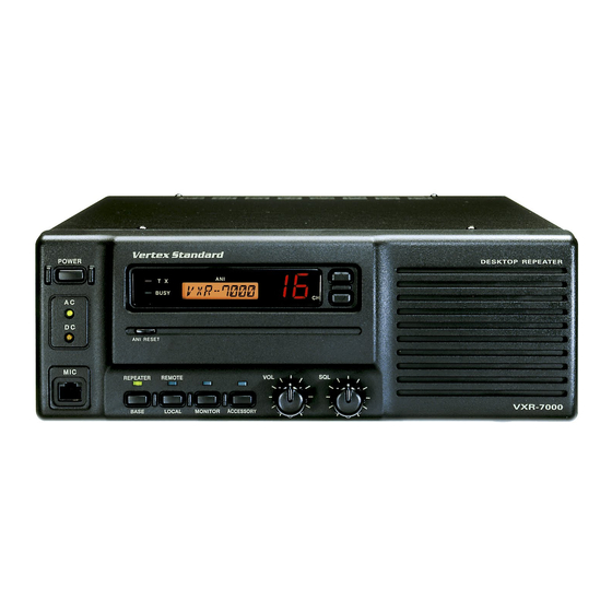
Desktop Repeater
VXR-7000
Service Manual
Introduction
This manual provides technical information necessary for servicing the VXR-7000 FM Land Mobile Repeater.
Servicing this equipment requires expertise in handling surface-mount chip components. Attempts by non-qualified per-
sons to service this equipment may result in permanent damage not covered by the warranty, and may be illegal in some
countries.
Two PCB layout diagrams are provided for each double-sided circuit board in the repeater. Each side of is referred to by
the type of the majority of components installed on that side ("leaded" or "chip-only"). In most cases one side has only
chip components, and the other has either a mixture of both chip and leaded components (trimmers, coils, electrolytic
capacitors, ICs, etc.), or leaded components only.
While we believe the technical information in this manual to be correct, VERTEX STANDARD assumes no liability for
damage that may occur as a result of typographical or other errors that may be present. Your cooperation in pointing out
any inconsistencies in the technical information would be appreciated.
After Lot. 78 of this transceiver is assembled using Pb (lead) free solder, based on the RoHS specification.
Only lead-free solder (Alloy Composition: Sn-3.0Ag-0.5Cu) should be used for repairs performed on this apparatus. The
solder stated above utilizes the alloy composition required for compliance with the lead-free specification, and any solder with
the above alloy composition may be used.
Operating Manual Reprint .......................... 2
CE27 Programming Software Instruction ................. 9
Specifications ............................................... 14
Block Diagram ............................................. 19
Interconnection Diagram ........................... 22
Circuit Description .................................... 23
Alignment ..................................................... 25
Board Unit (Schematics, Layouts & Parts)
PA Unit (Lot. 1~91) ................................................. 29
(VHF)
Important Note
Contents
Vertex Standard LMR, Inc.
© 2015 Vertex Standard LMR, Inc.
E136790P
PA-2 Unit (Lot. 92~) .......................................... 37
TX Unit ................................................................ 45
RX Unit ............................................................... 53
CNTL Unit .......................................................... 65
LPF Unit (Lot. 1~5) ............................................ 83
Display Unit ....................................................... 85
Key Unit .............................................................. 93
Filter Unit (50 W Type) ................................... 105
Filter-2 Unit (25 W Type) ............................... 113
SW Unit (25 W Type) ...................................... 119
VR Unit ............................................................. 121
SQL Unit ........................................................... 124
PS Unit .............................................................. 127
1
Advertisement
Table of Contents

Related Manuals for Vertex Standard VXR-7000


Summary of Contents for Vertex Standard VXR-7000
-
Page 1: Table Of Contents
ICs, etc.), or leaded components only. While we believe the technical information in this manual to be correct, VERTEX STANDARD assumes no liability for damage that may occur as a result of typographical or other errors that may be present. Your cooperation in pointing out any inconsistencies in the technical information would be appreciated. -
Page 2: Operating Manual Reprint
BASE/REPEATER Switch as High/Low power selection, as determined by your This switch toggles the operating mode between the Vertex Standard dealer. The LED above it glows green “REPEATER” mode and the “BASE” transceiver when this function is activated. For further details, mode. - Page 3 This DB-25 connector provides a data interface be- When operating from AC mains, a small trickle cur- tween the microprocessor in the VXR-7000 and pe- rent is present at these terminals to maintain battery ripheral devices (such as the VX-TRUNK Unit).
- Page 4 ACC Connector Port Pin 7: GND Chassis ground for all logic levels and power supply The VXR-7000 repeater is provided with a 25-pin DB- return. 25F female connector for interconnections to accesso- ries. Use a DB-25M 25-pin male connector to connect Pin 8: RSSI [Analog Output] accessories to the repeater.
- Page 5 This digital data sig- nal is injected after transmitter splatter filter stage. Pin 16 Pin 17 Pin 18 Pin 19 Channel ( D3 ) ( D2 ) ( D1 ) ( D0 ) VXR-7000 VHF Service Manual...
- Page 6 Operating Manual Reprint LINE Interface Port Installation The VXR-7000 is provided with an 8-pin modular jack Antenna Considerations for line interfacing applications. A Western Electric modu- ® Repeater operation without a duplexer requires that two lar-type RJ45 plug should be used to connect to this jack.
- Page 7 Never reapply AC power to the repeater with a discharged battery connected, as the DC startup current can dam- age the repeater and battery. While operating from a battery or DC supply, the repeater requires approximately 7 amperes at 12 Volts during trans- mit. VXR-7000 VHF Service Manual...
- Page 8 Switching Regulator Unit. also change the AC fuse on the FILTER Unit. Do not re- place with a slow-blow type fuse. FILTER Unit Switching Regulator Unit Figure 2 Figure 1 Switching Regulator Unit Figure 4 Figure 3 VXR-7000 VHF Service Manual...
-
Page 9: Ce27 Programming Software Instruction
Before creating the programming data for your Before connecting the VXR-7000 for programming, VXR-7000 via the CE27 programming software, turn off both the computer and the VXR-7000. Now con- upload the current factory hardware environ- nect the FIF-10A (or FIF-12) + CT-104A USB Program- ment data from the VXR-7000, using the [F5] ming Interface to the computer’s USB port and the VXR-... - Page 10 “off.” When this parameter is set to “on,” this function caus- es the VXR-7000 to send out a “blip” on the portable/ mobile radio is frequency each time the portable radio is unkeyed. This provides audible confirmation to the user that the VXR-7000 was able to receive the transmission from the portable.
- Page 11 TX Pwr: Transmitter Power Output Selection “Duplex” operation or “Simplex” operation. This parameter selects the desired power output from the VXR-7000 on the current channel. The available values Tx Freq.: Edit Transmit Frequency are HIGH and LOW. Use the [ 0 ] - [ 9 ] keys to enter the desired channel fre- Double-click the left mouse button to select “Hi”...
- Page 12 Operating Manual Reprint 1. Connect the VXR-7000’s TX antenna port to a watt- Duplexer Installation meter and dummy load (the duplexer must not be con- nected at this point). Connect any Vertex Standard Important Note microphone to the MIC jack, and place the BASE/ Be certain to observe the specifications for Fre- REPEATER switch in the “BASE”...
- Page 13 TX antenna jack of the repeater and ANT (center) bottom covers. jack of the duplexer. Top Side Bottom Side Figure 1 Bottom Side Figure 2 Figure 3 VXR-7000 VHF Service Manual...
-
Page 14: Specifications
±5.0 kHz (25 kHz spacing), ±2.5 kHz (12.5 kHz spacing) Maximum Deviation: 16K0G3E/8K50G3E Modulation Type: Less than 2.5 % @ 1 kHz Audio Distortion: < –36 dBm @ <1 GHz, <–30 dBm @ >1 GHz Spurious Emissions: Specifications subject to change without notice or obligation. VXR-7000 VHF Service Manual... -
Page 15: Exploded View & Miscellaneous Parts
TOOTHED LOCK WASHER OW4NI Ⓔ M4090066 RA0181200 SPEAKER Non-designated parts are available only as part of a designated assembly. HOLDER (MJ) SQL Unit RA0065800 RUBBER HOLDER (SP) Ⓘ VOL Unit RA0180700 RA0180500 PUSH KNOB (4pcs) VOLUME KNOB VXR-7000 VHF Service Manual... - Page 16 TOOTHED LOCK WASHER OW4NI CONNECTOR RA0181200 SPEAKER SQL Unit HOLDER (MJ) Non-designated parts are available only as part of a designated assembly. RA0065800 RUBBER HOLDER (SP) Ⓘ VOL Unit RA0180500 RA0180700 VOLUME KNOB PUSH KNOB (4pcs) VXR-7000 VHF Service Manual...
- Page 17 Heat sink PA-2 ASSY CS1861001 for 25 W CS1861002 for 50 W Main Heat Sink Plate (No Part # and impossible to purchase this part only) Rubber Spacer Heat Sink Plate Screws M2.6X5 RA0766400 RA0766900 U32450001 VXR-7000 VHF Service Manual...
- Page 18 Non-designated parts are available only as part of a designated assembly. FOOT (4pcs) TX Unit P1091073 Ⓔ M4090066 CONNECTOR RA0181200 SPEAKER SQL Unit HOLDER (MJ) RA0065800 RUBBER HOLDER (SP) Ⓘ VOL Unit RA0180500 RA0180700 VOLUME KNOB PUSH KNOB (4pcs) VXR-7000 VHF Service Manual...
-
Page 19: Block Diagram
Block Diagram VXR-7000 VHF Service Manual... - Page 20 Block Diagram VXR-7000 VHF Service Manual...
- Page 21 Block Diagram VXR-7000 VHF Service Manual...
-
Page 22: Interconnection Diagram
Interconnection Diagram VXR-7000 VHF Service Manual... -
Page 23: Circuit Description
The RX VCO, consisting of FET Q3007 and varactor di- audio signal subsequently passes through the a 3-section active odes D3005, D3006, D3009, and D3010, oscillates between low pass filter consisting of Q4019-1/-2/-3 (NJM2902M) and 114.6 MHz and 152.6 MHz according to the programmed re- VXR-7000 VHF Service Manual... - Page 24 Q4021 (NJM2902M) to the pre- (2SC3357) and RF power module IC Q1502 (PF0310A), then emphasis network at Q4018-1, where the signal is processed in the same manner as previously described. VXR-7000 VHF Service Manual...
-
Page 25: Alignment
Alignment Required Test Equipment The VXR-7000 is carefully aligned at the factory for the specified performance across the entire operating fre- RF Signal Generator with calibrated output level at 200 quency range. Realignment should therefore not be nec- Deviation Meter (linear detector) essary except in the event of a component failure. - Page 26 0 (00h) ~ 255 (FFh) TX Power Level (Low) 0 (00h) ~ 255 (FFh) Maximum Deviation 0 (00h) ~ 255 (FFh) CTCSS Deviation 0 (00h) ~ 255 (FFh) DCS Deviation 0 (00h) ~ 255 (FFh) J2001 TX Unit Alignment Points VXR-7000 VHF Service Manual...
- Page 27 Unit. Select the Center channel, adjust TC3001 (on the RX Unit), if necessary, so that the frequency counter read- ing is within ±100 Hz of the programmed Center chan- nel frequency. RX Unit Alignment Points VXR-7000 VHF Service Manual...
- Page 28 AF generator output level to –10 dBm, at a frequency of 1 kHz. Key the repeater, and adjust VR4003 (on the CNTL Unit) so that the deviation meter reading (TX devia- tion) is 3.0 kHz (±0.1 kHz) deviation. CNTL Unit Alignment Points VXR-7000 VHF Service Manual...
-
Page 29: Pa Unit (Lot. 1~91)
PA Unit (Lot. 1~91: Replaced by PA-2 Unit) Circuit Diagram VXR-7000 VHF Service Manual... - Page 30 PA Unit (Lot. 1~91: Replaced by PA-2 Unit) Parts Layout Side A 2SC5125 PF0314 (TYP C) (Q1507) PF0313 (TYP A: Lot. 7~) (Q1502) VXR-7000 VHF Service Manual...
- Page 31 PA Unit (Lot. 1~91: Replaced by PA-2 Unit) Side B TA75S01F (SA) NJM78L09UA (8H) UN5213 (8C) 2SB1122S (BE) 2SC3357 (RK) 2SC4116GR (LG) 1SS319 (A4) MA143 (MC) (Q1509) (Q1508) (Q1506) (Q1503, 1505) (Q1501) (Q1504) (D1503, 1504) (D1502) RN739F (5F) (D1501) VXR-7000 VHF Service Manual...
- Page 32 PA Unit (Lot. 1~91: Replaced by PA-2 Unit) Note: VXR-7000 VHF Service Manual...
- Page 33 AL.ELECTRO.CAP. 1000uF RJ3-25V102MI5# K40149041 C 1535 CHIP CAP. 0.001uF 500V W5R GRM42-6W5R102K500PT K22271801 C 1536 CHIP CAP. 0.01uF 200V X7R GRM42-6X7R103K200PT K22231802 C 1537 CHIP CAP. W5R CM32W5R105K25AT K22145801 1-18 C 1537 CHIP CAP. GRM32RB11H105KA01L K22175801 VXR-7000 VHF Service Manual...
- Page 34 D 1501 DIODE RN739F T106 G2070626 D 1502 DIODE MA143-(TX) G2070536 D 1503 DIODE 1SS319(TE85R.F) G2070080 D 1504 DIODE 1SS319(TE85R.F) G2070080 FB1501 M.RFC FBA03VA450AB-00 L1190389 FB1502 FERRITE BEADS 4A2 RI3X3-1 L9190001 FB1503 FERRITE BEADS 4A2 RI3X3-1 L9190001 VXR-7000 VHF Service Manual...
- Page 35 RMC1/16 102JATP J24185102 R 1516 CHIP RES. 2.2k 1/16W RMC1/16 222JATP J24185222 R 1517 CHIP RES. 1/16W RMC1/16 103JATP J24185103 R 1519 CHIP RES. 1/16W RMC1/16 102JATP J24185102 R 1520 CHIP RES. 1/16W RMC1/16 333JATP J24185333 VXR-7000 VHF Service Manual...
- Page 36 NYLON CLAMP PLT-1M BK-1 S3000022 VERS: A, EIA (CE) NYLON CLAMP PLT-1M BK-1 S3000022 VERS: C, EIA (CE) NYLON CLAMP PLT-1M BK-1 S3000022 VERS: A, EIA (CE) NYLON CLAMP PLT-1M BK-1 S3000022 VERS: C, EIA (CE) VXR-7000 VHF Service Manual...
-
Page 37: Unit (Lot. 92~)
RESISTOR VALUES ARE IN . 1/16W ; CAPACITOR VALUES ARE IN μF. 50V ; (T) CAPACITOR VALUES ARE TANTALUM ; ELECTOROLYTIC CAPACITORS ARE IN μF. 16V ; INDUCTOR VALUES ARE IN H ; COIL VALUES ARE IN H ; UNLESS OTHERWISE NOTED. VXR-7000 VHF Service Manual... - Page 38 PA-2 Unit (Lot. 92~) Note VXR-7000 VHF Service Manual...
- Page 39 PA-2 Unit (Lot. 92~) Parts Layout Side A S-AV32 FMG2 (26) NJM78L09UA (8H) DTC144E (26) (Q7007) (Q7004) (Q7008) (Q7006) LM2904PWR 2SC3357 (RK) 2SA1179M6 (M6) RN739F (5F) (Q7009) (Q7001) (Q7005) (D7001, 7005) HSM88AS (C1) D7003, 7004) VXR-7000 VHF Service Manual...
- Page 40 PA-2 Unit (Lot. 92~) Parts Layout Side B VXR-7000 VHF Service Manual...
- Page 41 GRM188B11H102KA01D K22174821 C 7056 CHIP CAP. 100pF GRM1882C1H101JA01D K22174235 C 7057 CHIP TA.CAP. TEESVA1E105M8R K78140013 C 7058 CHIP CAP. 0.01uF GRM188B11H103KA01D K22174823 C 7059 CHIP CAP. 0.01uF GRM188B11H103KA01D K22174823 C 7060 CHIP TA.CAP. 10uF TEESVB21C106M8R K78120025 VXR-7000 VHF Service Manual...
- Page 42 0.068uH ELJ-RE68NJF3 L1690724 L 7010 COIL 0.039uH AS1006-39NK L0022547 VERS. C, 50W 132- Q 7001 TRANSISTOR 2SC3357-T2 RF G3333577F Q 7004 TRANSISTOR FMG2 T148 G3070015 Q 7005 TRANSISTOR 2SA1179N6-CPA-TB G3111797F Q 7006 TRANSISTOR DTC144EUA T106 G3070041 VXR-7000 VHF Service Manual...
- Page 43 PLT-1M BK-1 S3000022 NYLON CLAMP PLT-1M BK-1 S3000022 GROUND PLATE RA069650A GROUND PLATE RA069650A 166- GROUND PLATE RA069650A 166- GROUND PLATE RA069650A 166- GROUND PLATE RA069650A 166- GROUND PLATE RA069650A 166- TERMINAL B4 AG M3 Q6000114 166- VXR-7000 VHF Service Manual...
- Page 44 PA-2 Unit (Lot. 92~) Note: VXR-7000 VHF Service Manual...
-
Page 45: Tx Unit
TX Unit (Lot. 1~5) Circuit Diagram VXR-7000 VHF Service Manual... - Page 46 2SA1179 (M6) 2SC4116GR (LG) UN5215 (8E) XN1213 (9L) RN739F (5F) MA143 (MC) (Q2001) (Q2012) (Q2005) (Q2010) (Q2014, 2016) (Q2013, 2017) (Q2002, 2006, 2009) (Q2004) (Q2011, 2015) (D2007, 2008) (D2009, 2010) 2SA1586Y (SY) 2SC5226 (R22) (Q2003, 2007) (Q2008) VXR-7000 VHF Service Manual...
- Page 47 TX Unit (Lot. 6~) Circuit Diagram VXR-7000 VHF Service Manual...
- Page 48 2SA1179 (M6) 2SC4116GR (LG) UN5215 (8E) XN1213 (9L) RN739F (5F) MA143 (MC) (Q2001) (Q2012) (Q2005) (Q2010) (Q2014, 2016) (Q2013, 2017) (Q2002, 2006, 2009) (Q2004) (Q2011, 2015) (D2007, 2008) (D2009, 2010) 2SA1586Y (SY) 2SC5226 (R22) (Q2003, 2007) (Q2008) VXR-7000 VHF Service Manual...
- Page 49 K22174821 C 2053 CHIP TA.CAP. 10uF TEESVB21C106M8R K78120025 C 2054 CHIP CAP. 0.001uF GRM188B11H102KA01D K22174821 C 2055 CHIP CAP. 470pF GRM1882C1H471JA01D K22174249 C 2056 CHIP CAP. 0.001uF GRM188B11H102KA01D K22174821 C 2057 CHIP CAP. 0.001uF GRM188B11H102KA01D K22174821 VXR-7000 VHF Service Manual...
- Page 50 J24185102 R 2004 CHIP RES. 1.8k 1/16W RMC1/16 182JATP J24185182 R 2005 CHIP RES. 1.8k 1/16W RMC1/16 182JATP J24185182 R 2006 CHIP RES. 1/16W RMC1/16 470JATP J24185470 R 2007 CHIP RES. 4.7k 1/16W RMC1/16 472JATP J24185472 VXR-7000 VHF Service Manual...
- Page 51 1-93 R 2060 CHIP RES. 1/16W RMC1/16 180JATP J24185180 VERS. A, Ex. EIA/CE R 2060 CHIP RES. 1/16W RMC1/16 180JATP J24185180 VERS. C, Ex. EIA/CE R 2060 CHIP RES. 1/16W RMC1/16 180JATP J24185180 VERS. A, EIA/CE VXR-7000 VHF Service Manual...
- Page 52 J24185000 TC2001 TRIMMER CAP. 10pF ECR-JA010A11X K91000227 1-128 TC2001 TRIMMER CAP. 10pF TZB4Z100AA10R00 K91000285 149- TH2001 THERMISTOR NTCG203SH223JT G9090106 TH2002 THERMISTOR NTCG203NH153JT G9090105 X 2001 XTAL TOP-B 14.4MHz 14.4MHZ H0103221 SHIELD CASE RA0014300 SHIELD CASE R0151950 VXR-7000 VHF Service Manual...
-
Page 53: Rx Unit
RX Unit (Lot. 1~5) Circuit Diagram VXR-7000 VHF Service Manual... - Page 54 TA78L05F (AE) UN5215 (8E) 2SA1586Y (SY) 2SC2620 (QB) 2SK508 (K52) 2SC3357 (RK) MA143 (MC) (Q3001) (Q3012) (D3014) (Q3021) (Q3004) (Q3003) (Q3016) (Q3007) (Q3008, 3011) (D3011, 3018, 3019) 2SC4116GR (LG) RN739F (5F) (Q3002, 3014) (D3003) 2SC5226 (R22) (Q3009) VXR-7000 VHF Service Manual...
- Page 55 RX Unit (Lot. 1~5) Side B XN1213 (9L) 2SB1122S (BE) 2SA1586Y (SY) 2SC2812 (L6) MA143 (MC) MA142WK (MU) HZM5.6NB2 (562) (D3001, 3021) (Q3015, 3020, 3022) (Q3018) (Q3006) (Q3013) (D3015, 3016) (D3017) 2SC4116GR (LG) (Q3005, 3010) VXR-7000 VHF Service Manual...
- Page 56 RX Unit (Lot. 6~) Circuit Diagram VXR-7000 VHF Service Manual...
- Page 57 TA78L05F (AE) UN5215 (8E) 2SA1586Y (SY) 2SC2620 (QB) 2SK508 (K52) 2SC3357 (RK) MA143 (MC) (Q3001) (Q3012) (D3014) (Q3021) (Q3004) (Q3003) (Q3016) (Q3007) (Q3008, 3011) (D3011, 3018, 3019) 2SC4116GR (LG) RN739F (5F) (Q3002, 3014) (D3003) 2SC5226 (R22) (Q3009) VXR-7000 VHF Service Manual...
- Page 58 RX Unit (Lot. 6~) Side B XN1213 (9L) 2SB1122S (BE) 2SA1586Y (SY) 2SC2812 (L6) MA143 (MC) MA142WK (MU) HZM5.6NB2 (562) (D3001, 3021) (Q3015, 3020, 3022) (Q3018) (Q3006) (Q3013) (D3015, 3016) (D3017) 2SC4116GR (LG) (Q3005, 3010) VXR-7000 VHF Service Manual...
- Page 59 C 3047 CHIP CAP. 0.001uF GRM188B11H102KA01D K22174821 1-10 C 3047 CHIP CAP. 0.01uF GRM39B103M25PT K22144802 C 3048 CHIP CAP. GRM1884C1H2R0CZ01D K22174203 C 3049 CHIP CAP. GRM1882C1H9R0DZ01D K22174210 C 3049 CHIP CAP. 22pF GRM1882C1H220JA01D K22174219 VERSION A VXR-7000 VHF Service Manual...
- Page 60 K22174241 C 3104 CHIP CAP. 0.1uF GRM188B11C104KA01D K22124805 C 3105 CHIP CAP. 0.001uF GRM188B11H102KA01D K22174821 C 3106 CHIP CAP. 0.001uF GRM188B11H102KA01D K22174821 C 3107 CHIP CAP. 0.001uF GRM188B11H102KA01D K22174821 C 3108 CHIP CAP. 0.1uF GRM188B11C104KA01D K22124805 VXR-7000 VHF Service Manual...
- Page 61 GRN 35 2/2 T50503500 L 3001 M.RFC 10uH LK1608 100K-T L1690689 L 3002 CHIP COIL 0.1uH C2520C-R10J L1690544 L 3002 CHIP COIL 0.12uH C2520C-R12J L1690545 VERSION A L 3002 CHIP COIL 0.1uH C2520C-R10J L1690544 VERSION C VXR-7000 VHF Service Manual...
- Page 62 RMC1/16 104JATP J24185104 R 3017 CHIP RES. 1/16W RMC1/16 473JATP J24185473 R 3018 CHIP RES. 1/16W RMC1/16 103JATP J24185103 R 3019 CHIP RES. 1/16W RMC1/16 473JATP J24185473 R 3020 CHIP RES. 4.7k 1/16W RMC1/16 472JATP J24185472 VXR-7000 VHF Service Manual...
- Page 63 J24183104 R 3101 CHIP RES. 8.2k 1/16W RMC1/16 822FTP J24183822 R 3102 CHIP RES. 1/16W RMC1/16 473FTP J24183473 R 3103 CHIP RES. 3.9k 1/16W RMC1/16 392FTP J24183392 R 3106 CHIP RES. 4.7k 1/16W RMC1/16 472JATP J24185472 VXR-7000 VHF Service Manual...
- Page 64 XTAL TOP-B 14.4MHz 14.4MHZ H0103221 X 3002 XTAL LP-5.0S.2S 20.945MHz 20.945MHZ H0103169 XF3001 XTAL FILTER 21M10B1 H1102314 XF3002 XTAL FILTER 21M10B1 H1102314 SHIELD CASE RA0014300 SHIELD CASE R0151950 SHIELD CASE RA0014200 NYLON CLAMP PLT-1M BK-1 S3000022 VXR-7000 VHF Service Manual...
-
Page 65: Cntl Unit
CNTL Unit (Lot. 1~5) Circuit Diagram VXR-7000 VHF Service Manual... - Page 66 FMG2 (G2) DTC323TK (H02) (Q4023, 4035, 4044) (Q4028, 4032) (Q4036, 4038) TLP181 2SC4116GR (LG) 2SA1586Y (SY) (Q4041, 4042) (Q4027) (Q4007) DA204K (K) Side A (D4006, 4009, 4012, 4016, 4019, 4020, 4022, 4023) MA143 (MC) (D4036, 4037) VXR-7000 VHF Service Manual...
- Page 67 AN8005M (Q4004) (Q4006, 4009, 4010, 4011) DTC144EK (26) DTC323TK (H02) (Q4003) (Q4026, 4037) 2SC4116GR (LG) (Q4013) DA204K (K) 1SS184 (B3) (D4001, 4002, 4003, (D4025, 4026) 4004, 4005, 4017, 4018, 4021, 4024) HZM7C (24) (D4008) Side B VXR-7000 VHF Service Manual...
- Page 68 CNTL Unit (Lot. 6~) Circuit Diagram VXR-7000 VHF Service Manual...
- Page 69 FMG2 (G2) DTC323TK (H02) (Q4023, 4035, 4044) (Q4028, 4032) (Q4036, 4038) TLP181 2SC4116GR (LG) 2SA1586Y (SY) (Q4041, 4042) (Q4027) (Q4007) Side A DA204K (K) (D4006, 4009, 4012, 4016, 4019, 4020, 4022, 4023) MA143 (MC) (D4036, 4037) VXR-7000 VHF Service Manual...
- Page 70 AN8005M (Q4004) (Q4006, 4009, 4010, 4011) DTC144EK (26) DTC323TK (H02) (Q4003) (Q4026, 4037) 2SC4116GR (LG) (Q4013) DA204K (K) 1SS184 (B3) (D4001, 4002, 4003, (D4025, 4026) 4004, 4005, 4017, 4018, 4021, 4024, 4040) HZM7.5NB2 (D4008) Side B VXR-7000 VHF Service Manual...
- Page 71 K22124805 C 4061 CHIP CAP. 100pF GRM1882C1H101JA01D K22174235 C 4062 CHIP CAP. 100pF GRM1882C1H101JA01D K22174235 C 4063 CHIP CAP. 100pF GRM1882C1H101JA01D K22174235 C 4064 CHIP CAP. 100pF GRM1882C1H101JA01D K22174235 C 4065 CHIP CAP. 100pF GRM1882C1H101JA01D K22174235 VXR-7000 VHF Service Manual...
- Page 72 GRM1882C1H101JA01D K22174235 C 4135 CHIP CAP. 100pF GRM1882C1H101JA01D K22174235 C 4136 CHIP CAP. 0.1uF GRM188B11C104KA01D K22124805 C 4137 CHIP CAP. 0.001uF GRM188B11H102KA01D K22174821 C 4138 CHIP CAP. 0.0047uF GRM188B11H472KA01D K22174817 C 4139 CHIP TA.CAP. TEESVA1E105M8R K78140013 VXR-7000 VHF Service Manual...
- Page 73 K22174227 C 4201 CHIP CAP. 0.01uF GRM39B103K25PT K22144803 C 4202 CHIP CAP. 0.001uF GRM188B11H102KA01D K22174821 C 4203 CHIP CAP. 0.01uF GRM39B103K25PT K22144803 C 4204 CHIP CAP. 0.001uF GRM188B11H102KA01D K22174821 C 4205 CHIP CAP. 0.01uF GRM39B103K25PT K22144803 VXR-7000 VHF Service Manual...
- Page 74 C 4273 CHIP CAP. 0.022uF GRM39B223K25PT K22144807 C 4274 CHIP CAP. 0.056uF GRM188B11C563KA01D K22124807 C 4275 CHIP CAP. 0.0027uF ECJ1VB1H272K K22179619 6-162 C 4275 CHIP CAP. 0.0027uF GRM188B11H272KA01D K22174814 163- C 4276 CHIP TA.CAP. 10uF TEESVA1A106M8R K78100028 VXR-7000 VHF Service Manual...
- Page 75 P0090613 J 4005 CONNECTOR SB20-06WS P0090613 J 4006 CONNECTOR SB20-15WS P0091093 J 4007 CONNECTOR SB20-14WS P0090656 J 4008 CONNECTOR SB20-13WS P0090620 J 4009 CONNECTOR B8B-PH-K-S(LF)(SN) P0090402 J 4010 CONNECTOR SB20-03WS P0090610 J 4011 CONNECTOR SB20-02WS P0090609 VXR-7000 VHF Service Manual...
- Page 76 Q 4033 NJM2902V-TE1 G1091679 Q 4034 NJM2902M-TE1 G1093092 Q 4034 NJM2902V-TE1 G1091679 Q 4035 TRANSISTOR DTC144EK T146 G3070033 Q 4036 TRANSISTOR DTC323TK T146 G3070042 Q 4037 TRANSISTOR DTC323TK T146 G3070042 Q 4038 TRANSISTOR DTC323TK T146 G3070042 VXR-7000 VHF Service Manual...
- Page 77 1/16W RMC1/16 473JATP J24185473 R 4066 CHIP RES. 1/16W RMC1/16 103JATP J24185103 R 4067 CHIP RES. 1/16W RMC1/16 473JATP J24185473 R 4068 CHIP RES. 1/16W RMC1/16 471JATP J24185471 R 4069 CHIP RES. 1/16W RMC1/16 471JATP J24185471 VXR-7000 VHF Service Manual...
- Page 78 CHIP RES. 150k 1/16W RMC1/16 154JATP J24185154 R 4142 CHIP RES. 100k 1/16W RMC1/16 104JATP J24185104 1-164 R 4142 CHIP RES. 120k 1/16W RMC1/16 124JATP J24185124 165- R 4143 CHIP RES. 100k 1/16W RMC1/16 104JATP J24185104 VXR-7000 VHF Service Manual...
- Page 79 RMC1/16 103JATP J24185103 R 4210 CHIP RES. 1/16W RMC1/16 393JATP J24185393 R 4211 CHIP RES. 1/16W RMC1/16 102JATP J24185102 R 4212 CHIP RES. 6.8k 1/16W RMC1/16 682JATP J24185682 R 4214 CHIP RES. 220k 1/16W RMC1/16 224JATP J24185224 VXR-7000 VHF Service Manual...
- Page 80 J24185104 R 4280 CHIP RES. 100k 1/16W RMC1/16 104JATP J24185104 R 4281 CHIP RES. 3.9k 1/16W RMC1/16 392JATP J24185392 R 4282 CHIP RES. 100k 1/16W RMC1/16 104JATP J24185104 R 4283 CHIP RES. 1/16W RMC1/16 561JATP J24185561 VXR-7000 VHF Service Manual...
- Page 81 EVN-5ESX50B14 J51811103 1-149 VR4002 POT. EVM3VSX50B14 J51843103 150- VR4003 POT. EVN-5ESX50B14 J51811103 1-149 VR4003 POT. EVM3VSX50B14 J51843103 150- X 4001 XTAL HC-49/S3 16MHz 16.000MHZ H0103174 X 4002 XTAL HC-49/4H 4.194304MHz 4.194304MHZ H0103081 HEAT SINK SP143K S5000217 VXR-7000 VHF Service Manual...
- Page 82 CNTL Unit Note: VXR-7000 VHF Service Manual...
-
Page 83: Lpf Unit (Lot. 1~5)
LPF Unit (Lot. 1~5) Circuit Diagram Parts Layout Side A Side B NJM2902M DA204K (K) (Q4901, 4902) (D4901) VXR-7000 VHF Service Manual... - Page 84 J24185124 R 4925 CHIP RES. 120k 1/16W RMC1/16 124JATP J24185124 R 4927 CHIP RES. 120k 1/16W RMC1/16 124JATP J24185124 R 4928 CHIP RES. 120k 1/16W RMC1/16 124JATP J24185124 R 4930 CHIP RES. 1/16W RMC1/16 000JATP J24185000 VXR-7000 VHF Service Manual...
-
Page 85: Display Unit
Display Unit (Lot. 1~123) Circuit Diagram VXR-7000 VHF Service Manual... - Page 86 XN1213 (9L) (Q5003) (Q5005) (Q5002, 5004) Side A DTC144EK (26) MA143 (MC) (Q5006, 5009) (D5003, 5005, 5006, 5007, 5008, 5009, 5010, 5011, 5014, 5015, 5016, 5017, 5018) LCD Display Segmentation Diagram Side B LCD Display Backplane Diagram VXR-7000 VHF Service Manual...
- Page 87 Display Unit (Lot. 124~) Circuit Diagram VXR-7000 VHF Service Manual...
- Page 88 5014, 5015, 5018, 5019, 5020, 5021) Side A 2SC4617 (BR) DAN217U (A7) (Q5004) (D5003, 5004, 5005, 5006, 5007, 5008, 5009, 5010, 5011, 5014, 5015, 5016, 5017, 5018) LCD Display Segmentation Diagram Side B LCD Display Backplane Diagram VXR-7000 VHF Service Manual...
- Page 89 DAN217U T106 G2071236 124- D 5019 DIODE MA729-(TX) G2070320 124-173 D 5019 DIODE DB2J31300L G2071338 174- DS5001 LCD TTR3165UPFDCW G6090134 1-74 DS5001 LCD A15A012X G6090159 75-185 DS5001 LCD GHG4346ST01 G6090226 186- DS5002 LED NAA261-B G2090745 1-123 VXR-7000 VHF Service Manual...
- Page 90 R 5022 CHIP RES. 1/16W RMC1/16 331JATP J24185331 124- R 5023 CHIP RES. 1/16W RMC1/16 331JATP J24185331 124- R 5024 CHIP RES. 1/16W RMC1/16 331JATP J24185331 124- R 5025 CHIP RES. 1/16W RMC1/16 000JATP J24185000 124- VXR-7000 VHF Service Manual...
- Page 91 1-123 X 5001 XTAL U3B 7.3728MHz 7.3728MHZ H0103280 124- LCD HOLDER RA0014900 LIGHT GUIDE RA0013200 REFLECTOR SHEET RA0013500 DIFFUSER SHEET RA0013600 INTER CONNECTOR RA0013700 SPONGE RUBBER R7130200 LED SPACER LH-5-4 S6000237 LED SPACER LH-5-2 S6000235 1-123 VXR-7000 VHF Service Manual...
- Page 92 Display Unit Note: VXR-7000 VHF Service Manual...
-
Page 93: Key Unit
KEY Unit (Lot. 1~5) Circuit Diagram... - Page 94 KEY Unit (Lot. 1~5) Parts Layout BU4094BCFV (Q5503) Side A...
- Page 95 KEY Unit (Lot. 1~5) XN1213 (9L) (Q5502, 5504, 5505) DTC323TK (H02) (Q5501) DTC144EK (26) (Q5506) Side B...
- Page 96 KEY Unit (Lot. 6~123) Circuit Diagram...
- Page 97 KEY Unit (Lot. 6~123) Parts Layout BU4094BCFV (Q5503) Side A...
- Page 98 KEY Unit (Lot. 6~123) XN1213 (9L) (Q5502, 5504, 5505) DTC323TK (H02) (Q5501) DTC144EK (26) (Q5506) Side B...
- Page 99 KEY Unit (Lot. 124~) Circuit Diagram...
- Page 100 KEY Unit (Lot. 124~) Parts Layout BU4094BCFV (Q5503) Side A...
- Page 101 KEY Unit (Lot. 124~) XN1213 (9L) (Q5502, 5504, 5505) DTC323TK (H02) (Q5501) DTC144EK (26) (Q5506) Side B...
- Page 102 KEY Unit Note:...
- Page 103 S 5502 PUSH SWITCH SPPH110300 N4090142 S 5503 PUSH SWITCH SPPH110300 N4090142 S 5504 PUSH SWITCH SPPH110300 N4090142 S 5505 PUSH SWITCH SPPH110300 N4090142 LED SPACER LH-3-13 S6000350 LED SPACER LH-5-14 S6000387 LED SPACER LH-5-10 S6000243 VXR-7000 VHF Service Manual...
- Page 104 Key Unit Note: VXR-7000 VHF Service Manual...
-
Page 105: Filter Unit (50 W Type)
FILTER Unit (Lot. 1~5) Circuit Diagram VXR-7000 VHF Service Manual... - Page 106 FILTER Unit (Lot. 1~5) Parts Layout Side A NJM2904M XN1213 (9L) UN5213 (8C) IMX1 (X1) (Q6006) (Q6003) (Q6002) (Q6007) 2SA1179 (M6) 2SC2812 (L6) DAN202K (N) (Q6001) (Q6004, 6008) (D6002, 6005) VXR-7000 VHF Service Manual...
- Page 107 FILTER Unit (Lot. 1~5) Side B VXR-7000 VHF Service Manual...
- Page 108 FILTER Unit (Lot. 6~) Circuit Diagram VXR-7000 VHF Service Manual...
- Page 109 FILTER Unit (Lot. 6~) Parts Layout Side A NJM2904M XN1213 (9L) UN5213 (8C) IMX1 (X1) (Q6006) (Q6003) (Q6002) (Q6007) 2SA1179 (M6) 2SC2812 (L6) DAN202K (N) (Q6001) (Q6004, 6008) (D6002, 6005) VXR-7000 VHF Service Manual...
- Page 110 FILETR Unit (Lot. 6~) Side B VXR-7000 VHF Service Manual...
- Page 111 1/16W RMC1/16 224JATP J24185224 R 6004 CHIP RES. 1/16W RMC1/16 103JATP J24185103 R 6005 CHIP RES. 1/10W RMC1/10T 220J J24205220 R 6006 CHIP RES. 1/16W RMC1/16 223JATP J24185223 R 6007 CHIP RES. 1/16W RMC1/16 223JATP J24185223 VXR-7000 VHF Service Manual...
- Page 112 DC12V ACP131 DC12V M1190152 RL6003 RELAY DC12V ACP131 DC12V M1190152 T 6001 TOROIDAL COIL D12A RI16X8X8 L0022119 1-18 T 6002 TOROIDAL COIL SC-05-100 L2190031 USA/NA 1-18 T 6003 TOROIDAL COIL D12A RI16X8X8 L0022119 1-18 RUBBER RA0217100 VXR-7000 VHF Service Manual...
-
Page 113: Filter-2 Unit (25W Type)
Filter-2 Unit (25W Type) Circuit Diagram NOTE: RESISTOR VALUES ARE IN . 1/16W ; CAPACITOR VALUES ARE IN μF. 50V ; (T) CAPACITOR VALUES ARE TANTALUM ; ELECTOROLYTIC CAPACITORS ARE IN μF. 16V ; INDUCTOR VALUES ARE IN H ; COIL VALUES ARE IN H ;... - Page 114 Filter-2 Unit (25W Type) Note:...
- Page 115 Filter-2 Unit (25W Type) Parts Layout Side A 2SA1179 (M6) 2SC2812 (L6) IMX1 (X1) UN5213 (8C) XN1213 (9L) DAN202K (N) (Q6001) (Q6004, 6008) (Q6007) (Q6002) (Q6003) (D6002, 6005)
- Page 116 Filter-2 Unit (25W Type) Side B...
- Page 117 RMC1/16 563JATP J24185563 R 6024 CHIP RES. 1/16W RMC1/16 223JATP J24185223 R 6025 CHIP RES. 1/16W RMC1/16 181JATP J24185181 R 6026 CHIP RES. 3.3k 1/16W RMC1/16 332JATP J24185332 R 6027 CHIP RES. 1.8k 1/16W RMC1/16 182JATP J24185182 VXR-7000 VHF Service Manual...
- Page 118 CHIP RES. 2.2k 1/16W RMC1/16 222JATP J24185222 R 6030 CHIP RES. 1/16W RMC1/16 223JATP J24185223 R 6031 CHIP RES. 1/16W RMC1/16 223JATP J24185223 RL6001 RELAY DC12V ACP131 DC12V M1190152 RL6003 RELAY DC12V ACP131 DC12V M1190152 RUBBER RA0217100 VXR-7000 VHF Service Manual...
-
Page 119: Sw Unit (25 W Type)
A1367+ T9206794 JP6502 WIRE ASSY WHT 340 SRA/<7> T9318166 JP6503 WIRE ASSY BLK 330 SRA/<7> T9318167 JP6504 WIRE ASSY BRN 320 SRA/<7> T9318168 JP6505 WIRE ASSY GRA 330 SRA/<7> T9318169 S 6501 PUSH SWITCH SDDFE30100 N4090147 VXR-7000 VHF Service Manual... - Page 120 SW Unit (25 W Type) Note: VXR-7000 VHF Service Manual...
-
Page 121: Vr Unit
VR Unit (Lot. 1~5) Circuit Diagram Parts Layout Side A Side B VXR-7000 VHF Service Manual... - Page 122 VR Unit (Lot. 6~123) Circuit Diagram Parts Layout Side A Side B VXR-7000 VHF Service Manual...
- Page 123 VR Unit (Lot. 124~) Circuit Diagram Parts Layout Side A Side B Parts List REF. DESCRIPTION VALUE TOL. MFR’S DESIG VXSTD P/N VERS. LOT. SIDE LAYADR PCB with Components CS2349101 VR5901 POT. RK0971110 10KA(L=25) J60800241 VXR-7000 VHF Service Manual...
-
Page 124: Sql Unit
SQL Unit (Lot. 1~5) Circuit Diagram Parts Layout Side A Side B VXR-7000 VHF Service Manual... - Page 125 SQL Unit (Lot. 6~123) Circuit Diagram Parts Layout Side A Side B VXR-7000 VHF Service Manual...
- Page 126 Side A Side B Parts List REF. DESCRIPTION VALUE TOL. MFR’S DESIG VXSTD P/N VERS. LOT. SIDE LAYADR PCB with Components CS2320101 JP5951 WIRE ASSY A1367+ T9206798A JP5951 WIRE ASSY A1367+ T9206811 VR5951 POT. RK0971110 10KB(L=25) J60800242 VXR-7000 VHF Service Manual...
-
Page 127: Ps Unit
2200p R 38 D 28 H Z5C 1 470K 1/ 2W R 35 C 35 C 34 0. 1u 0. 47u A C 250V D 27 1S S 270A C N 1 A C I N VXR-7000 VHF Service Manual... - Page 128 PS Unit Parts Layout S-80745AN (DI) NJM2904L (IC0001) 2PA1015 (IC0021) 2SC4166Q 2SK1017 BT138D-600 (Q0021) (Q0004) DTC114ESA (Q0002, 0003) (Q0001) 2PC1815 2SC3246 (Q0005) (Q0022) (Q0006) VXR-7000 VHF Service Manual...
- Page 129 J01279001 R 0002 METAL FILM RES. ERG-1SJ101 J22305101 R 0003 THERMISTOR 8D-13 G9090130 R 0004 CARBON FILM RES. 1/6W RD16PJ J01225102 R 0005 METAL FILM RES. ERG-1SJ101 J22305101 R 0006 METAL FILM RES. 100k ERG-1SJ104 J22309049 VXR-7000 VHF Service Manual...
- Page 130 FP2017A-614 S8001788 FITTING B FP2017A-615 S8001789 THERMAL CONDUCTER FP2017A-701 S8001790 THERMAL CONDUCTER FB419 S8001781 THERMAL CONDUCTER (4pcs) TC45A-(CP-T0-3P) S8001782 THERMAL CONDUCTER TC45A-(CP-T0-220) S8001783 FITTING (5pcs) FR336A S8001784 FITTING FR309A S8000030 SPACER (5pcs) S8001794 COVER FP2017A-612 S8001786 VXR-7000 VHF Service Manual...
- Page 131 VXR-7000 VHF Service Manual...
- Page 132 No portion of this manual may be reproduced without the permission of Vertex Standard LMR, Inc. Vertex Standard is a trademark of Vertex Standard LMR, Inc. All other trademarks are the property of their respective owners. ©2015 Vertex Standard LMR, Inc.
Need help?
Do you have a question about the VXR-7000 and is the answer not in the manual?
Questions and answers