Lenze SMVector Installation And Operation Manual
Additional i/o module
Hide thumbs
Also See for SMVector:
- Reference manual (76 pages) ,
- Operating instructions manual (62 pages) ,
- Installation manual (2 pages)
Table of Contents
Advertisement
Quick Links
Advertisement
Table of Contents

Related Manuals for Lenze SMVector


Summary of Contents for Lenze SMVector
- Page 1 SMVector Additional I/O Module Installation and Operation Manual...
- Page 2 ©2008 Lenze Americas Corporation No part of this documentation may be copied or made available to third parties without the explicit written approval of Lenze Americas Corporation. All information given in this documentation has been carefully selected and tested for compliance with the hardware and software described.
-
Page 3: Table Of Contents
3 Installation ........................8 Mechanical Installation ..................8 Module Terminal Block ..................9 Electrical Installation .....................10 3.3.1 Terminal Description ................10 3.3.2 Module Wiring ..................10 4 Commissioning .........................11 Network Parameters (P400) ..................11 Additional I/O Module Parameters .................12 Display .........................14 SMVector I/O Module ALSV01 v1.0 13376253... -
Page 5: Safety Information
Warnings, Cautions and Notes 1.1.1 General Some parts of Lenze controllers (frequency inverters, servo inverters, DC controllers) can be live, moving and rotating. Some surfaces can be hot. Non-authorized removal of the required cover, inappropriate use, and incorrect installation or operation creates the risk of severe injury to personnel or damage to equipment. -
Page 6: Electrical Connection
Impending or possible WARNING! Death or injury danger for persons Possible damage Damage to drive system STOP! to equipment or its surroundings Useful tip: If observed, it will NOTE make using the drive easier SMVector I/O Module ALSV01 v1.0 13376253... -
Page 7: Introduction
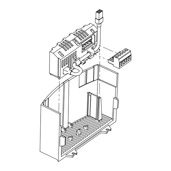
Frequency Inverter. The modules are intended to supplement the standard I/O functions available in the SMVector inverter. The I/O module fi ts into the SMVector inverter terminal cover. This allows for easy fi eld installation and does not add to the overall size of the SMVector inverter. -
Page 8: Installation
Figure 2b: NEMA 4X (IP65) Installation The ESVZAL1 I/O Option Module contains 1 red Terminal Strip of Standard SMVector Inverter wire and 1 black wire that must be wired into the 6 25 4 11 13A 13B 13C 14 30 16 17 standard SMVector Inverter terminal strip. -
Page 9: Module Terminal Block
5mm pluggable connector. Table 2: Additional I/O Terminals Terminal Function Description Relay N.O. Relay Common Relay N.C. Digital Input Available only on ESVZAL1 Digital Input Available only on ESVZAL1 Figure 4: Additional I/O Connector SMVector I/O Module ALSV01 v1.0 13376253... -
Page 10: Electrical Installation
The assertion level of Terminals 13F and 13G will match the assertion level of the Digital Input standard SMVector digital inputs 13A, 13B, 13C, etc. Refer to the description of P120 and Terminal #4 in the SMVector - Frequency Inverter Operating Instructions (SV01) -
Page 11: Commissioning
Refer to the Communications Reference Guide Module Specifi c Parameters p407 … P499 specifi c to the network or I/O module installed. NOTE Set P400 = 8 for the SMVector drive to communicate with the additional I/O module. SMVector I/O Module ALSV01 v1.0 13376253... -
Page 12: Additional I/O Module Parameters
Commissioning Additional I/O Module Parameters In addition to the parameters detailed in the SMVector Frequency Inverter Operating Instructions (SV01), installing the Additional I/O Module provides access to supplementary parameters exclusive to the Additional I/O Module. Table 4 lists these supplementary parameters. - Page 13 (INVERSE AT SPEED) and the relay is energized when the output frequency does not equal the command frequency. NOTE Inverting P140, P142 or P441 when the parameter is set to NONE (0) will result in the output being energized continuously. SMVector I/O Module ALSV01 v1.0 13376253...
-
Page 14: Display
LED # Charge Relay Additional I/O Module only Input 13C Auxiliary Relay Input 13F Input 13A Input 13E Factory Reserved Protective Diagnostic * Input 13D available on 15-60HP (11-45kW) models only Figure 6: Status Indicators SMVector I/O Module ALSV01 v1.0 13376253... - Page 16 SMVector Additional I/O Module ALSV01 v1.0 1337625 Lenze Americas Corporation 630 Douglas Street Uxbridge, MA 01569 800 217-9100 508 278-7873 marketing.us@lenze.com www.Lenze.com Service 508 278-9100 508 278-6620 repair.us@lenze.com...
Need help?
Do you have a question about the SMVector and is the answer not in the manual?
Questions and answers