Table of Contents
Advertisement
Quick Links
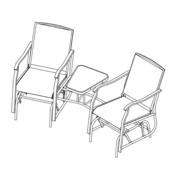
2-Person Glider Set
SKU# 272-0833
MODEL # BJ390
ASSEMBLY AND USER MANUAL
IMPORTANT, RETAIN FOR FUTURE REFERENCE: READ CAREFULLY
The schmatics in this manual are for assembly and operation illustration only.
They may differ from the products's actual appearance.
If you have any questions, concerns or need additional parts please
do not return to the place of purchase. Contact our customer service department toll free at
1-855-880-7205 for further instructions.
For additional product information, please contact our Customer Service Center at 1-855-880-7205 between
8am- 5pm Eastern Time, Monday through Friday.
2014 Distributed by Menard, Inc., Eau Claire, WI 54703
Made in China
Advertisement
Table of Contents

Related Manuals for Backyard Creations BJ390


Summary of Contents for Backyard Creations BJ390
- Page 1 2-Person Glider Set SKU# 272-0833 MODEL # BJ390 ASSEMBLY AND USER MANUAL IMPORTANT, RETAIN FOR FUTURE REFERENCE: READ CAREFULLY The schmatics in this manual are for assembly and operation illustration only. They may differ from the products’s actual appearance. If you have any questions, concerns or need additional parts please do not return to the place of purchase.
-
Page 2: Table Of Contents
CONTENTS Warning and Cautions . . . . . . . . . . . . . . . . . . . . . . . . . . . . . . . 2 Care and Maintenence . -
Page 3: Care And Maintenance
CARE AND MAINTENANCE • Use mild soap and warm water to clean the frames. • Rinse with clean water and dry thoroughly. • Be sure to drain any water accumulated inside the frames. To thoroughly drain frames, remove footcaps and tilt frames, if necessary, to remove all water. Water allowed to accumulate inside the frames and then exposed to sub-freezing temperatures can cause damage to frame tubing. -
Page 4: Hardware Contents
HARDWARE CONTENTS Part Picture Description Quantity Bolt(M6 X 15) Bolt (M6 X 45) Bolt (M6 x 55) Bolt (M6 X 35) Bolt (M6 X 70) Steel Washer Plastic Washer Bolt Cap Nut Cap Inner Hexagon Wrench Outer Hexagon 1 (M6) Wrench... -
Page 5: Package Contents
PACKAGE CONTENTS Please lay out all parts prior to assembly or installation. Read instructions prior to assembly or installation. Part Picture Description Quantity Right Armrest Left Armrest Back Leg Connecting Tube Swing Pole Table Top Support Bracket (small) Table Top Support Bracket (large) Left and Right Seat Connecting Bracket... -
Page 6: Assembly
ASSEMBLY INSTRUCTIONS CAUTION: Do not use sharp equipment such as a knife and scissors when removing the protective material, as it may damage the product.. * Place all glider parts and hardware on a soft & clean level surface. Step 1: Attach swing pole (D) to left leg (J) and right leg (K) with M6*45 Bolt (N), plastic washer (T), steel washer (R) and M6 nut (S), as shown above. -
Page 7: Assembly
ASSEMBLY INSTRUCTIONS Step 3: Attach upper collecting tube (L) to left leg (J) and right leg (K) with M6*55 bolts (O), and M6 nut (S) as shown above. Do not overtighten the bolts. Step 4: Attach left armrest (B) and right armrest (A) to swing pole (D) with M6*45 bolt (N), Plastic washer (T), steel washer (R) and M6 nut (S) as shown above. -
Page 8: Steel Washer
ASSEMBLY INSTRUCTIONS Step 5: Place table top (H) on a clean and soft level surface. Then attach table top support brackets (small) (E) and table top support bracket (large) (F) to table top (H)with M6*15 bolt (M) and steel washer (R) as shown above. Do not overtighten the bolts. Step 6: Attach left and right seat connecting bracket (G) to table top support bracket (small) (E) and table top support bracket (large) (F) with M6*35 bolt (P) and steel washer (R) as shown above, do not overtighten bolts. - Page 9 ASSEMBLY INSTRUCTIONS Step 7: Turn the table over, Insert left and right seat connecting brackets (G) into upper connecting tube of left & right leg (L). Attach it with M6*55 bolt (O), steel washer (R), and M6 nuts (S) as shown above. Do not overtighten the bolts. Step 8: Repeat step 7 to attach other side of the table to glider chair as shown above.
-
Page 10: Bolt Cap
ASSEMBLY INSTRUCTIONS Step 9: Attach back (I) to left (B) & right armrest (A) with M6*70 bolt (Q), pplastic pad (T), steel washer (R), M6 nuts (S) as shown above, do not tighten the bolts too much. Then attach seat (I) to left (B) & right armrest (A) with M6 X35 bolt (P) and steel washer (R) as shown above. -
Page 11: Warranty
WARRANTY 90 DAY WARRANTY This product is covered under a manufacturer’s 90 day warranty from date of purchase against defects in materials and workmanship. This warranty does not cover damage due to neglect, abuse or weather related damage. For full warranty disclosure, email us at customerservice@atleisure.com, call toll free at 1-855-880-7205 or send mail to 1040 Boulevard SE Ste. - Page 12 For additional product information, please contact our Customer Service Center at 1-855-880-7205 between 8am- 5pm Eastern Time, Monday through Friday. 2015 Distributed by Menard, Inc., Eau Claire, WI 54703 MADE IN CHINA...
Need help?
Do you have a question about the BJ390 and is the answer not in the manual?
Questions and answers