Rath SmartRescue 5 Installation & Operation Manual
Hide thumbs
Also See for SmartRescue 5:
- Installation & operation manual (12 pages) ,
- Installation & operation manual (13 pages)

Related Manuals for Rath SmartRescue 5


Summary of Contents for Rath SmartRescue 5
- Page 1 Installation & Operations Manual SmartRescue 5 & 10 N56W24720 N. Corporate Circle Sussex, WI 53089 RP8500510 800-451-1460 262-246-4828 (fax) Made in the USA Ver. 1 www.rathmicrotech.com www.area-of-refuge.com 3 Year Warranty 12/17...
-
Page 2: Table Of Contents
Thank you for purchasing Rath’s SmartRescue. We are the largest Emergency Phone Manufacturer in North America and have been in business for over 35 years. We take great pride in our products, service, and support. Our Emergency Phones are of the highest quality. -
Page 3: Pre-Installation Requirements
• 120V power • Determine Communication: • Dedicated analog phone line from POTS, PBX, or Central Office • VoIP - requires use of Rath Model 2100-VoIP to connect SmartRescue to VoIP phone system • Internal Intercom (no offsite calling) - requires Rath Model 2100-Linesim • Digital or Cellular connect - Call Rath 800-451-1460 • Twisted, shielded 22 or 24 AWG wire cabling to connect each Emergency Phone to the SmartRescue Base Station •... -
Page 4: Wiring Smartrescue To 120V Power Source
Phone Push Connector 6 Phone Push Connector 7 Phone Push Connector 8 Phone Push Connector 9 Phone Push Connector 10 Handset Connection Supplied by Dedicated Analog Rath! Phone Line Optional Sub-Master Phone Ports Battery Backup 120vac NEUTRAL 24V Power Input... -
Page 5: Wiring Emergency Phones To Smartrescue
To SmartRescue: Insert 4 wires for each phone as shown on the SmartRescue Diagram To Phone: Wire out to a standard 2-pair RJ11 phone jack. Connect this jack to the 5’ cord supplied by Rath. SmartRescue The Emergency Phones come with a 5’ cord with an RJ11 on both ends. -
Page 6: Programming Options For Smartrescue
Programming Options for SmartRescue Programming the SmartRescue Step 7 Mount the front cover back onto the enclosure. Step 8 Programming Options for SmartRecue Option 1 Factory Default: The Emergency Phones will call directly offsite and not stop at the SmartRescue. That phone’s button will light at the SmartRescue during the call. (Keep in Default Mode if site is not manned 24/7 to answer calls onsite) Option 2 Program the SmartRescue to Allow the Emergency Phones to call the SmartRescue first, then outside number(s):... -
Page 7: Powering Emergency Phones
2 Pair- Twisted 24-22ga Do NOT power SmartRescue with this 2500-PWR24 Ground To 120vac Neutral Option 2 Transformers: Only applicable if your phone comes with one supplied by Rath Page 3 Option 3 Page 7 Powered Directly by Elevator Car... -
Page 8: Programming Options For Phones
Programming the Phone(s) Programming the Phone(s) Step 10 1. Options for programming the phone(s) Option 1 Call emergency numbers offsite, without stopping at the SmartRescue a. Press Enter to get into program mode b. Press 1, Enter, (Emergency Number), Stop c. If using two emergency numbers: Press 2, Enter, (Emergency Number), Stop d. -
Page 9: Operations/Testing System
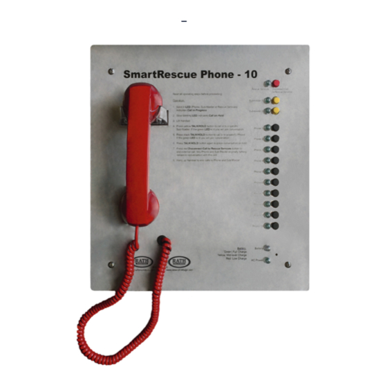
Operations & Testing Operation/ Testing System 1. Once all connections are made, the following LEDs should be lit: • Power LED, located on bottom edge of the face plate, will be constantly lit green. • Battery LED, located on bottom edge of the face plate, will be constantly lit: • Red = Low level charge • Yellow = Mid level charge • Green = Full charge 2. Initiate a call to an Emergency Phone or Sub-Master from the SmartRescue Base Station: a. Lift handset on SmartRescue Base Station b. -
Page 10: System Supervision - Area Of Refuge
Appendix System Supervision Area of Refuge Systems, NFPA required (Not required for Elevator Industry) NFPA-2016 24.10.4 - All pathways between a remote area of refuge station and the central control point shall be monitored for integrity. 24.13.4 Power Supplies: All control units shall meet the power supply requirements of section 10.6s 10.6.9 Monitoring Integrity of Power Supplies 10.6.9.1 Unless otherwise permitted or required by 10.6.9.1.3 and 10.6.9.1.6 all primary and secondary power supplies shall be monitores for the presence of voltage at the point of connection to the system. -
Page 11: Phone Line Supervision - Elevator Industry
Phone Line Supervision Elevator Industry REQUIRES notification if phone line is lost Rath SmartPhones have a built-in Line Check Feature. The phone constantly looks for a phone line. When a phone line is not detected it will trigger the onboard relay. Connect the relay to one of Rath’s alarm devices, 2100-Alarm or OEM versions. Elevator Code Phone Line Detection Code Compliant (2.27.1.1.6) •... -
Page 12: Submaster Installation
Appendix 2300-630SM Submaster Installation & Operation Installation: • Mount the Submaster to the wall in a desired location • Run twisted 22 or 24 AWG 4-wire cabling to connect the Submaster to the SmartRescue • Emergency Phones MUST be in Consolidator Mode (see page 12) Operation: • Lift handset •... -
Page 13: Smartrescue System Activation Relay
Appendix SmartRescue System Activation Relay TB1 Relay When an Emergency phone has been activated, this relay changes state and can be connected to an alarm panel, strobe, or other notification means. Programming SmartRescue back to default settings a. Hold down Red Disconnect and Submaster 1 buttons for 5 seconds b. Release buttons (you will hear a confirmation tone) c. -
Page 14: Adjusting Volume On Smartphones
Appendix Adjusting Volume on SmartPhone (VR1) a. Locate the silver VR1 port on the bottom right corner of the SmartPhone board b. Using a fine Philips Head screwdriver, turn the VR1 clockwise to increase the volume and counterclockwise to decrease the volume Troubleshooting Problem Possible Cause & Solutions Power LED is not • Check to make sure the transformer is connected to a good 120V power source. illuminated: If 24V powered, check the power supply.
Need help?
Do you have a question about the SmartRescue 5 and is the answer not in the manual?
Questions and answers