Advertisement
Quick Links
Advertisement

Related Manuals for Serpent 966


Summary of Contents for Serpent 966
- Page 1 INSTRUCTION MANUAL & REFERENCE GUIDE...
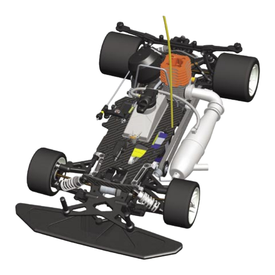
- Page 2 Serpent’s hugely-successful 960 lineage, The exploded views and parts lists for the combining ultimate performance into a single Serpent 966 are included in the back of this package. The Serpent 966 was designed to manual. The exploded views show all the...
- Page 3 (CA) or One-way Lube (OW). (Items not included.) SERPENT.COM The printed instruction manual included with From the Serpent 966 product page you will your Serpent 966 kit is very complete, though find the very latest information about your due to continuous product development,...
- Page 4 Change the position of BOTH eccentric hubs to adjust front belt Page tension. Both hubs should have the same position.
- Page 5 Insert setting - hole mounted to outside M4x12 M4x12 M4x12 M4x12 M4x8 M4x8 M4x8 M4x8 M4x4 M4x4 Page Page Completed assembly...
- Page 6 Servo Saver Ackermann insert position M3x6 M3x6 0.5mm M4x10 Press anti-roll bars into mounts far enough so the bars do not bind when the suspension is compressed M4x6 M4x6 M3x12 M3x16 M3x8 Page...
- Page 7 Spacer Placement M5x6 M5x6 M3x4 Note Orientation of eccenter M3x6 M3x3 2.4mm BOTTOM 1.5mm Page Page...
- Page 8 Assemble L & R steering rods: 87.5mm M3x6 M3x6 M4x8 M4x8 Page...
-
Page 9: Rear Assembly
REAR ASSEMBLY Insert setting - hole mounted to top M3x10 M3x10 M3x6 M4x10 M3x6 M3x10 M3x10 M3x8 M3x8 M3x8 M3x8 M3x8 M3x8 Page Page... - Page 10 41.8mm Page...
- Page 11 M3x4 Assemble both rear hubs using the indicated steps. 5.0mm Front 5.7mm M3x10 M3x10 M3x6 M3x10 Page Page M3x10...
- Page 12 M3x16 M3x16 Default Rear Body Mount Mounting Position Page...
- Page 13 Page Page...
- Page 14 M4x4 M4x4 Assemble L & R linkages 50mm M3x3 M3x3 Page...
- Page 15 Use the following servo arms with these brands of servos. 23 - Sanwa / KO / JR 24 - Hitec 25 - Futaba M3x6 Steering Linkage STEERING SERVO 45.5mm Servo output shaft must be towards FRONT of the car. M3x16 Note the orientation of the M3x16 servo mounting screw blocks.
- Page 16 OPTION 1: Laydown Throttle Servo M3x10 M3x10 M3x6 Use the following servo arms with these brands of servos. 23 - Sanwa / KO / JR M3x6 Throttle Linkage 24 - Hitec 25 - Futaba 36mm OPTION 1: Laydown Throttle Servo M3x10 M3x10 Securely attach receiver...
- Page 17 OPTION 2: Upright Throttle Servo M3x16 M3x16 Securely attach receiver to mounting plate. RACING TIP: To protect the receiver against fuel and moisture, seal the wired receiver into a rubber balloon before mounting it. M3x12 M3x12 FUEL CAP FITTING PLACEMENT CW tracks: Fitting on RIGHT side.
- Page 18 M4x10 M4x10 M4x10 M4x10 M4x10 M4x10 M4x10 M4x10 Servo Saver Steering Page Linkage...
- Page 19 M4x4 M4x4 Unscrew the bottom half of the pre-assembled shock absorbers. FILLING Fill the shock body with the supplied shock absorber oil. BLEEDING Let the oil settle and allow the air to escape. Slowly move the piston up and down to release any trapped air bubbles.
- Page 20 With the shock body filled with oil, slowly screw the bottom half of the pre-assembled shock back onto the shock body. IMPORTANT! Do not cross thread! Front shock Oil will overflow through the 68mm built-in bleed channel in the threads. Rear shock 73mm M3x6...
- Page 21 Note the middle shock mount Purple Spring holes used. M3.5x13 M3.5x13 M4x10 M4x10 M4x10 M4x16 Page Page M4x16...
-
Page 22: Gearbox Assembly
GEARBOX ASSEMBLY M3x12 SHIFT POINT GAP SETTING screw screw M3x3 Start with screw head flush with bottom edge of hole. Both screws must be set equally. M3x3 M3x12 SHIFT POINT screw M3x6 M3x6 M3x6 1st Gear 48 T Page... - Page 23 2nd Gear 45 T M3x6 M3x6 M3x6 M3x8 ADJUSTING THE 2-SPEED SHOE GAP Loosed the two gap-setting set screws to allow the shoes to rest on the drive adaptor. Install the 2-speed shoes in the 2nd gear drum, but do NOT install the 1st gear. There should be equal but minimal spacing between the 2-speed shoes and the 2nd gear drum.
- Page 24 CENTAX ASSEMBLY IMPORTANT! Use the cone that comes with your engine Page...
- Page 25 1.2mm Initial clutch spring tension Note inside shoulders 2nd Gear 19 T 1st Gear 16 T 5.2mm 5.0mm IMPORTANT! Install thrust bearing plates as shown Large inner dia. Small inner dia. M3x16 Page Page...
- Page 26 ADJUSTING THE CLUTCH GAP Install only the clutchbell and the thrustbearing assembly on the engine crankshaft. Push the clutchbell onto the clutch shoe, and then measure the distance A as indicated. Push Pull the clutchbell away from the clutch shoe, and then measure the distance B as indicated.
-
Page 27: Final Assembly
FINAL ASSEMBLY M3X16 M3X16 M5X12 M5X12 M4x16 M4x10 M3x16 Page Page Orientation of belt tensioner bearings... - Page 28 M3x3 M3x3 OPTION 1: Laydown Throttle Servo M3x16 Throttle Lever M3x3 M3x3 OPTION 2: Upright Throttle Servo Use the following servo arms with these brands of servos. 23 - Sanwa / KO / JR 24 - Hitec 25 - Futaba OPTION 1: Laydown Throttle Servo Completed throttle/brake linkage M3x6...
- Page 29 OPTION 2: Upright Throttle Servo Completed throttle/brake linkage M3x6 M3x6 Side belt tension adjustment Looser Tighter M4x12 M4x6 Page Page...
- Page 30 M3x6 M3x6 M3x6 M3x6 Securely attach battery pack to mounting plate. Page...
- Page 31 Page Page...
- Page 32 REFERENCE GUIDE...
- Page 35 1493 1602 1602 902116 902116 902116 903278 902115 903136 903136 902119 902170 110109 1070 110109 903102 110112 110104 110112 OPTION: Laydown Throttle Servo 110110 110110 903135 903134 110109 110108 110110 110108 901158 - 23 902138 901159 - 24 1650 901160 - 25 1660 110108 902121...
- Page 38 #902410 - 2 Speed gearbox LC (no shaft incl.) #903116 - 2 Speed shaft 960 110112 110122 6626 110116 1342 902411 902445 - 45T 902444 - 44T* 902446 - 46T* 902416 902412 902420 1320 902448 - 48T 902447 - 47T* 902449 - 49T* 902413 110122...
- Page 40 SERPENT 966 PARTS LIST ART. DESCRIPTION 903332 Shock RCC 2009 revision set 903009 Serpent 966 1/8 4WD KIT 903333 X-ring RCC 2009 Shock 903334 Shock-set short ‘09 (2) 903335 Shock-set long ‘09 (2) MANUAL & DECALS 903327 Manual & Reference guide 966...
- Page 41 1599 Exhaust mounting wire 903312 Suspension Bracket rear rr 903201 Engine monoblock M21 903313 Shocktower 966 rear 903314 Upper supension bracket FR 966 903315 Upper supension bracket rr 966 OPTION PARTS 903316 Bearing block-2sp-R 966 1015 Engine mount screws Torx / washers (4)
- Page 42 1646 Steel balls 6mm M3 (4) 1647 Steel balls 6mm (4) 1650 Balls 6mm/setscrews hex (4) BODIES AND WINGS 903325 Screw set 966 (178) 1601 Body clips (10) 1729 Screw-nut M6 black nylon (2) TOOLS 1461 Tool front anti-roll bar...
- Page 44 Serpent Model Racing Cars BV Spaarneweg 12E, 2142 EN, Cruquius The Netherlands, Europe...
Need help?
Do you have a question about the 966 and is the answer not in the manual?
Questions and answers