Table of Contents
Advertisement
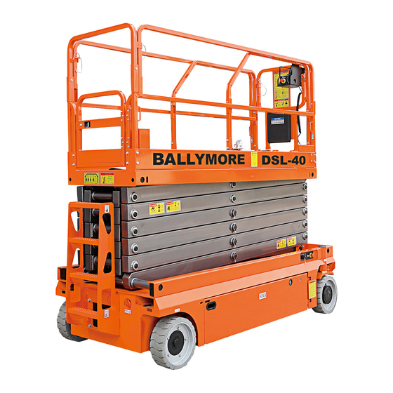
SELF-PROPELLED SCISSOR LIFTS
OPERATOR'S MANUAL
Part Number: SM0114113
Ballymore Company, Inc.
Zhejiang Dingli Machinery Co., Ltd.
with Maintenance Information
DSL-40
THE MANUFACTURER SHALL NOT BE HELD LIABLE IN CASE OF FAULTS
OR ACCIDENTS DUE TO NEGLIGENCE, INCAPACITY, INSTALLATION BY
UNQUALIFIED TECHNICIANS AND IMPROPER USE OF THE MACHINE
DO NOT OPERATE THIS MACHINE UNTIL YOU READ AND UNDERSTAND
ALL THE DANGERS,WARNINGS AND CAUTIONS IN THIS MANUAL
WARNING
Second Edition, January 2016 Printing
ANSI
Advertisement
Table of Contents

Summary of Contents for Ballymore SM0114113
- Page 1 UNQUALIFIED TECHNICIANS AND IMPROPER USE OF THE MACHINE DO NOT OPERATE THIS MACHINE UNTIL YOU READ AND UNDERSTAND ALL THE DANGERS,WARNINGS AND CAUTIONS IN THIS MANUAL ANSI Part Number: SM0114113 Ballymore Company, Inc. Second Edition, January 2016 Printing Zhejiang Dingli Machinery Co., Ltd.
- Page 2 OPERATOR’S MANUAL with Maintenance Information Version of the Record Version of the Record Version Number Create Date SM0114113_Rev1.0 …………………………………………………………………………… 2014-12 SM0114113_Rev2.0 …………………………………………………………………………… 2015-10...
-
Page 4: Table Of Contents
Comply with employer, job site and part of your machine and should remain with governmental rules. the machine at all times. If you have any questions, please call BALLYMORE INC. Read, understand and follow the instructions in this and other manuals supplied with this machine. -
Page 6: Safety Rules
OPERATOR’S MANUAL with Maintenance Information Safety Rules Danger Decal Legend Failure to obey the instructions and BALLYMORE/DINGLI product decals use symbols, color coding and signal words to safety rules in this manual will identify the following: result in death or serious injury. - Page 7 OPERATOR’S MANUAL with Maintenance Information Safety Rules Allow for platform movement, electrical line Intended Use sway or sag and beware of strong or gusty This machine is intended to be used only to lift winds. personnel, along with their tools and materials Keep away from the machine if it contacts to an aerial work site.
- Page 8 OPERATOR’S MANUAL with Maintenance Information Safety Rules across uneven terrain, debris, unstable or Work Area Safety slippery surfaces and near holes and Do not raise the platform unless the machine drop-offs. is on a firm, level surface. Do not drive the machine on or near uneven Do not drive over 0.5 mph / 0.8 km/h with the terrain, unstable surfaces or other hazardous platform raised.
- Page 9 OPERATOR’S MANUAL with Maintenance Information Safety Rules Do not push the machine or other objects with Do not use the machine on a moving or mobile the platform. surface or vehicle. Do not operate the machine with the chassis Be sure all tires are in good condition, air-filled trays open.
- Page 10 OPERATOR’S MANUAL with Maintenance Information Safety Rules rails are properly installed and the entry is secured for operation. Do not enter or exit the platform unless the machine is in the stowed position. Collision Hazard Be aware of limited sight distance and blind spots when driving or operating.
- Page 11 OPERATOR’S MANUAL with Maintenance Information Safety Rules Bodily Injury Hazard Do not operate the machine with a hydraulic oil or air leak. An air leak or hydraulic leak can penetrate and/or burn skin. Improper contact with components under any Limit travel speed according to the condition of cover will cause serious injury.
- Page 12 OPERATOR’S MANUAL with Maintenance Information Safety Rules entire charging cycle. Do not contact the battery terminals or the cable clamps with tools that may cause sparks. Component Damage Hazard Do not use any battery charger greater than 24V to charge the batteries. Electrocution/ Burn Hazard Connect the battery charger to a grounded, AC 3-wire...
-
Page 13: Legend
OPERATOR’S MANUAL with Maintenance Information Legend Legend 1 Platform extension 10 Lift Cylinder 2 Manual storage container 11 Ground controls (on opposite side of 3 Platform control machine) 4 Lanyard anchorage point 12 Entry ladder 5 Platform guard rails 13 Brake release pump 6 Platform extension release pedal 14 Non-steer tire 7 Main Platform... - Page 14 OPERATOR’S MANUAL with Maintenance Information Decals Decal Inspection Use the pictures on the next page to verify that all decals are legible and in place. Below is a numerical list with quantities and descriptions. Part No. Description Qty. Remark Notice – Operator’s manual storage 9334011 Danger –...
- Page 15 OPERATOR’S MANUAL with Maintenance Information Decals Danger – Safety arm 9413011 Instructions – Forklift pockets 9311011 Instructions – Tie down point 9311015 Instructions – Lift point 9311013 Instructions – Wheel load: 2948 lbs 9311421 Part No. Description Qty. Remark Notice – Main power switch operation 9311105 Warning –...
-
Page 16: Decals
OPERATOR’S MANUAL with Maintenance Information Decals 7 7 7... - Page 17 OPERATOR’S MANUAL with Maintenance Information Decals...
-
Page 18: Specifications
Controls Proportional configurations. It should be used only with adequate safety factors. AC outlet in platform Standard Continuous improvement of our products is a Ballymore policy. Product specifications are subject to change without notice or obligation. -
Page 19: Control Panel
OPERATOR’S MANUAL with Maintenance Information Control Panel Ground Control Panel ○ ○ ○ ○ ○ 1 Key switch for platform / off / ground control 3 7 amp breaker for electric circuits selection Turn the key switch to the platform position 4 Indicator light and the platform controls will operate. - Page 20 OPERATOR’S MANUAL with Maintenance Information Control Panel Platform Control Panel ○ ○ ○ ○ ○ ○ ○ ○ ○ Horn button Thumb rocker switch for steer functions Lift function select button Drive function select button Proportional control handle Drive speed button Function enable switch for lift and drive Red Emergency Stop button functions...
- Page 21 OPERATOR’S MANUAL with Maintenance Information Control Panel Platform Control Panel Thumb rocker switch for steer functions Lift function select button Press the thumb rocker switch in either Press this button to activate the lift direction to activate steer function. function. Drive function select button Proportional control handle Press this button to activate the drive...
-
Page 22: Pre-Operation Inspection
OPERATOR’S MANUAL with Maintenance Information Pre-operation Inspection Do Not Operate Unless: Fundamentals √ You learn and practice the principles of It is the responsibility of the operator to perform a pre-operation inspection and routine safe machine operation contained in this maintenance. - Page 23 OPERATOR’S MANUAL with Maintenance Information Pre-operation Inspection Pre-operation Inspection Check entire machine for: Be sure that the operator’s manual are Cracks in welds or structural complete, legible and in the storage container located in the platform. components ...
-
Page 24: Workplace Inspection
OPERATOR’S MANUAL with Maintenance Information Workplace Inspection Fundamentals Do Not Operate Unless: The workplace inspection helps the operator √ You learn and practice the principles of determine if the workplace is suitable for safe safe machine operation contained in this machine operation. -
Page 25: Function Tests
OPERATOR’S MANUAL with Maintenance Information Function Tests Fundamentals Do Not Operate Unless: The function tests are designed to discover √ You learn and practice the principles of any malfunctions before the machine is put safe machine operation contained in this into service. - Page 26 OPERATOR’S MANUAL with Maintenance Information Function Tests Select a test area that is firm, level and switch. free of obstruction. ⊙ Result: The platform should rise. Be sure the battery pack is connected. 12 Move down and hold the platform up / At the Ground Controls down switch.
- Page 27 OPERATOR’S MANUAL with Maintenance Information Function Tests in the direction indicated by the yellow Test Drive and Braking arrow. 30 Press and hold the function enable switch ⊙ Result: No functions should operate. on the control handle. 21 Press the lift function select button. 31 Slowly move the control handle in the direction indicated by the blue up arrow on 22 Press and hold the function enable switch...
- Page 28 OPERATOR’S MANUAL with Maintenance Information Function Tests ⊙ Result: Before the platform is raised 6.6 ft / raised exceeds 0.72 ft per second / 22 cm/s, immediately tag and remove the 2 m from the ground, an alarm should machine from service. sound and the drive function should not Work.
-
Page 29: Operating Instructions
OPERATOR’S MANUAL with Maintenance Information Operating Instructions Fundamentals Do Not Operate Unless: √ You learn and practice the principles of This machine is a self-propelled hydraulic lift equipped with a work platform on the scissor safe machine operation contained in this mechanism. -
Page 30: Maintenance
OPERATOR’S MANUAL with Maintenance Information Operating Instructions Move the control handle according to the Emergency Stop markings on the control panel. Push in the red Emergency Stop button to the To Steer off position at the ground controls or the platform controls to stop all machine functions. - Page 31 OPERATOR’S MANUAL with Maintenance Information Operating Instructions Driving on a slope Operation from Ground with Determine the slope and side slope ratings for the machine and determine the slope grade. Controller Maximum slope rating, stowed position level Maintain safe distances between operator, 25% (14°), Maximum side slope rating, stowed machine and fixed objects.
- Page 32 OPERATOR’S MANUAL with Maintenance Information Operating Instructions Fully lower the platform and retract the To Extend and Retract Platform platform extension. Press the platform lock pin pedal on the Remove the platform controls. extension deck by foot. From inside the platform, remove the two Push the platform extension guardrail to front extension deck wire lock pins.
- Page 33 OPERATOR’S MANUAL with Maintenance Information Operating Instructions Error indicator readout If the LED diagnostic readout displays an error code, such as LL, push in and turn the red Emergency Stop button to reset the system. List of Fault Codes Display Description Lift Reaction System initialization Fault...
- Page 34 OPERATOR’S MANUAL with Maintenance Information Operating Instructions Display Description Lift Reaction Motor Controller Motor Output Fault Controller Dependent Motor Controller SRO Fault Controller Dependent Motor Controller Throttle Fault Controller Dependent Motor Controller Emergency Reverse Fault Controller Dependent Motor Controller HPD Fault Controller Dependent Low Voltage Fault Disable All Motion...
- Page 35 Platform Joystick not in neutral at power-up Message: Make sure that the Joystick is in the neutral (upright) position. Check the neutral zone parameter setting in Ballymore/ Dingli Scissor Programmer. If it’s OK, consider replacing the Joystick or the PCU.
- Page 36 Motor Controller Motor Output fault: Check wiring first then cycle power. If needed replace controller. Motor Controller SRO Fault: Look at motor enable delay with the Ballymore/ Dingli Scissor Programmer, it may be too short. Make sure other Motor Controller parameters are properly selected.
- Page 37 Over 90% Load Warning: Platform is getting close to its limit of weight. Consider not adding more load. Over 99% Load Warning: Platform has reached its limit of weight. Do not add more load. For more information, please consult the appropriate Ballymore Service Dept.
- Page 38 Do not overfill. √ Use proper AC input voltage for charging as indicated on the charger. Dry Battery Filling and √ Use only a Ballymore authorized battery Charging Instructions and charger. Remove the battery vent caps and permanently remove the plastic seal from To Charge Battery the battery vent openings.
- Page 39 OPERATOR’S MANUAL with Maintenance Information Transport and Lifting Instructions Observe and Obey: Brake Release Operation √ Common sense and planning must be For the DC Motor Drive Model applied to control the movement of the Chock the wheels to prevent the machine machine when lifting it with a crane or from rolling.
- Page 40 OPERATOR’S MANUAL with Maintenance Information Transport and Lifting Instructions Towing the Hydraulic Drive Model is not Turn the key switch to the off position and recommended. If the machine must be towed, remove the key before transporting. do not exceed 2.2 mph / 3.5 km/h. Inspect the entire machine for loose or Towing the DC Motor Drive Model is not unsecured items.
- Page 41 OPERATOR’S MANUAL with Maintenance Information Transport and Lifting Instructions √ Only qualified riggers should rig and lift the Lifting the Machine with a machine. Forklift √ Only qualified forklift operators should lift Be sure the extension deck, controls and the machine with a forklift. component trays are secure.
- Page 42 OPERATOR’S MANUAL with Maintenance Information Transport and Lifting Instructions Lifting Instructions Center of Gravity Fully lower the platform. Be sure the extension Model X Axis Y Axis decks, controls and covers are secure. Remove all loose items on the machine. DSL-40 83 cm 72.1cm...
- Page 43 OPERATOR’S MANUAL with Maintenance Information Maintenance Pre-delivery Preparation Report Observe and Obey: The pre-delivery preparation report contains √ Only routine maintenance items specified in checklists for each type of scheduled this manual shall be performed by the inspection. operator. Make copies of the Pre-delivery Preparation √...
- Page 44 OPERATOR’S MANUAL with Maintenance Information Maintenance Pre-delivery Preparation Report Fundamentals Instructions Use the operator’s manual on your machine. It is the responsibility of the dealer to perform the Pre-delivery Preparation. The Pre-delivery Preparation consists of The Pre-delivery Preparation is performed completing the Pre-operation Inspection, the prior to each delivery.
- Page 45 OPERATOR’S MANUAL with Maintenance Information Maintenance Maintenance Inspection Report Checklist A Y N R Model A-1 Inspect the manuals and decals Serial number A-2 Pre-operation inspection Date A-3 Check the Batteries Hour meter A-4 Check the Hydraulic Oil Level Machine owner A-5 Function tests Inspected by (print) Perform after 40 hours:...
- Page 46 Note: Contact your authorized BALLYMORE possible hazards associated with using this distributor or BALLYMORE Inc. if replacement machine. They also provide users with manuals or decals are needed. operation and maintenance information. An...
- Page 47 OPERATOR’S MANUAL with Maintenance Information Maintenance Perform Pre-operation Inspection Check the Batteries Completing a Pre-operation Inspection is essential to safe machine operation. The Pre-operation Inspection is a visual inspection Proper battery condition is essential to good performed by the operator prior to each work machine performance and operational safety.
- Page 48 OPERATOR’S MANUAL with Maintenance Information Maintenance Check the Hydraulic Oil Level Perform Function Tests Completing the function tests is essential to safe machine operation. Function tests are designed to discover any malfunctions before Maintaining the hydraulic oil at the proper level the machine is put into service.
- Page 49 OPERATOR’S MANUAL with Maintenance Information Maintenance Perform 30 Day Service Grease the Steer Yokes BALLYMORE/ DINGLI requires that this The 30 day maintenance procedure is a one procedure be performed every 100 hours of time procedure to be performed after the first operation.
- Page 50 OPERATOR’S MANUAL with Maintenance Information Maintenance Checklist B Procedures Inspect the Batteries Models without maintenance-free or sealed BALLYMORE/ DINGLI requires that this batteries: procedure be performed every 250 hours or quarterly, whichever comes first. Remove the battery vent caps and check...
- Page 51 Note: For best results, use an extension of adequate size with a length no longer than 50 ft / 15 m. Note: If you have any further questions regarding the battery charger operation, please contact the BALLYMORE Service Department. a batteries b 300A fuse c battery charger...
- Page 52 Inspect the Electrical Wiring the platform. Inspect the center chassis area and scissor arms for burnt, chafed and pinched BALLYMORE/ DINGLI requires that this cables. procedure be performed every 250 hours or quarterly, whichever comes first. Inspect the following areas for burnt,...
- Page 53 Maintenance Inspect the Tires and Wheels Test the Emergency Stop (including castle nut torque) BALLYMORE/ DINGLI requires that this procedure be performed every 250 hours or quarterly, whichever comes first. BALLYMORE/ DINGLI requires that this A properly functioning Emergency Stop is procedure be performed every 250 hours or essential for safe machine operation.
- Page 54 OPERATOR’S MANUAL with Maintenance Information Maintenance Test the Key Switch Test the Automotive-style Horn (if equipped) BALLYMORE/ DINGLI requires that this procedure be performed every 250 hours or BALLYMORE/DINGLI requires that this quarterly, whichever comes first. procedure be performed every 250 hours or quarterly, whichever comes first.
- Page 55 OPERATOR’S MANUAL with Maintenance Information Maintenance Test the Drive Brakes Choose a point on the machine; i.e., BALLYMORE/ DINGLI requires that this contact patch of a tire, as a visual procedure be performed every 250 hours or reference for use when crossing the test quarterly, whichever comes first.
- Page 56 Test the Drive Speed - Stowed Test the Drive Speed - Raised Position Position BALLYMORE/ DINGLI requires that this BALLYMORE/ DINGLI requires that this procedure be performed every 250 hours or procedure be performed every 250 hours or quarterly, whichever comes first.
- Page 57 Raise the platform approximately 6.6 ft / 2 m from the ground. Press the drive function select button. BALLYMORE/ DINGLI requires that this procedure be performed every 250 hours or Choose a point on the machine; i.e., quarterly, whichever comes first.
- Page 58 Bring the machine to top drive speed BALLYMORE/ DINGLI requires that this before reaching the start line. Begin timing procedure be performed every 250 hours or when your reference point on the machine quarterly, whichever comes first.
- Page 59 Inspect the Hydraulic Tank Cap Check the Module Tray Latch Venting System Components BALLYMORE/ DINGLI requires that this BALLYMORE/ DINGLI requires that this procedure be performed every 250 hours or procedure be performed quarterly or every 250 quarterly, whichever comes first.
- Page 60 B-14 Test the Down Limit Switch and the Pothole Limit Switches Securely install the platform control box BALLYMORE/ DINGLI requires that this harness plug into the 6-pin Deutsch procedure be performed every 250 hours or connector of the ECU cable.
- Page 61 OPERATOR’S MANUAL with Maintenance Information Maintenance machine is functioning properly. Pothole Limit Switches ¤ Result: The diagnostic display does not 28 Move the machine onto a grade which show code 18 and the alarm does not exceeds the rating of the level sensor. sound.
- Page 62 Adjust or replace the pothole limit switch. BALLYMORE/ DINGLI requires that this 34 Press the drive function select button. procedure be performed every 250 hours or Attempt to steer or drive the machine.
- Page 63 OPERATOR’S MANUAL with Maintenance Information Maintenance Checklist C Procedures Test the Platform Overload System (if equipped) BALLYMORE/ DINGLI requires that this procedure be performed every 500 hours or six months, whichever comes first OR when the machine fails to lift the maximum rated load.
- Page 64 OPERATOR’S MANUAL with Maintenance Information Maintenance 16 Lift the safety arm, move it to the center of the scissor arm and rotate the safety arm away from the machine and let it hang down. 17 Lower the platform onto the safety arm. a up limited switch Crushing hazard.
- Page 65 OPERATOR’S MANUAL with Maintenance Information Maintenance Replace the Hydraulic Tank Breather BALLYMORE/ DINGLI requires that this procedure be performed every 500 hours or semi-annually, whichever comes first. The hydraulic tank is a vented-type tank. The breather cap has an internal air filter that can become clogged or, over time, can deteriorate.
- Page 66 Checklist D Procedures Check the Scissor Arm Wear Pads Measure the distance between the number BALLYMORE/ DINGLI requires that this one inner arm cross tube and the chassis procedure be performed every 1000 hours or deck at the battery pack side of the annually, whichever comes first.
- Page 67 OPERATOR’S MANUAL with Maintenance Information Maintenance Replace the Hydraulic Tank Return Filter Element BALLYMORE/ DINGLI requires that this procedure be performed every 1000 hours or annually, whichever comes first. Replacement of the hydraulic tank return filter is essential for good machine performance and service life.
- Page 68 Maintenance Checklist E Procedure Test or Replace the Hydraulic Oil Remove the hydraulic tank retaining BALLYMORE/ DINGLI requires that this fasteners and remove the hydraulic tank procedure be performed every 2000 hours or from the machine. every two years, whichever comes first.
- Page 69 OPERATOR’S MANUAL with Maintenance Information Maintenance 12 Install the hydraulic pump inlet line into the tank. Install the fitting onto the pump and torque. 13 Install the hydraulic pump return line into the tank. Install the fitting onto the hydraulic filter head and torque. 14 Fill the tank with hydraulic oil until the fluid is full in the hydraulic tank.
- Page 70 OPERATOR’S MANUAL with Maintenance Information Schematic DSL-40 Platform Overload Sensor Upper Lift Cylinder Lower Lift Cylinder Steer Cylinder ORF2 ORF1 FRRV1...
- Page 71 OPERATOR’S MANUAL with Maintenance Information Schematic DSL-40...
- Page 72 OPERATOR’S MANUAL with Maintenance Information Inspection and Repair Log Inspection and Repair Log Date Comments...
Need help?
Do you have a question about the SM0114113 and is the answer not in the manual?
Questions and answers