Advertisement
Table of Contents
- 1 Table of Contents
- 2 Package Contents
- 3 Hardware Contents
- 4 Safety Information
- 5 Preparation
- 6 Initial Installation
- 7 Standard or Angle Mounting Instructions
- 8 Wiring
- 9 Final Installation
- 10 Operating Instructions
- 11 Care and Maintenance
- 12 Troubleshooting
- 13 Limited Lifetime Warranty
- 14 Replacement Parts List
- Download this manual
Harbor Breeze® is a registered trademark
of LF, LLC. All Rights Reserved.
ATTACH YOUR RECEIPT HERE
Purchase Date _________________________
Questions, problems, missing parts? Before returning to your retailer, call our customer
service department at 1-800-643-0067, 8 a.m. - 6 p.m., EST, Monday - Thursday, 8 a.m. - 5 p.m.,
EST, Friday.
AB17988
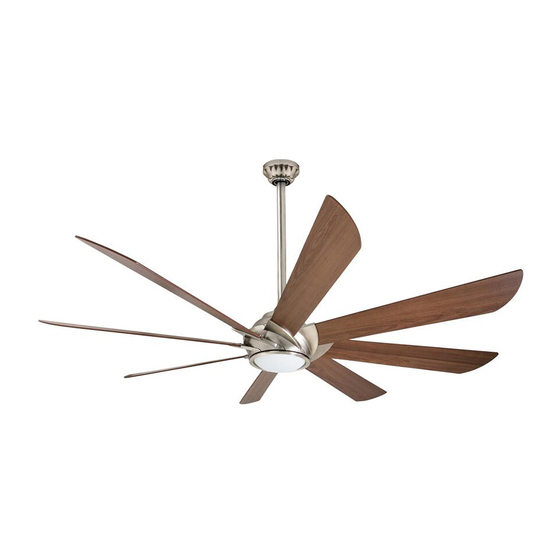
HYDRA CEILING FAN
1
ITEM #0883783
MODEL #41371
Español p. 20
Advertisement
Table of Contents

Related Manuals for Harbor Breeze 0883783


Summary of Contents for Harbor Breeze 0883783
- Page 1 ITEM #0883783 HYDRA CEILING FAN MODEL #41371 Harbor Breeze® is a registered trademark Español p. 20 of LF, LLC. All Rights Reserved. ATTACH YOUR RECEIPT HERE Purchase Date _________________________ Questions, problems, missing parts? Before returning to your retailer, call our customer service department at 1-800-643-0067, 8 a.m.
-
Page 2: Table Of Contents
TABLE OF CONTENTS Package Contents ..............3 Hardware Contents . -
Page 3: Package Contents
PACKAGE CONTENTS 2hr 4hr 8hr PART DESCRIPTION QUANTITY Downrod Downrod Pin (preassembled to Downrod [A]) Downrod Clip (preassembled to Downrod [A]) Mounting Bracket (preassembled to Canopy [E]) Canopy Canopy Cover (preassembled to Canopy [E]) Motor Assembly Fitter Plate (preassembled to Motor Assembly [G]) Fitter Plate Screw (preassembled to the Fitter Plate [H]) Blade Arm (preassembled to Motor Assembly [G]) Light Kit... -
Page 4: Hardware Contents
HARDWARE CONTENTS (shown actual size) Wire Connector Blade Screw Blade Washer Qty. 3 Qty. 24 Qty. 24 + 1 extra + 1 extra + 1 extra... -
Page 5: Safety Information
SAFETY INFORMATION Please read and understand this entire manual before attempting to assemble, operate or install the product. • Before you begin installing the fan, disconnect the power by removing fuses or turning off the circuit breakers. • Make sure all electrical connections comply with local codes, ordinances, the National Electrical Code and ANSI/NFPA 70-199. Hire a qualified electrician or consult a do-it-yourself wiring handbook if you are unfamiliar with installing electrical wiring. • Make sure the installation site you choose allows a minimum clearance of 7 ft. -
Page 6: Preparation
SAFETY INFORMATION Read all instructions and safety information before installing your new fan. Review the accompanying assembly diagrams. CAUTION: Be sure the outlet box is properly grounded or that a ground (green or bare) wire is present. CAUTION: Carefully check all screws, bolts and nuts on the fan motor assembly to ensure they are secured. -
Page 7: Initial Installation
INITIAL INSTALLATION 1. Turn off the circuit breakers and the wall switch to the fan supply line leads. DANGER: Failure to disconnect the power supply prior to installation may result in serious injury or death. 2. Determine the mounting method to use. Standard mounting is best suited for ceilings 9 ft. or higher. - Page 8 INITIAL INSTALLATION 4. Loosen all four preassembled mounting bracket screws (R), then completely remove the two mounting bracket screws (R) from the round holes of canopy (E). Set aside for later use. Detach mounting bracket (D) from canopy (E). Note: If using this item on an angled ceiling, snap out the perforated section of the canopy cover (F).
-
Page 9: Standard Or Angle Mounting Instructions
STANDARD OR ANGLE MOUNTING INSTRUCTIONS 1. Remove the downrod pin (B) and downrod clip (C) from the downrod (A). Then, partially loosen the set screws (Q) in the yoke at the top of the motor assembly (G). Yoke 2. Insert the downrod (A) through the canopy (E) and yoke cover (O). - Page 10 STANDARD OR ANGLE MOUNTING INSTRUCTIONS 4. Depending on the length of downrod you use, you may need to cut the lead wires back to simplify the wiring. If you decide to cut back the lead wires, take the lead wires and make sure you have pulled them all the way 8 in.
-
Page 11: Wiring
WIRING WARNING: To reduce the risk of fire, electrical shock or personal injury, wire connectors provided with this fan are designed to accept only one 12-gauge house wire and two lead wires from the fan. If your house wire is larger than 12-gauge and there is more than one house wire to connect to the two fan lead wires, consult an electrician for the proper size wire connectors to use. -
Page 12: Final Installation
FINAL INSTALLATION 1. Align the canopy (E) over the loosened mounting bracket screws (R) preassembled on mounting bracket (D). Place the keyholes of the canopy (E) onto the mounting bracket screws (R) and rotate the canopy (E) clockwise. 2. Secure the canopy (E) with the mounting bracket screws (R) previously removed (Step 4, page 8). - Page 13 FINAL INSTALLATION 4. To install the light kit (K), connect the single-pin connector from the motor assembly (G) to the single-pin connector from the light kit (K) -- Blue to Black and White to White. Reinsert two previously removed fitter plate screws (I) (step 6, page 8) into the fitter plate (H), but do not tighten. Place the keyholes of the light kit (K) over the fitter plate screws (I) and turn clockwise. Secure the light kit (K) with the remaining previously removed fitter plate screw Single-pin (I). Tighten all three fitter plate screws (I).
- Page 14 FINAL INSTALLATION 8. Remove the battery cover from the back of the remote from remote pack (M) and insert the CR2032 batteries. Replace the battery cover. If battery is installed correctly, the LED indicator on the front of the remote transmitter should illuminate when any button is pushed.
-
Page 15: Operating Instructions
OPERATING INSTRUCTIONS 1. Using a ceiling fan will allow you to raise your thermostat setting in summer and lower your thermostat setting in winter without feeling a difference in your comfort. Note: Wait for the fan to stop before moving the reverse switch. In warmer weather, push the reverse switch left, which will result in downward airflow creating a wind chill effect. -
Page 16: Care And Maintenance
CARE AND MAINTENANCE At least twice each year, lower the canopy to check the downrod assembly, then tighten all screws on the fan. Clean the motor assembly with only a soft brush or lint-free cloth to avoid scratching the finish. Clean the blades with a lint-free cloth. Battery Replacement: Use CR2032 alkaline batteries. - Page 17 TROUBLESHOOTING PROBLEM POSSIBLE CAUSE CORRECTIVE ACTION 1. The blades and/or blade arms 1. Check and tighten all screws that hold are loose. the fan blades to the blade arms and the blade arms to the motor. 2. The blades are unbalanced. 2.
-
Page 18: Limited Lifetime Warranty
LIFETIME LIMITED WARRANTY The manufacturer warrants this fan to be free from defects in workmanship and materials present at time of shipment from the factory for a lifetime from the date of purchase by the original purchaser. The retailer also warrants that all other fan parts, excluding any glass or plastic blades, to be free from defects in workmanship and material at the time of shipment from the factory for a period of one year after the date of purchase by the original purchaser. -
Page 19: Replacement Parts List
REPLACEMENT PARTS LIST For replacement parts, call the customer service department at 1-800-643-0067, 8 a.m. - 6 p.m., EST, Monday - Thursday, 8 a.m. - 5 p.m., EST, Friday. 2hr 4hr 8hr PART DESCRIPTION PART # Downrod 4L000008960 Mounting Bracket 4L000008970 Canopy 4L000008980...
Need help?
Do you have a question about the 0883783 and is the answer not in the manual?
Questions and answers
Does the hydra have dip switches to program.