Table of Contents
Advertisement
Quick Links
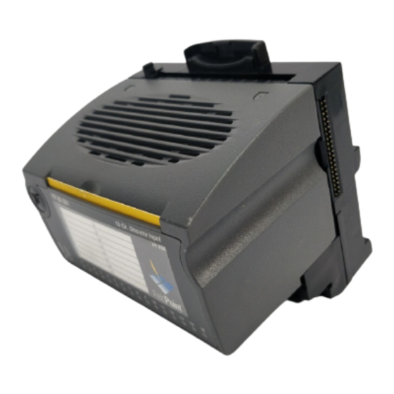
OPERATING INSTRUCTIONS
FP-DI-301
8-Channel, 24 V Discrete Input Module
These operating instructions describe the installation, features, and
characteristics of the FP-DI-301. For details on configuring and
accessing the FP-DI-301 over a network, refer to the user manual
for the particular FieldPoint network module you are using with
the FP-DI-301.
Features
The FP-DI-301 is a FieldPoint discrete input module with the
following features:
•
16 discrete input channels
•
Sinking inputs, compatible with 24 VDC sourcing outputs
•
On/Off LED indicators
•
Hot plug and play operation
•
3,000 V input to output isolation
•
Double insulated for 250 V safe working voltage
•
–40 to +70 °C operation
Installation
The FP-DI-301 mounts on a FieldPoint terminal base (FP-TB-xx)
unit. The hot plug and play operation of the FP-DI-301 allows you
to install it onto a powered terminal base without disturbing
the operation of other modules or terminal bases. The FP-DI-301
receives operating power from the terminal base.
FieldPoint ™ is a trademark of National Instruments Corporation. Product and company names
mentioned herein are trademarks or trade names of their respective companies.
321700B-01
© Copyright 1997, 1999 National Instruments Corp. All rights reserved. June 1999
Advertisement
Table of Contents

Related Manuals for National Instruments FieldPoint FP-DI-301


Summary of Contents for National Instruments FieldPoint FP-DI-301
- Page 1 The FP-DI-301 receives operating power from the terminal base. FieldPoint ™ is a trademark of National Instruments Corporation. Product and company names mentioned herein are trademarks or trade names of their respective companies.
- Page 2 To install the FP-DI-301, refer to Figure 1 and follow these steps: 1. Slide the terminal base key to either position X (used for any module) or position 5 (used for the FP-DI-301 module). 2. Align the FP-DI-301 alignment slots with the guide rails on the terminal base.
- Page 3 Figure 2. Basic Field Connections to Sourcing Output Devices Table 1 lists the terminal assignments for the signals associated with each channel. Table 1. Terminal Assignments Terminal Numbers Terminal Numbers V in V sup V in V sup Channel Channel © National Instruments Corp. FP-DI-301...
- Page 4 Discrete Input Circuit The inputs of the FP-DI-301 consist of optical isolators with current-limiting resistors. Each channel has one signal input, V which is referenced to the common, COM. When a voltage above the threshold voltage is applied to the V input of a channel, signal current flows through the input and turns on the optical isolator, registering as an ON condition.
- Page 5 • As with any hazardous voltage wiring, ensure that all wiring and connections meet with applicable electrical codes or common sense practices. Mount terminal bases in an area, © National Instruments Corp. FP-DI-301...
-
Page 6: Specifications
position, or cabinet that prevents accidental or unauthorized access to wiring with hazardous voltages. • The isolation of the FP-DI-301 is certified as double insulated for normal operating voltages of 250 Vrms. Do not use the FP-DI-301 as the sole isolating barrier between human contact and working voltages of more than 250 Vrms. - Page 7 Class A at 10 meters Mechanical Dimensions Figure 4 shows the mechanical dimensions of the FP-DI-301 installed onto a terminal base. Dimensions are given in inches [millimeters]. 4.22 [107.19] 4.31 [109.5] 3.60 [91.44] Figure 4. Mechanical Dimensions © National Instruments Corp. FP-DI-301...
Need help?
Do you have a question about the FieldPoint FP-DI-301 and is the answer not in the manual?
Questions and answers