Vega VEGAMIP R61 Operating Instructions Manual
Receiving unit
- transistor
Hide thumbs
Also See for VEGAMIP R61:
- Operating instructions manual (40 pages) ,
- Operating instructions manual (48 pages) ,
- Operating instructions manual (44 pages)

Related Manuals for Vega VEGAMIP R61


Summary of Contents for Vega VEGAMIP R61
-
Page 1: Operating Instructions
Operating Instructions VEGAMIP R61 Receiving unit - Transistor Document ID: 40694 Radar... -
Page 2: Table Of Contents
Technical data ......36 Dimensions ....... 40 VEGAMIP R61 • - Transistor... - Page 3 Safety instructions for Ex areas Please note the Ex-specific safety information for installation and operation in Ex areas. These safety instructions are part of the operating instructions manual and come with the Ex-approved instruments. Editing status: 2012-02-14 VEGAMIP R61 • - Transistor...
-
Page 4: About This Document
This symbol indicates special instructions for Ex applications. List The dot set in front indicates a list with no implied sequence. à Action This arrow indicates a single action. Sequence Numbers set in front indicate successive steps in a procedure. VEGAMIP R61 • - Transistor... -
Page 5: For Your Safety
Arbitrary conversions or modifications are explicitly forbidden. The safety approval markings and safety tips on the device must also be observed. VEGAMIP R61 • - Transistor... -
Page 6: Ce Conformity
2.5 CE conformity The device fulfills the legal requirements of the applicable EC guidelines. By affixing the CE marking, VEGA confirms successful testing of the product. Only with class A instruments: The device is a class A instrument designed for use in an industrial environment. -
Page 7: Environmental Instructions
The environment management system is certified according to DIN EN ISO 14001. Please help us fulfil this obligation by observing the environmental instructions in this manual: Chapter "Packaging, transport and storage" Chapter "Disposal" VEGAMIP R61 • - Transistor... -
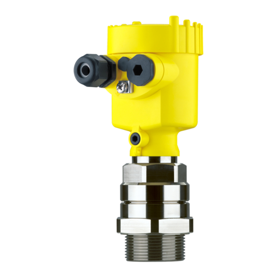
Page 8: Product Description
Operating instructions at the time of shipment (PDF) Order-specific sensor data for an electronics exchange (XML) Test certificate "Measuring Accuracy" (PDF) Go to www.vega.com, "Service" "VEGA Tools" and "serial number search". Scope of delivery The scope of delivery typically includes the following parts. - Page 9 The VEGAMIP 61 consists of the following components. Fig. 1: VEGAMIP 61 with plastic housing Emitting unit VEGAMIP T61 Receiving unit VEGAMIP R61 with control electronics Housing cover Housing with control electronics Process fitting VEGAMIP R61 • - Transistor...
-
Page 10: Packaging, Transport And Storage
Nonobservance of these instructions can cause damage to the device. Transport inspection The delivery must be checked for completeness and possible transit damage immediately at receipt. Ascertained transit damage or concealed defects must be appropriately dealt with. VEGAMIP R61 • - Transistor... -
Page 11: Accessories And Replacement Parts
You can find additional information in the supplementary instructions manual "Flanges according to DIN-EN-ASME-JIS" (Document-ID 31088). Electronics module The electronics module VEGAMIP R61 is a replacement part for microwave barriers of VEGAMIP series 60. You will find additional information in the following operating instructions manual: "Electronics module VEGAMIP R61 (receiving unit)"... - Page 12 The mounting adapter can only be used with the threaded version (internal horn antenna with PTFE cover). Fig. 3: VEGAMIP 61 with high temperature mounting adapter VEGAMIP R61 • - Transistor...
-
Page 13: Mounting
Avoid mounting the instrument too close to the vessel wall. Reflections from the vessel wall or from vessel installation can influence the switching accuracy. Fig. 4: Installation position (top view) VEGAMIP R61 • - Transistor... - Page 14 VEGAMIP 61 at a position in the vessel where no disturbances, e.g. from filling openings, agitators, etc., can occur. Non-metallic vessels Microwaves can penetrate non-conductive materials. Hence, it is possible to measure through the wall of non-conductive vessels. VEGAMIP R61 • - Transistor...
- Page 15 < 200 mm Glass or ceramic Inspection glass < 200 mm Aluminiumoxide ceramic Abrasion protection (ceramic) < 100 mm < 1000 mm Insulation material Mineral wool < 1000 mm Ceramic fibre plates < 500 mm Fireclay bricks VEGAMIP R61 • - Transistor...
- Page 16 Fig. 7: Installation in pipelines Min. distance 100 mm (3.94 in) Mount the threaded version of VEGAMIP 61 in the following way: Threaded version VEGAMIP R61 • - Transistor...
- Page 17 Hence, no counter nut is necessary for these versions. Buildup Avoid long sockets in which the medium can remain and if possible, mount VEGAMIP 61 front-flush. This applies mainly if buildup and dust are expected. VEGAMIP R61 • - Transistor...
- Page 18 Secure the filling material against falling out or turning. If using a fixing screw is technically not possible, you can secure the material in the socket with an adhesive. VEGAMIP R61 • - Transistor...
- Page 19 In this case, you have to use a window material which is appropriately resistant. In case of strong vessel vibrations, the VEGAMIP 61 should be Vibrations mounted with anti vibration blocks or rubber buffers. VEGAMIP R61 • - Transistor...
- Page 20 1000 mm, the two sensors must have an offset of max. 50 mm to each other. General rule: the bigger the antenna and the better it focusses, the more precise the orientation has to be. Fig. 12: Orientation of the sensors - Angle and offset VEGAMIP R61 • - Transistor...
- Page 21 In products with low dielectric value, we recommend using an instrument version with antenna extension because it focusses the signal optimally and has no signal loss. With instrument versions with detachable horn antenna, the antenna extension can be retrofitted. VEGAMIP R61 • - Transistor...
- Page 22 4 Mounting Fig. 14: Possibilities for signal deflection Metal plate for signal deflection of the microwave signal Bent antenna extension VEGAMIP R61 • - Transistor...
-
Page 23: Connecting To Power Supply
Unscrew the housing cover Loosen compression nut of the cable entry Remove approx. 10 cm (4 in) of the cable mantle, strip approx. 1 cm (0.4 in) of insulation from the ends of the individual wires VEGAMIP R61 • - Transistor... - Page 24 The terminal block is pluggable and can be removed from the electronics. To do this, lift the terminal block with a small screwdriver and pull it out. When inserting the terminal block again, you should hear it snap in. VEGAMIP R61 • - Transistor...
-
Page 25: Wiring Plan, Single Chamber Housing
Fig. 16: Wiring plan receiving unit - VEGAMIP 61 (receiver) - PNP action Voltage supply Load Connection - NPN action Fig. 17: Wiring plan receiving unit - VEGAMIP 61 (receiver) - NPN action Voltage supply Load VEGAMIP R61 • - Transistor... - Page 26 5 Connecting to power supply Connection - floating Fig. 18: Wiring plan receiving unit - VEGAMIP 61 (receiver) - floating Voltage supply Auxiliary voltage VEGAMIP R61 • - Transistor...
-
Page 27: Setup
The signal lamp signals the switching condition of the switching output. Control lamp (green) for indication of the instrument function (4) The green signal lamp (on) shows the operating state of the instrument as soon as voltage supply is connected correctly. VEGAMIP R61 • - Transistor... -
Page 28: Adjustment
The following function chart provides an overview of the switching conditions depending on the set mode and level. Level Switching status Signal lamp - Switching output (yellow) Mode max. closed Overflow protection Mode max. open Overflow protection Mode min. closed Dry run protection VEGAMIP R61 • - Transistor... - Page 29 The LED indication strip always shows a small section of the actual measuring range. Pressing the "<--" key makes the sensor more sensitive. Pressing the "-->" key makes the sensor less sensitive. VEGAMIP R61 • - Transistor...
- Page 30 The indication of the LED indication board does not change, but the instrument will become a little less sensitive with each pressing of the key. VEGAMIP R61 • - Transistor...
- Page 31 Hence, the VEGAMIP 61 switches very sensitive, even with relatively low covering by the product. Fig. 30: LED indication strip - Setting for products with low signal damping VEGAMIP R61 • - Transistor...
- Page 32 If possible, you can simulate a filling between emitting and receiving unit by using the hand or a metal sheet and check if the switching point is adjusted correctly. If the control lamp changes the switching condition, then the switching function is correct. VEGAMIP R61 • - Transistor...
-
Page 33: Maintenance And Fault Rectification
Signal lamp lights red Operating voltage too low Check operating voltage Electronics module has Exchange the instrument or send it in for repair detected an internal failure Instrument switches de- Check switching delay Adjust switching delay correctly layed VEGAMIP R61 • - Transistor... -
Page 34: Exchange Of The Electronics
Should these measures not be successful, please call in urgent cases 24 hour service hotline the VEGA service hotline under the phone no. +49 1805 858550. The hotline is also available outside the normal working hours on seven days a week around the clock. -
Page 35: Dismounting
Pass the instrument directly on to a specialised recycling company and do not use the municipal collecting points. These may be used only for privately used products according to the WEEE directive. VEGAMIP R61 • - Transistor... -
Page 36: Supplement
Instrument weight (depending on process fitting) Process fittings Pipe thread, cylindrical (ISO 228 T1) G1½ A 1½ NPT American pipe thread, tapered DIN from DN 50, ANSI from 2" Flanges G2 A or 2 NPT Mounting adapter VEGAMIP R61 • - Transistor... - Page 37 PP cover Outside the specified beam angle, the energy of the radar signal has a level of -3 dB (50 %) Not overload resistant and not short-circuit proof Note max. pressure of the process fitting VEGAMIP R61 • - Transistor...
- Page 38 20 … 55 V DC Operating voltage max. 0.8 W Power consumption Electrical protective measures IP 66/IP 67 Protection rating Overvoltage category Protection class Approvals Instruments with approvals can have different technical data depending on the version. VEGAMIP R61 • - Transistor...
- Page 39 9 Supplement That's why the associated approval documents have to be noted with these instruments. They are part of the delivery or can be downloaded under www.vega.com via "VEGA Tools" and "serial number search" as well as via "Downloads" and "Approvals".
-
Page 40: Dimensions
1½ NPT G1½ A Fig. 33: VEGAMIP 61 - threaded version Threaded version - internal horn antenna with PTFE cover - G1½ A Threaded version - internal horn antenna with PTFE cover - 1½ NPT VEGAMIP R61 • - Transistor... - Page 41 ø 44 mm (1.73") ø 75 mm (2.95") ø 115 mm (4.53") Fig. 34: VEGAMIP 61, encapsulated antennas Encapsulated horn antenna with PTFE cover - flange version Plastic encapsulated antenna with PP cover Mounting strap Adapter flange VEGAMIP R61 • - Transistor...
- Page 42 61 mm (2.4") Fig. 36: Mounting adapter with ceramic cover for VEGAMIP 61 - threaded version G2 A with PTFE cover (also with 2 NPT thread) 150 mm (5.9 in) or 300 mm (11.8 in) VEGAMIP R61 • - Transistor...
- Page 43 Les lignes de produits VEGA sont globalement protégées par des droits de propriété intellectuelle. Pour plus d'informations, on pourra se référer au site http://www.vega.com VEGA lineas de productos están protegidas por los derechos en el campo de la propiedad industrial. Para mayor información revise la pagina web http://www.vega.com Линии...
- Page 44 Horn antenna 42 Medium 14 Mode 28 Moisture 13 Mounting adapter 12, 42 Operation 27 Orientation of the sensor 20 Packaging 10 Pipelines 16 Polarisation direction 20 Potential equalisation 23 Receiving unit 9, 25, 27 VEGAMIP R61 • - Transistor...
- Page 45 Index VEGAMIP R61 • - Transistor...
- Page 46 Index VEGAMIP R61 • - Transistor...
- Page 47 Index VEGAMIP R61 • - Transistor...
- Page 48 All statements concerning scope of delivery, application, practical use and operating conditions of the sensors and processing systems correspond to the information avail- able at the time of printing. © VEGA Grieshaber KG, Schiltach/Germany 2012 40694-EN-120228 Subject to change without prior notice...
Need help?
Do you have a question about the VEGAMIP R61 and is the answer not in the manual?
Questions and answers