Table of Contents
Advertisement
Advertisement
Table of Contents

Related Manuals for Toro LDC-6


Summary of Contents for Toro LDC-6
- Page 1 OUTDOOR IRRIGATION CONTROLLER • LDC-6 • LDC-11 User Manual...
-
Page 2: Table Of Contents
TABLE OF CONTENTS Table of Contents Water Budgeting and Seasonal Adjustment Introduction Master Valve On/Off Selection The Controller Pump Delay Introduction to Programming Watering Schedules Station Delay Filling Out the Watering Installation Instructions Schedule Form Mounting the Controller Setting the Time and Date Electrical Wiring Setting the Time Wiring the Solenoid Valves... -
Page 3: Introduction
INTRODUCTION FEATURES The Toro Lawn Dial Outdoor Irrigation Controller is a programmable electronic timer that controls • Easy to install and program. the watering of six or eleven stations (depending • 6 individual Programs. on the model) using remote solenoid valves. -
Page 4: The Controller
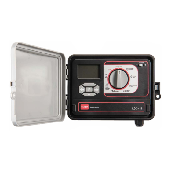
THE CONTROLLER The Controller has the following features, which will be explained in detail throughout this manual: • SET AUXILIARIES Control Dial - Rain Sensor used to select functions: turn on/off the rain sensor function • OFF - Main Valve/Pump Start stops irrigation - Pump Delay •... -
Page 5: Introduction To Programming Watering Schedules
INTRODUCTION TO PROGRAMMING WATERING SCHEDULES When programming the controller, there are the Programming is a lot easier if you first fill out a Watering Schedule Form, an example of which is following to consider: on the next page. You will have a record of your watering schedule and zone locations which can STATIONS OR ZONES be kept with your controller. -
Page 6: Filling Out The Watering Schedule Form
FILLING OUT WATERING SCHEDULE FORM VALVE NUMBER RUN TIME (minutes) In the area at the top of the form, fill in the area For each of the Programs and each of the and/or type of lawn or garden which is to be Stations, write in the Run Time required. -
Page 7: Setting The Time And Date
SETTING THE TIME AND DATE Control Switch SETTING THE TIME SETTING THE DATE Select Set Clock/Calendar on the Control Dial. Select Set Clock/Calendar on the Control Dial. This will cause the HOUR to flash. This will cause the HOUR to flash. Use the buttons to adjust the Press... -
Page 8: Setting Up Watering Programs
SETTING UP WATERING PROGRAMS Up to six Programs may be entered, each requiring the programming of: • Watering days – applied to all Station numbers and Start Times • Start times – up to six • Station numbers - up to four or six, depending on the model •... - Page 9 SETTING UP WATERING PROGRAMS To program Watering Days: Select SET WATERING DAYS on the Control Dial. One of three screens will appear. On the first screen, one of the days of the week will be flashing. On the second screen, may be replaced by EVEN.
-
Page 10: Suspending Automatic Watering
SETTING UP WATERING PROGRAMS SETTING STATION RUN TIMES The Station Run Time is the length of time the Station will water during the programmed watering cycle. Run times can be set from 0 (off) to 12 hours, 59 minutes, in one-minute increments. A Station is assigned to a Program when it is given a run time. -
Page 11: Manual Watering
MANUAL WATERING A single selected Station can be watered for a selected period of time. Select SYSTEM TEST RUN SINGLE STATION on the Control Dial. The Station Number will STATION flash. 1: 00 RUN TIME Use the buttons to select the Station to be run. -
Page 12: Running A System Test
RUNNING A TEST SYSTEM The system may be tested by setting selected stations to water for short times. For example, you might Station 2 to water for 2 minutes, or multiple Stations 1, 2 and 3 to water for 1 minute each To test a single Station: Select SYSTEM TEST... -
Page 13: Running A Program
RUNNING A PROGRAM To manually start a single Program or a number of Programs: PROG Select RUN PROG. on the Control Dial. A Program number will be displayed and will be flashing. Press to change to ON. Press to select another of the six programs and press to change to ON. -
Page 14: Rain Sensor
The Rain Sensor function requires the connection of an external rain sensor with “normally closed” con- tacts, such as the Toro Wired Rain Sensor (Product Code TRS). When sufficient rain is sensed, the relay contacts close, resulting in the suspension of the automatic watering programs. -
Page 15: Seasonal Adjustment
WATERING BUDGET AND SEASONAL ADJUSTMENT Changes in season and temperature generally require a change in watering run times to maintain a healthy landscape and conserve water. The season adjust feature enables you to change simultaneously, all programmed Run Times, in steps of 10%, from 10% of the programmed times up to 200%. -
Page 16: Master Valve On/Off Selection
MASTER VALVE ON/OFF SELECTION Most domestic irrigation systems operate from a town water system, or a bore or a dam (see Introduction). The irrigation controller has a Master Valve output which is used to control a Master Solenoid Valve when operating with a town water supply. The use of a Master Valve is highly recommended, particularly if the pipe connections to the Station Valves are done using PVC push on and clip connections which are prone to bursting open when continuously subjected to mains water pressure. -
Page 17: Station Delay
MASTER VALVE ON/OFF SELECTION Use the buttons to select the required Station STATION Press will flash. Press repeatedly until the required delay time is reached (1 to 99 seconds). Setting the time to 0 or 100 will reset the delay to OFF. SECS Press and the... -
Page 18: Installation Instructions
INSTALLATION INSTRUCTIONS MOUNTING THE CONTROLLER WIRING THE SOLENOID VALVES As the Controller comes with a 1.0m fixed power lead, select a location for the Controller within 0.9m of an outdoor electrical outlet. For safe, reliable operation, select an installation site which will provide the following conditions: •... -
Page 19: Rain Sensor
INSTALLATION INSTRUCTIONS RAIN SENSOR PUMP START RELAY CONNECTION The controller is factory fitted with a link be- CAUTION tween terminals R and C. If a Rain Sensor is not The controller cannot be used to power a to be used, then leave this link in place. pump motor directly. -
Page 20: Specification
SPECIFICATIONS Cabinet Dimensions 240mm x 80mm x 185mm Power Specifications Internal Transformer Input: IN: 230/240VAC 50Hz Output: OUT: 24VAC Max Station load 0.3A Total Master Valve Load 0.5A Total Maximum Load 0.8A Surge Protection 47KV normal mode Battery Type 9 volt Operating Temperature range 0-60 °... -
Page 21: Troubleshooting
TROUBLESHOOTING Symptom Possible Cause Remedy Fit a 9V battery and check that Mains power is not connected the controller is plugged in AND there is no 9V battery fitted to a power point and that it is (or it is flat). switched on. -
Page 22: Appendix A - Guidelines For Watering
All costs associated with the return of the product are the purchasers’ responsibility. To process the warranty, the retailer must contact Toro Australia via their representative or the phone number listed below. -
Page 23: Appendix B - Watering Schedule Planners
APPENDIX B - WATERING SCHEDULE PLANNERS VALVE NUMBER WATERING WATERING RUN TIME RUN TIME START TIME START TIME DAYS DAYS (minutes) (minutes) Start Time 1: Start Time 1: Start Time 2: Start Time 2: Start Time 3: Start Time 3: Start Time 4: Start Time 4: Start Time 5:... - Page 24 APPENDIX B - WATERING SCHEDULE PLANNERS VALVE NUMBER WATERING WATERING RUN TIME RUN TIME START TIME START TIME DAYS DAYS (minutes) (minutes) Start Time 1: Start Time 1: Start Time 2: Start Time 2: Start Time 3: Start Time 3: Start Time 4: Start Time 4: Start Time 5:...
- Page 25 APPENDIX B - WATERING SCHEDULE PLANNERS VALVE NUMBER WATERING WATERING RUN TIME RUN TIME START TIME START TIME DAYS DAYS (minutes) (minutes) Start Time 1: Start Time 1: Start Time 2: Start Time 2: Start Time 3: Start Time 3: Start Time 4: Start Time 4: Start Time 5:...
- Page 26 APPENDIX B - WATERING SCHEDULE PLANNERS VALVE NUMBER WATERING WATERING RUN TIME RUN TIME START TIME START TIME DAYS DAYS (minutes) (minutes) Start Time 1: Start Time 1: Start Time 2: Start Time 2: Start Time 3: Start Time 3: Start Time 4: Start Time 4: Start Time 5:...