
Related Manuals for Seitron CHEMIST 500


Summary of Contents for Seitron CHEMIST 500
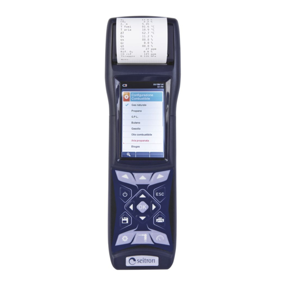
- Page 1 CHEMIST 500 Combustion Analyzer USE AND MAINTENANCE MANUAL Respect your environment: think before printing the full manual on paper...
- Page 2 SEITRON S.p.A. a socio unico - ALL RIGHTS RESERVED - Total or partial reproduction of this document by any means (including photocopying or storage on any electronic medium) and transmittal of same to third parties in any manner, even electronically, is strictly prohibited unless explicitly authorised in writing...
- Page 3 TABLE OF CONTENTS IMPORTANT INFORMATION Information about this manual Safety warnings SAFETY Intended use of the product Improper use of the product WORKING PRINCIPLE Working principle Measuring cells DESCRIPTION OF THE PRODUCT General Description of the Combustion Analyzer General Characteristics of the Combustion Analyzer Description of the Components of the Combustion Analyzer 4.3.1 Keypad...
- Page 4 TABLE OF CONTENTS POWER ON - OFF Starting the device CONFIGURATION Configuration Menu Analysis Menu 9.2.1 Configuration=>Analysis=>Fuel 9.2.2 Configuration=>Analysis=>Condensation 9.2.3 Configuration=>Analysis=>O reference 9.2.4 Configuration=>Analysis=>NO /NO ratio 9.2.5 Configuration=>Analysis=>Measurement units 9.2.6 Configuration=>Analysis=>Autozero 9.2.7 Configuration=>Analysis=>Measures list 9.2.8 Configuration=>Analysis=>Air temperature Instrument Menu 9.3.1 Configuration=>Instrument=>Bluetooth 9.3.2 Configuration=>Instrument=>Time/Date...
- Page 5 TABLE OF CONTENTS 11.0 PRINT 11.1 Print Menu 11.2 Print=>Report 11.3 Print=>Configuration 11.4 Print=>Test 11.5 Print=>Header 11.6 Print=>Printer 11.6.1 Print=>Printer=>Pairing 11.7 Print=>Measures list 12.0 MEASUREMENTS 12.1 Measurements Menu 12.2 Measurements=>Draft 12.3 Measurements=>Smoke 12.4 Measurements=>Ambient CO 12.5 Measurements=>Temperature 12.6 Measurements=>Pressure 12.7 Measurements=>Tightness test 12.7.1 Connection of the tool tightness test kit 12.8 Measurements=>Tightness test=>New piping (UNI 7129)
- Page 6 TABLE OF CONTENTS 13.2 Combustion Analysis - Preliminary operations 13.3 Combustion Analysis - Manual mode 13.4 Combustion Analysis - UNI 10389 mode 13.5 Combustion Analysis - BImSchV mode 13.6 Combustion Analysis - Data logger mode 14.0 SENSORS 14.1 Sensors arrangement 14.2 Sensor types and relevant positioning 14.3 Gas sensors life 14.4 Gas sensors life...
-
Page 7: Important Information
1.1 Information about this manual This manual describes the operation and the characteristics and the maintenance of the Combustion Analyzer Chemist 500. Read this operation and maintenance manual before using the device. The operator must be familiar with the manual and follow the instructions carefully. -
Page 8: Safety
This chapter describes the areas of application for which the CHEMIST 500 is intended. Using the CHEMIST 500 in other application areas is on the risk of the operator and the manufacturer assumes no responsibility and liability for loss, damage or costs which could be a result. It is mandatory to read and pay attention to the operating/maintenance manual. -
Page 9: Working Principle
WORKING PRINCIPLE 3.1 Working principle The gas sample is taken in through the gas probe, by a diaphragm suction pump inside the instrument. The measuring probe has a sliding cone that allows the probe to be inserted in holes with a diameter of 11 mm to 16 mm and to adjust the immersion depth: the gas picking point must be roughly in the centre of the flue section. -
Page 10: Measuring Cells
"CHEMIST 500" another 16 combustibles of which the chemical composition is known. The functions of "CHEMIST 500" include the storage and the average of the data acquired, the printing (on a roll of thermal polyester paper) of the results and the possibility of connecting the device to a computer to store to data via USB connection. -
Page 11: Pressure Sensor
Seitron does, however, certify measurement accuracy only when a calibration certificate has been issued by its own laboratory or by an authorised laboratory. - Page 12 4.3 Overview of Flue Gas Analyser Components LEGEND AUX connector (input for optional external probes) Keypad Display P connector- (negative input to measure draught) Cover for access to the printer to replace the roll IN connector (gas exhaust probe input by means of paper of a complete condensate separator unit) B-type USB connector to connect the device to...
-
Page 13: Keypad
4.3.1 Keypad Adhesive polyester keypad with preformed keys featuring main control functions: KEYS FUNCTION KEYS FUNCTION Activates the context keys shown on the Turns the device On/Off display Access to the Memory Exits the current screen menu Access to the Printing Select and/or Modify menu Access to the... -
Page 14: Printer
Backlight backlight turned with simultaneous pressure keys The backlight is turned on when any key is pressed, except ' ' key. 4.3.3 Printer Thermal on thermal polyester or thermal paper. Thermal polyester cannot be altered and it is resistant to light, to temperature, to humidity and to water. -
Page 15: Main Configurations
MAIN CONFIGURATIONS CHEMIST CHEMIST CHEMIST CHEMIST CHEMIST CHEMIST CHEMIST CHEMIST CHEMIST CHEMIST 502 B 502 C 503 B 504 N 504 S 500 X 500 XB O2 SENSOR CO+H2 SENSOR CO SENSOR CO SENSOR 0 .. 20000 ppm (2%) NO SENSOR NO2 SENSOR SO2 SENSOR EXPANDABLE... -
Page 16: Technical Specifications
TECHNICAL SPECIFICATIONS 6.1 Technical Specifications Autozero: Automatic autozero cycle. Dilution (where provided): Expansion system of the CO sensor measuring range up to 100.000ppm (10.00%) programmable as a simple protection of the CO sensor with triggering threshold programmable by the user. Preset triggering threshold at 1500 ppm. -
Page 17: Measurement And Accuracy Ranges
6.2 Measurement and Accuracy Ranges MEASUREMENT SENSOR RANGE RESOLUTION ACCURACY Electrochemical sensor 0 .. 25.0% vol 0.1% vol ±0.2% vol ±10 ppm 0 .. 200 ppm Electrochemical sensor 0 .. 8000 ppm 1 ppm ±5% measured value 201 .. 2000 ppm with H compensation ±10% measured value... -
Page 18: Preliminary Operations
Remove the instrument from its packing and check it for damage. Make sure that the content corresponds to the items ordered. If signs of tampering or damage are noticed, notify the SEITRON service centre or agent immediately and keep the original packing. A label at the rear of the analyser bears the serial number. This serial number should always be stated when requesting technical assistance, spare parts or clarification on the product or its use. -
Page 19: Checking And Replacing The Batteries
If battery charge appears to be low, let it discharge completely and then carry out a full 100% charge cycle by connecting the instrument to the power pack for 3 hours. If the problem persists, replace the battery pack with a SEITRON original or contact the SERVICE CENTRE to carry out the necessary repairs. -
Page 20: Connection Diagram
7.4 Connection diagram AA AL05 AAC TA03A AAC KP01 AA SA08 AA SF--A AAC SO01 K000000000SE 027384 010916... -
Page 21: Gas Sampling Probe
7.4.1 Gas sampling probe The gas sampling probe is made up of an INOX steel tube with a plastic hand grip and an internal K-type thermocouple (Ni-NiCr) for measuring the gas temperature up to 800°C. Flue gas temperature is measured by means of a thermocouple inserted in the tip of the probe. -
Page 22: Connecting The Tc-K Probe
7.4.4 Connecting the TcK probe Using the same input as for the K thermocouple "T1" (the same used for gas temperature), it is possible to measure the water delivery and return temperature by connecting some special probes. If temperature is taken on the pipe, it is suggested to use arc probes with a suitable diameter. -
Page 23: Power On - Off
POWER ON - OFF Starting the device 15/01/14 15/01/14 10:00 10:00 Combustion analysis Combustion analysis λ,n λ,n 1.25 1.25 T flue T flue 190.1 190.1 °C °C T air T air 15.4 15.4 °C °C Press and ΔT ΔT 74.7 74.7 °C hold for a... -
Page 24: Configuration
CONFIGURATION 9.1 Configuration menu 15/01/14 FUNCTION 10:00 Activate the context keys shown on the Configuration display. Returns to the previous screen. Analysis Instrument CONTEXT KEY FUNCTION Operator Alarms ◄ Selects the available parameters. Information Diagnostic Enters in the selected parameter setting. Language Restore ►... - Page 25 Configuration→Analysis → 15/01/14 FUNCTION 10:00 Activate the context keys shown on the Configuration display. Analysis Returns to the previous screen. Fuel Condensation CONTEXT KEY FUNCTION reference /NO ratio ◄ Selects the available parameters. Measure units Autozero Enters in the selected parameter setting. Measures list Air temp.
-
Page 26: Configuration=>Analysis=>Fuel
9.2.1 Configuration→Analysis→Fuel → 15/01/14 15/01/14 10:00 10:00 Configuration Configuration Fuel Fuel Natural gas Pellet 8% Propane Wood 20% L.P.G. Woodchips Butane Coal Diesel oil Olive pits Fuel oil Propane-Air Biogas FUNCTION Activate the context keys shown on the display. The arrows select each line displayed. Confirms the choice of fuel to be used during the analysis. -
Page 27: Configuration=>Analysis=>Condensation
9.2.2 Configuration→Analysis→Condensation → 15/01/14 10:00 Configuration Condensation Altitude Altitude above sea level R.H. air Relative humidity of air FUNCTION Activate the context keys shown on the display. The arrows select each line displayed (the selected line is red). In edit mode, it scrolls through the suggested values. Enters the modify mode for the selected parameter, then confirms the modification. - Page 28 9.2.3 Configuration→Analysis→Reference O → 15/01/14 10:00 Configuration reference Percentage of Oxygen in CO measurement Percentage of Oxygen in NO measurement Percentage of Oxygen in SO measurement FUNCTION Activate the context keys shown on the display. Keys '▲' and '▼' select any line shown on the display (the selected line is evidenced in red).
- Page 29 9.2.4 Configuration→Analysis→NO /NO ratio → 15/01/14 10:00 Configuration /NO ratio 1.05 FUNCTION Activate the context keys shown on the display. When in modify mode, sets the desired value. Enters edit mode of the selected element and then confirms the change. When pressed in modify mode cancels the selection made, otherwise returns to the previous screen.
-
Page 30: Configuration=>Analysis=>Measurement Units
9.2.5 Configuration→Analysis→Measurement units → 15/01/14 10:00 Configuration Measure units Measurement unit can be set as: ppm - mg/m - mg/kWh - g/GJ - g/m - g/kWh - % Measurement unit can be set as: ppm - mg/m - mg/kWh - g/GJ - g/m - g/kWh - % Measurement unit can be set as: ppm - mg/m - mg/kWh - g/GJ - g/m... -
Page 31: Configuration=>Analysis=>Autozero
9.2.6 Configuration→Analysis→Autozero → 15/01/14 10:00 Configuration Autozero Autozero Duration of autozero, expressed in seconds. Purging Duration of the cleaning cycle, expressed in seconds. FUNCTION Activate the context keys shown on the display. When in modify mode, sets the desired value. Enters edit mode of the selected element and then confirms the change. -
Page 32: Configuration=>Analysis=>Measures List
9.2.7 Configuration→Analysis→Measures list → 15/01/14 10:00 Configuration Measures list λ,n T flue T air ΔT Qs (PCI) ηs (PCI) » FUNCTION Activate the context keys shown on the display. Select each line displayed (the line selected is red). In edit mode, it sets the desired value. When pressed in modify mode cancels the selection made, otherwise returns to the previous screen. - Page 33 Example: → 1. Add a measurement to the list - example 15/01/14 15/01/14 15/01/14 15/01/14 10:00 10:00 10:00 10:00 Configuration Configuration Configuration Configuration Measures list Measures list Measures list Measures list λ,n λ,n ▲ T flue T flue λ,n λ,n T air T air T flue...
- Page 34 9.2.8 Configuration→Analysis→Air temperatur → 15/01/14 10:00 Configuration Air temperature Probe T 25.0 °C Air T ----- °C FUNCTION Activate the context keys shown on the display. When in modify mode, sets the desired value. Activates the context key located in the left side of the display. Returns to the previous screen without saving the changes made.
- Page 35 Configuration→Instrument → 15/01/14 FUNCTION 10:00 Activate the context keys shown on the Configuration Instrument display. Returns to the previous screen. Bluetooth Time/Date Brightness Pump CONTEXT KEY FUNCTION ◄ Selects the available parameters. CO dilutor Micromanometer Enters in the selected parameter setting. ►...
-
Page 36: Configuration=>Instrument=>Bluetooth
15/01/14 10:00 Bluetooth Bluetooth enabling / disabling Status Instrument name CHEMIST 500 - 0001 MAC address detected 00026BB5500 FUNCTION Activate the context keys shown on the display. Also activates the context key shown on the display. Returns to the previous screen. -
Page 37: Configuration=>Instrument=>Time/Date
9.3.2 Configuration→Instrument→Time/Date → 15/01/14 10:00 Configuration Time/Date Time, in the chosen format Time 14:00 Date Date, in the chosen format 15/01/14 Date format: EU (Europe) or USA (America) Mode Mode Time format: 24h or 12h FUNCTION Activate the context keys shown on the display. When in modify mode, sets the desired value. -
Page 38: Configuration=>Instrument=>Brightness
9.3.3 Configuration→Instrument→Brightness → 15/01/14 10:00 Configuration Brightness FUNCTION Activate the context keys shown on the display. Increases or decreases the brightness of the display. Confirms the modification. When pressed in modify mode cancels the selection made, otherwise returns to the previous screen. CONTEXT KEY FUNCTION ◄... -
Page 39: Configuration=>Instrument=>Pump
9.3.4 Configuration→Instrument→Pump → 15/01/14 10:00 Configuration Pump Pump Flow Displays the flow of the pump, expressed in litres per minute. l/min FUNCTION Activate the context keys shown on the display. When in modify mode, sets the desired value. Enters edit mode of the selected element and then confirms the change. When pressed in modify mode cancels the selection made, otherwise returns to the previous screen. -
Page 40: Configuration=>Instrument=>Co Dilutor
9.3.5 Configuration→Instrument→CO dilutor → 15/01/14 10:00 Configuration CO dilutor Available settings: auto, on or off Mode auto Limit Threshold that activates the dilution pump (available only if the "Mode" parameter is set o 4000 "auto". FUNCTION Activate the context keys shown on the display. Select each line displayed (the line selected is red). -
Page 41: Configuration=>Instrument=>Micromanometer
9.3.6 Configuration→Instrument→Micromanometer → 15/01/14 10:00 Configuration Micromanometer Sets the input used for the test: P+ o P- Inlet FUNCTION Activate the context keys shown on the display. In edit mode, it sets the desired input. Enters edit mode of the selected element and then confirms the change. When pressed in modify mode cancels the selection made, otherwise returns to the previous screen. -
Page 42: Configuration=>Operator
Configuration→Operator → 15/01/14 10:00 Configuration Operator Operator 1 Operator 2 Operator 3 Operator 4 Operator 5 Operator 6 Operator 7 Operator 8 FUNCTION Activate the context keys shown on the display. In "edit text": Moves the cursor on the box corresponding to the letter or number required to form the word. - Page 43 Example: → 1. Edit text 15/01/14 15/01/14 15/01/14 10:00 10:00 10:00 Configuration Edit text Edit text Operator Operator 1 Operator 2 Operator 3 Operator 1_ Operator _ Operator 4 Operator 5 Operator 6 Operator 7 Operator 8 15/01/14 15/01/14 15/01/14 10:00 10:00 10:00...
-
Page 44: Configuration=>Alarm
Configuration→Alarm → 15/01/14 10:00 Configuration Alarms Number of the alarm set Number Monitored parameter: O - CO - NO - NO - P diff - Plow - P ext - T1 - T2 Measure Type of alarm set: massimo - minimo - spento Mode maximum Threshold setting for the alarm: ±999999.999... - Page 45 Configuration→Information → 15/01/14 FUNCTION 10:00 Activate the context keys shown on the Information display. Returns to the previous screen. Battery Sensors InfoService Reminder CONTEXT KEY FUNCTION ◄ Selects the available parameters. Probes Enters in the selected parameter setting. ► Selects the available parameters. PARAMETER DESCRIPTION Displays the state of charge of the internal battery.
-
Page 46: Configuration=>Information=>Battery
9.6.1 Configuration→Information→Battery → 15/01/14 10:00 Information Battery 94 % FUNCTION Activate the context keys shown on the display. Returns to the previous screen. CONTEXT KEY FUNCTION Returns to the previous screen. K000000000SE 027384 010916... -
Page 47: Configuration=>Information=>Sensors
9.6.2 Configuration→Information→Sensor → 15/01/14 15/01/14 10:00 10:00 Information Diagnostic Sensors Sensors S1: O S2: CO S3: NO For further information, see section 9.7.1. S4: NO FUNCTION Activate the context keys shown on the display. Returns to the previous screen. CONTEXT KEY FUNCTION Displays the details of the main features of the sensors installed. -
Page 48: Configuration=>Information=>Infoservice
15/01/14 10:00 10:00 10:00 Information Information Information Service Service Service Seitron S.p.A. Model Chemist 500 X Bootloader version 1.02 Via M. Prosdocimo, 30 Serial number 9999 Protocol number 000001 Bassano del Grappa, VI Firmware version 9.99 0x2765 Tel. 0424 567842... -
Page 49: Configuration=>Information=>Reminder
9.6.4 Configuration→Information→Reminder → 15/01/14 10:00 Password Reminder 0 0 0 0 FUNCTION Activate the context keys shown on the display. Sets the password. The password is: 1111. Returns to the previous screen. CONTEXT KEY FUNCTION Confirm password and enter the menu “Reminder”. Returns to the previous screen. -
Page 50: Configuration=>Information=>Probes
9.6.5 Configuration→Information→Probe → 15/01/14 10:00 FUNCTION Information Probes Activate the context keys shown on the display. Micromanometer int. 1039 External probe ---- Returns to the previous screen. CONTEXT KEY FUNCTION Returns to the previous screen. K000000000SE 027384 010916... -
Page 51: Configuration=>Diagnostic
Configuration→Diagnostic → 15/01/14 FUNCTION 10:00 Activate the context keys shown on the Diagnostic display. Returns to the previous screen. Sensors Gas probe Hardware Pump CONTEXT KEY FUNCTION ◄ Selects the available parameters. On site cal. Enters in the selected parameter setting. ►... -
Page 52: Configuration=>Diagnostic=>Sensors
9.7.1 Configuration→Diagnostic→Sensors → 15/01/14 10:00 Diagnostic Sensors S1: O S2: CO S3: NO S4: NO FUNCTION Activate the context keys shown on the display. Selects the fuel. Activates the context keys located in the left side of the display. Returns to the previous screen. CONTEXT KEY FUNCTION Displays the details of the selecter sensor (see example below). -
Page 53: Configuration=>Diagnostic=>Gas Probe
9.7.2 Configuration→Diagnostic→Gas probe → 15/01/14 10:00 Diagnostic Connect the flue gas sampling probe and filter unit assembly to the Gas probe instrument; Close the flue gas probe Fully insert the black rubber cap on the gas probe tip, as shown in the following picture: Press OK to start Black rubber cap... - Page 54 9.7.3 Configuratione→Diagnostic→Hardware → 15/01/14 10:00 Diagnostic Hardware State of memory. Memories State of calibration. Calibration Version of CPU board HW Cpu version Version of motherboard HW MB version FUNCTION Activate the context keys shown on the display. Returns to the previous screen. CONTEXT KEY FUNCTION Returns to the previous screen.
-
Page 55: Configuration=>Diagnostic=>Pump
9.7.4 Configuration→Diagnostic→Pump → 15/01/14 10:00 Diagnostic Pump Pump Flow l/min FUNCTION Activate the context keys shown on the display. In edit mode, cycling between on and off. Enters edit mode of the selected element and then confirms the change. Returns to the previous screen. CONTEXT KEY FUNCTION Enters edit mode: it is possible to turn the gas suction pump on and off. - Page 56 9.7.5 Configuration→Diagnostic→On site cal. → 15/01/14 10:00 Password On site calibration 0 0 0 0 FUNCTION Activate the context keys shown on the display. Sets the password. Selects line; the selected line is evidenced in red. In modification sets the value or the desired mode. Activates the context key located in the left side of the display.
-
Page 57: Calibration Procedure
→ Calibration procedure To carry on the recalibration the following instruments are needed: - Known concentration gas cylinder suitable for the sensor, complete with a pressure regulator - Flow meter - Hose with Tee fitting to connect the cylinder to the flowmeter and to the instrument In the following is described a recalibration example for the CO sensor. - Page 58 → 3. Once in the ‘On site calibration’ menu, is shown the list of the installed sensors for which the recalibration is available. In the recalibration screen all information related to the last performed calibration is shown, as well as the relevant values. Calibrate: saves new calibration 15/01/14...
- Page 59 → • The calibration will be possible only when the status is set to '----' or 'inactive'. 15/01/14 15/01/14 15/01/14 10:00 10:00 10:00 On site calibration On site calibration On site calibration Sensor CO Sensor CO Sensor CO Calibrate Calibrate Calibrate Status Status...
- Page 60 → • After the stabilization time, select 'Calibrate' and activate the function ' ' to store the new calibration. 15/01/14 15/01/14 10:00 10:00 Messages in the 'Status' line: On site calibration On site calibration saving: instrument saving Sensor CO Sensor CO performed calibration Calibrate Calibrate...
-
Page 61: Configuration=>Language
Configuratione→Language 15/01/14 10:00 Configuration Language Italiano English Français Espaňol Deutsch Русский FUNCTION Activate the context keys shown on the display. Scrolls through the available languages. Sets the selected language. Returns to the previous screen. CONTEXT KEY FUNCTION Sets the selected language. K000000000SE 027384 010916... -
Page 62: Configuration=>Restore
Configuration→Restore 15/01/14 15/01/14 10:00 10:00 Configuration Configuration Restore Restore WARNING Clear memory data and Confirm restoring? restore factory setting? F1: restore F2: cancel di fabbrica? FUNCTION Activate the context keys shown on the display. Starts the factory data reset phase. Exits the current screen without resetting. -
Page 63: Memory
10.0 MEMORY 10.1 Memory Menu 15/01/14 FUNCTION 10:00 Activate the context keys shown on the Memory display. Returns to the previous screen. Save Average CONTEXT KEY FUNCTION Select Data logger ◄ Selects the available parameters. Delete Usage % Enters in the selected parameter setting. ►... - Page 64 Warning: in automatic mode, the measurements of carbon black, draught and ambient CO must be taken before starting the combustion analysis. Manual analysis mode If the user chooses the manual mode, he will perform the combustion analysis manually; in this case, the settings regarding printing and duration of the automatic analysis will not be considered.
-
Page 65: Memory Organization
10.1.1 Memory Organization K000000000SE 027384 010916... -
Page 66: Memory=>Save
10.2 Memory Menu→Save 15/01/14 15/01/14 10:00 10:00 Memory Memory Save Save Manual analysis mode Automatic analysis mode Mode Mode manual UNI 10389 Memory Number of selected memory Memory Number of selected memory Number of analyses carried Number of samples to take Analysis Samples Interval... - Page 67 Example 1: Saving the combustion analysis in manual mode 15/01/14 15/01/14 15/01/14 10:00 10:00 10:00 Memory Memory Memory Save Save Save Mode manual Mode manual Mode manual Memory Memory Memory Analysis Analysis Analysis Example 2: Saving the combustion analysis in automatic mode (example UNI 10389) 15/01/14 15/01/14 15/01/14...
-
Page 68: Memory=>Average
10.3 Memory Menu→Average 15/01/14 10:00 Memory Average analysis λ,n 1.25 T flue 190.1 °C T air 15.4 °C ΔT 74.7 °C ηs 91.4 FUNCTION Activate the context keys shown on the display. Scrolls through the values of the average analysis. Activates the context key located in the left side of the display. -
Page 69: Memory=>Select
Boiler model Memory Boiler xxxx Customer Customer Address A d d r e s s t h e Seitron customer A d d r e s s t h e Address Via M. Prosdocimo customer n° 30 Bassano del Grappa Phone... - Page 70 15/01/14 15/01/14 10:00 10:00 Memory Memory Select Recall Memory Measure conditions Customer Single analysis Seitron Address Via M. Prosdocimo Average analysis n° 30 Bassano del Grappa Phone 0424 567842 Boiler xxxx Date 15/01/14 FUNCTION Activate the context keys shown on the display.
- Page 71 2. Details of Single analysis 15/01/14 15/01/14 10:00 10:00 Memory Memory Single analysis Average analysis 15/01/14 15:10:30 15/01/14 15:15:00 λ,n 15/01/14 15:20:30 1.25 T flue 15/01/14 15:25:00 190.1 °C T air 15/01/14 15:30:35 15.4 °C ΔT 74.7 °C ηs 91.4 ▲...
- Page 72 3. Average interval details 15/01/14 15/01/14 10:00 10:00 Memory Memory Defines the starting sample to define the analysis Average Average analysis average. Defines the end sample to define the analysis λ,n average. 1.25 T flue 190.1 °C T air 15.4 °C ΔT 74.7...
-
Page 73: Memory=>Data Logger
10.5 Memory Menu→Data logger 15/01/14 10:00 Memory Data logger The selectable analysis modes are: manual - UNI 10389 - BImSchV - data logger Mode UNI 10389 Samples Number of samples to make (parameter not visible in manual analysis mode). Interval Period of acquisition of each sample (parameter not visible in manual analysis mode). -
Page 74: Memory=>Delete
10.6 Memory→Delete 15/01/14 FUNCTION 10:00 Activate the context keys shown on the Memory display. Delete Returns to the previous screen. Single CONTEXT KEY FUNCTION ◄ Selects the available parameters. Enters in the selected parameter setting. ► Selects the available parameters. PARAMETER DESCRIPTION This option allows the user to delete the contents of each individual memory;... -
Page 75: Memory=>Delete=>Single
10:00 Memory Memory Delete single Delete single Memory number Memory Memory Customer Customer Customer Seitron Seitron WARNING Address of the Address Via M. Prosdocimo Address Via M. Prosdocimo Confirm deleting? customer n° 30 n° 30 F1: Delete Bassano del Grappa... -
Page 76: Memory=>Delete=>All
10.6.2 Memory→Delete→All 15/01/14 15/01/14 10:00 10:00 Memory Memory Delete all Delete all WARNING Confirm deleting? Delete all data? F1: Delete F2: cancel FUNCTION Activate the context keys shown on the display. Start erasing all memories. Returns to the previous screen. CONTEXT KEY FUNCTION Start erasing all memories. -
Page 77: Memory=>Usage
10.7 Memory→Usage % 15/01/14 10:00 Memory Usage % FUNCTION Activate the context keys shown on the display. Returns to the previous screen. CONTEXT KEY FUNCTION Returns to the previous screen. K000000000SE 027384 010916... -
Page 78: Print
11.0 PRINT 11.1 Print FUNCTION Activate the context keys shown on the display. Returns to the previous screen. CONTEXT KEY FUNCTION ◄ Selects the available parameters. Enters in the selected parameter setting. ► Selects the available parameters. PARAMETER DESCRIPTION Enables the Print Menu. Allows to print the combustion analysis data on a paper ticket which reports the measurement values. -
Page 79: Print=>Report
11.2 Print→Report 15/01/14 15/01/14 Date: 15/01/14 10:00 10:00 Time: 10.10 Fuel: Natural gas Altitude: 0 m Print Print R.H. air: 50 % Report Report 4.2 ٪ 9.3 ٪ Analysis running Analysis running λ,n 1.25 T flue 190.2 °C Copies Copies WARNING T air 15.4 °C... -
Page 80: Print=>Configuration
11.3 Print→Configuration 15/01/14 10:00 Print Configuration Set the number of copies to print: 1 .. 5. Copies The test ticket models that can be selected are: partial - full - total Report partial Date/Time manual Set between: Manual: date and time are not printed on the analysis report. Auto: date and time are printed automatically on the analysis report. -
Page 81: Print=>Test
11.4 Print→Test 15/01/14 10:00 Print Test Print Paper feed FUNCTION Activate the context keys shown on the display. Selects line; the selected line is evidenced in red. In modification sets the value or the desired mode. Activates the context key located in the left side of the display. Returns to the previous screen. -
Page 82: Print=>Header
11.5 Print→Header 15/01/14 10:00 Print Header Line 1 ---- Line 2 ---- Line 3 ---- Line 4 ---- Line 5 ---- Line 6 ---- FUNCTION Activate the context keys shown on the display. In "edit text": It moves the cursor on the box corresponding to the letter or number required to form the desired word. - Page 83 Example: 1. Edit text 15/01/14 15/01/14 15/01/14 10:00 10:00 10:00 Print Edit text Edit text Header Line 1 ---- Line 2 ---- Line 3 ---- Operator 1_ Operator 1_ Line 4 ---- Line 5 ---- Line 6 ---- 15/01/14 15/01/14 15/01/14 10:00 10:00...
-
Page 84: Print=>Printer
11.6 Print→Printer 15/01/14 15/01/14 10:00 10:00 Print Print Printer Printer Printer type: built in (internal) - Bluetooth (external). Type Type built in Bluetooth Name of the Bluetooth printer associated with the ---- instrument. ---- Address of the Bluetooth printer associated with the instrument. - Page 85 11.6.1 Print→Pairing 15/01/14 10:00 Print Configuration Report Pairing Printer Header Measures list FUNCTION Activate the context keys shown on the display. Selects line; the selected line is evidenced in red. In modification sets the value or the desired mode. Activates the context key located in the left side of the display. Returns to the previous screen.
- Page 86 1. Once the Bluetooth printer is configured, proceed as follows: 15/01/14 15/01/14 15/01/14 10:00 10:00 10:00 Print Print Print Pairing Pairing SPP-R200 Select icon 'Pairing' to start configuration MPT-II Configuration WARNING Report Turn on the printer and start searching Pairing Printer F1: search F2: esc...
-
Page 87: Print=>Measures List
11.7 Print→Measures list 15/01/14 10:00 Configuration Measures list λ,n T flue T air ΔT Qs (PCI) ηs (PCI) » FUNCTION Activate the context keys shown on the display. Selects the available measurements from the suggested list. In edit mode, it scrolls through the measurements present. Confirms the modification. - Page 88 Example: 1. Add a measurement to the list 15/01/14 15/01/14 15/01/14 15/01/14 10:00 10:00 10:00 10:00 Configuration Configuration Configuration Configuration Measures list Measures list Measures list Measures list ▼ λ,n λ,n T flue T flue λ,n λ,n ▲ T air T air T flue T flue...
-
Page 89: Measurements
12.0 MEASUREMENTS 12.1 MEASUREMENTS 15/01/14 FUNCTION 10:00 Activate the context keys shown on the Measurements display. Returns to the previous screen. Draft Smoke CONTEXT KEY FUNCTION Ambient CO Temperature ◄ Selects the available parameters. Pressure Tightness test Enters in the selected parameter setting. Leak detector Aux Meas. - Page 90 Pressure SEE SECTION 12.6. According to the version, CHEMIST 500 can perform the tightness test on heating plants which use combustible gases according to the standards UNI 7129-1: 2015 and UNI 11137: 2012, respectively applicable to new or renewed pipings and to existing pipings, or according to the German standard DVGW TRGI 2008.
-
Page 91: Measurements=>Draft
12.2 Measurements→Draught 04/03/16 04/03/16 04/03/16 10:00 10:00 10:00 Measurements Measurements Measurements Draft UNI 10845 Draft UNI 10845 Draft UNI 10845 P diff P+ low P+ ext T outdoor T outdoor T outdoor °C °C °C P diff ref P diff ref P diff ref To measure the draught proceed as follows: - Connect the probe pressure input hose to the instrument P- input. -
Page 92: Measurements=>Smoke
12.3 Measurements→Smoke 15/01/14 10:00 Measurements Smoke Measure 1 Measure 2 Measure 3 Average - Measure the carbon black using the specific optional kit. - Enter the values found. - The values of the carbon black that you want to save must be acquired before saving the analyses. - To join the values of the carbon black to the measurements of the current analysis use the ' ' function. -
Page 93: Measurements=>Ambient Co
12.4 Measurements→Ambient CO 15/01/14 10:00 Measurements Ambient CO CO max It is compulsory to perform the autozero in the clean air, so that the ambient CO measurement is correct. It is advisable to turn on the instrument and wait for the autozero completion outside the area where the test is being performed. -
Page 94: Measurements=>Temperature
12.5 Measurements→Temperature 15/01/14 15/01/14 10:00 10:00 Measurements Measurements Temperature Temperature T1 flow T1 flow 70.5 °C T2 return ΔT 45.2 °C °C ΔT 25.3 °C ΔT FUNCTION Activate the context keys shown on the display. Returns to the previous screen. CONTEXT KEY FUNCTION Accesses the acquisition of the temperature difference between the supply... -
Page 95: Measurements=>Pressure
12.6 Measurements→Pressure 15/01/14 15/01/14 10:00 10:00 Measurements Measurements Pressure Pressure Measurement Measurement differential pressure by pressure by means of P diff P ext means of the internal external draught 0.01 0.01 pressure sensor. gauge. FUNCTION Activate the context keys shown on the display. Returns to the previous screen. -
Page 96: Measurements=>Tightness Test
12.7 Measurements→Tightness test Tightness test according UNI 7129-1: 2015 and Tightness test according DVGW TRGI (when the UNI 11137: 2012 (when the instrument version so instrument version so provides). provides). 15/01/14 15/01/14 10:00 10:00 Tightness test Tightness test TRGI Existing Gas meter Result Result... - Page 97 12.7.1 Connecting the tightness test kit to the instrument. K000000000SE 027384 010916...
- Page 98 12.8 NEW PIPING: UNI 7129-1: 2015 STANDARD (when the instrument version so provides) 15/01/14 10:00 UNI 7129 Configuration Stabilization Duration of the stabilisation phase that can be set between 15 and 240 minutes Printing mode, that can be set as manual or automatic. Print auto Volume input mode can be set as 'manual' or 'default'.
- Page 99 If you use volume calculation, for each section of piping it is necessary to set the material, the nominal diameter and the length of the same. CHEMIST 500 calculates the volume of the section ("partial volume") and it adds it up, activating the context key ' ' (sum piping), to the calculation of the volume of the system.
- Page 100 tightness test by pressing the key relative to the context key ' ', which starts the stabilisation phase. In the stabilisation screen, the following values are displayed: Actual pressure measured by the instrument, in the selected measurement unit. ∆P1': Pressure variation in the last minute, updated every 10 seconds. This value gives a rough indication about the stabilization level reached in the piping system.
-
Page 101: Configuration Of Tightness Test According To Uni 7129
12.8.1 CONFIGURATION OF TIGHTNESS TEST ACCORDING TO UNI 7129-1: 2015 15/01/14 15/01/14 15/01/14 10:00 10:00 10:00 UNI 7129 UNI 7129 UNI 7129 Configuration Configuration Configuration Stabilization Stabilization Stabilization Print Print Print manual manual manual Volume setup default Volume setup default Volume setup default Volume... - Page 102 15/01/14 15/01/14 15/01/14 10:00 10:00 10:00 UNI 7129 UNI 7129 UNI 7129 Configuration Configuration Configuration Stabilization Stabilization Stabilization Print Print Print auto auto auto Volume setup Volume setup Volume setup default manual manual Volume Volume Volume <100 18.0 18.0 Measure volume Measure volume Calcolate volume Calcolate volume...
- Page 103 Take, with the syringe (that comes with the tightness test kit), 100 ml of gas. If the volume measuring procedure of the system ends correctly, CHEMIST 500 automatically displays the measured volume, otherwise it requires another test. 15/01/14 15/01/14 10:00...
- Page 104 15/01/14 15/01/14 10:00 10:00 UNI 7129 UNI 7129 Configuration Calculate volume Stabilization Volume 19.2 Print auto Fuel L.P.G. Partial Test gas Starts the Material Type test completa Steel tightness test Volume Diameter 18.0 3/8" (see Lenght Measure volume section 10.0 12.9.2).
-
Page 105: Performing Tightness Test According To Uni 7129
12.8.2 PERFORMING TIGHTNESS TEST ACCORDING TO UNI 7129 Wait for 15/01/14 15/01/14 15/01/14 10:00 10:00 10:00 the end of the autozero UNI 7129 UNI 7129 UNI 7129 Pressurization Pressurization Pressurization pressurize the P diff P diff P diff system WARNING 0.06 Fill the system to The pressure of... - Page 106 Print Report Oper.: John Smith Sign.: ______________ Analysis Running Test according to Model Tightness test WARNING UNI 7129-1 CHEMIST 500 Printing. Serial: 999989 Please wait... Date: 15/01/14 F1: stop Time: 10.30 Stab. duration:00:15:00 Test duration: 00:05:00 V pip 25.0 dm 10.05 hPa...
- Page 107 12.9 EXISTING PIPING: UNI 11137: 2012 STANDARD (when the instrument version so provides) 15/01/14 10:00 UNI 11137 Configuration Stabilization Duration of the stabilisation phase that can be set between 1 and 240 minutes. Printing mode, that can be set as manual or automatic. Print auto Fuel used in the system: L.P.G.
- Page 108 If you use volume calculation, for each section of piping it is necessary to set the material, the nominal diameter and the length of the same. CHEMIST 500 calculates the volume of the section ("partial volume") and it adds it up, activating the context key ' ' (sum piping), to the calculation of the volume of the system.
- Page 109 Press the key relative to the context key ' Open the valve on the side where the syringe is connected, take exactly 100 ml (100 cc) of the gas present in the system. Wait for the stabilisation of the pressure of the system. After a few seconds, the device displays the measured volume.
- Page 110 ∆P: Pressure variation between the last instant and the first instant of the test. If the pressure decreased, it presents a negative value. Qtest: Is the calculated leakage measured in dm /h according to the conditions under which the test has been performed, i.e.
-
Page 111: Configuration Of Tightness Test According To Uni 11137
12.9.1 CONFIGURATION OF TIGHTNESS TEST ACCORDING TO UNI 11137 15/01/14 15/01/14 15/01/14 10:00 10:00 10:00 UNI 11137 UNI 11137 UNI 11137 Configuration Configuration Configuration Stabilization Stabilization Stabilization Print Print Print manual manual manual Fuel L.P.G. Fuel L.P.G. Fuel L.P.G. Test gas Test gas Test gas Type test... - Page 112 15/01/14 15/01/14 15/01/14 10:00 10:00 10:00 UNI 11137 UNI 11137 UNI 11137 Configuration Configuration Configuration Stabilization Stabilization Stabilization Print Print Print manual manual manual Fuel L.P.G. Fuel L.P.G. Fuel L.P.G. Test gas Test gas Test gas Fuel Type test Type test Type test preliminary preliminary...
- Page 113 Alternatively Take, with the syringe (that comes with the tightness test kit), 100 ml of gas. If the volume measuring procedure of the system ends correctly, CHEMIST 500 automatically displays the measured volume, otherwise it requires another test. 15/01/14 15/01/14...
- Page 114 15/01/14 15/01/14 10:00 10:00 UNI 11137 UNI 11137 Configuration Calculate volume Stabilization Volume Total volume acquired. 18.0 Print auto Fuel L.P.G. Partial Volume of the section of piping set below. Test gas Sets the material of the section of piping. Type test Material completa...
- Page 115 12.9.2 PERFORMING THE TIGHTNESS TEST ACCORDING TO UNI 11137 Wait for 15/01/14 15/01/14 15/01/14 10:00 10:00 10:00 the end of the autozero UNI 11137 UNI 11137 UNI 11137 Pressurization Pressurization Pressurization pressurize the P diff P diff P diff system WARNING 0.06 Fill the system to...
- Page 116 Sign.: ______________ Report Test according to Analysis Running Norma UNI 11137: 2012 Indirect method Model Tightness test WARNING CHEMIST 500 Serial: 999989 Printing. Date: 15/01/14 Please wait... Time: 10.30 F1: stop Stab. duration:00:15:00 Test duration: 00:01:00 Gas comb.: Natural gas...
-
Page 117: Measurements=>Tightness Test=>Trgi
12.10 Measurements → Tightness test TRGI → New (when the instrument version so provides) 15/01/14 10:00 TRGI Configuration Volume Volume of the gas line <100 oder 100..200 oder >200 liter. <100 Stabilization Waiting time 15 ... 240 minutes. Test duration Duration time of test 15 ... - Page 118 Details of the test: With the flue gas analyzer CHEMIST 500 (according to the model) it is possible to to test gas lines (DVGW TRGI 2008). This test procedure is valid for gas lines with maximum operating pressure of 100 mbar: The Standard DVGW TRGI 2008 is valid for new or after servicing existing gas lines.
- Page 119 12.10.1 Performing a tightness test for a gas line up to 100 liter. 15/01/14 15/01/14 15/01/14 10:00 10:00 10:00 TRGI TRGI TRGI Stabilization phase Stabilization phase Stabilization phase P diff P diff P diff Wait for WARNING 0.06 autozero Pressure for testing completion Fill the systen up to: 150.00 hPa...
- Page 120 15/01/14 Park Road, 9 10:30 Tel.02/12345678 Oper.: John Smith Print Sign.: ______________ Report Test according to Analysis running TRGI CHEMIST 500 Mode Standard WARNING Serial: 999989 Date: 15/01/14 Printing Time : 10.30 Please wait ... wait time: 00:15:00 F1: stop...
- Page 121 12.10.2 Performing a tightness test for a gas line up to 100 / 200 liter. 15/01/14 15/01/14 15/01/14 10:00 10:00 10:00 TRGI TRGI TRGI Stabilization phase Stabilization phase Stabilization phase P diff P diff P diff Wait for WARNING 0.06 autozero Pressure for testing completion...
- Page 122 15/01/14 Park Road, 9 10:30 Tel.02/12345678 Oper.: John Smith Print Sign.: ______________ Report Test according to Analysis running TRGI CHEMIST 500 Mode Standard WARNING Serial: 999989 Date: 15/01/14 Printing Time : 10.30 Please wait ... wait time: 00:20:00 F1: stop...
- Page 123 12.10.3 Performing a tightness test for a gas line with volume greater 200 liter. 15/01/14 15/01/14 15/01/14 10:00 10:00 10:00 TRGI TRGI TRGI Stabilization phase Stabilization phase Stabilization phase P diff P diff P diff Wait for WARNING 0.06 autozero Pressure for testing completion Fill the systen up to:...
- Page 124 15/01/14 Park Road, 9 10:30 Tel.02/12345678 Oper.: John Smith Print Sign.: ______________ Report Test according to Analysis running TRGI Chemist 500 Mode Standard WARNING Serial: 999989 Date: 15/01/14 Printing Time : 10.30 Please wait ... wait time: 00:30:00 F1: stop Duration time: 00:60:00 116.27 hPa...
-
Page 125: Measurements=>Tightness Test=>Header
12.11 Measurements → Tightness test → Header 15/01/14 10:30 TRGI Header line 1 ---- line 2 ---- line 3 ---- line 4 ---- FUNCTION Activate the context keys shown on the display. In "edit text": Moves the cursor on the box corresponding to the letter or number required to form the word. - Page 126 Example: 1. Edit text 15/01/14 15/01/14 15/01/14 15/01/14 10:30 10:00 10:00 10:00 TRGI Edit text Edit text Edit text Header Line 1 ---- Lein 2 ---- Lein 3 ---- Lein 4 ---- 15/01/14 15/01/14 10:00 10:00 Edit text Edit text K000000000SE 027384 010916...
- Page 127 Print Sign.: ______________ Report Test according to UNI 7129 standard Analysis Running Indirect method Model Tightness test Chemist 500 WARNING Serial: 999989 Printing. Date: 15/01/14 Please wait... Time: 10.30 F1: stop Stab. duration:00:15:00 Test duration :00:01:00 Comb. gas: Natural gas...
-
Page 128: Measurements=>Leak Detector
12.13 Measurements→Leak detector 15/01/14 FUNCTION 10:00 Activate the context keys shown on the Measurements display. Leak detector Returns to the previous screen. CONTEXT KEY FUNCTION Make the zero for the measurement. 12.13.1 Connecting the probe for gas leak - Plug the connector of the probe to the IN input of the instrument. 12.13.2 Performing the test Once the autozero cycle is completed, perform the zero of the measure and proceed with the test. -
Page 129: Measurements=>Aux Measurements
12.14 Measurements→AUX measurements 15/01/14 FUNCTION 10:00 Activate the context keys shown on the Measurements display. Returns to the previous screen. Velocity Power of burner CONTEXT KEY FUNCTION ◄ Selects the available parameters. Enters in the selected parameter setting. ► Selects the available parameters. PARAMETER DESCRIPTION When a Pitot tube and a Tc-K thermocouple are connected, the instrument is capable to... -
Page 130: Measurements=>Velocity
12.15 Measurements→Velocity 15/01/14 10:00 Pitot Configuration Measurement: air or flue gas. aria Altitude Altitude above sea level. Measurement unit selectable across m/s, km/h, fpm, mph. Unit Insert the K-factor of the Pitot tube stated by the tube manufacturer. K Pitot 1.001 Temperature acquisition mode: Probe T... -
Page 131: How To Connect The Pitot Tube To The Instrument
12.15.1 How to connect the Pitot tube to the instrument - Connect the Pitot tube (accessory) to inputs P+ and P- (which are normally used for the differential pressure measurement) - Connect the Tc-K thermocouple cable from the flue gas probe to connector T1 of the instrument. WARNING: when a Pitot tube integrated to a Tc-K thermocouple is used, remember to connect the thermocouple connector to T1 input at instrument side. -
Page 132: Test Execution
Velocity COMPANY Ltd. 15/01/14 Park Road, 9 10:30 Tel.02/12345678 Oper.: John Smith Print Firma: ______________ Report Analysis Running Chemist 500 N. serie: 999989 Model Pitot ATTENZIONE Date: 12/01/15 Time: 10.30 Printing Gas: Air Please wait ... V air 9.11 km/h... -
Page 133: Measurements=>Power Of Burner
12.16 Measurements→Power of burner 15/01/14 15/01/14 10:00 10:00 Test mode: you can choose calculate thermal Power of burner Power of burner power by entering a flow Configuration Configuration Enter thermal power value, or by reading the value calculated manually by Mode manual Mode... -
Page 134: Testing In 'Manual' Mode
12.16.1 TESTING IN 'MANUAL' MODE 15/01/14 15/01/14 15/01/14 10:00 10:00 10:00 Power of burner Power of burner Power of burner Power of burner Power of burner Power of burner 00.00 00.00 10.74 15/01/14 10:00 Power of burner Power of burner 10.74 K000000000SE 027384 010916... -
Page 135: Testing In 'Measure' Mode (Based On Flow Rate)
12.16.2 TESTING IN 'MEASURE' MODE (based on Flow rate) 15/01/14 15/01/14 15/01/14 10:00 10:00 10:00 Power of burner Power of burner Power of burner Configuration Power of burner Power of burner Mode measure 0.00 0.00 Flow Flow Type flow 0.00 0.00 15/01/14 15/01/14... -
Page 136: Testing In 'Measure' Mode (Based On Meter)
12.16.3 TESTING IN 'MEASURE' MODE (based on meter) 15/01/14 15/01/14 15/01/14 10:00 10:00 10:00 Power of burner Power of burner Power of burner Configuration Power of burner Power of burner Mode measure 0.00 0.00 Wait time Wait time Tipo meter 00:02:00 00:01:57 ATTENTION... - Page 137 15/01/14 10:00 Power of burner Power of burner 0.56 Wait time 00:00:00 Final volume Starting volume K000000000SE 027384 010916...
-
Page 138: Combustion Analysis
13.0 FLUE GAS ANALYSIS 13.1 FLUE GAS ANALYSIS To perform complete flue gas analysis, follow the instructions below. SOME IMPORTANT WARNINGS TO CONSIDER DURING THE COMBUSTION ANALYSIS ARE LISTED BELOW: FOR A CORRECT ANALYSIS NO AIR MUST FLOW INTO THE PIPE FROM OUTSIDE DUE TO A BAD TIGHTENING OF THE CONE OR A LEAK IN THE PIPELINE. - Page 139 When auto-calibration is complete the instrument will instruct the user to insert the sample probe that has been previously connected to the relative input on the instrument, and the analysis screen will appear automatically. In order for the probe to be inserted at the right point within the stack, its distance from the boiler has to be twice the diameter of the stack pipe itself or, if this is not possible, must comply with the boiler manufacturer’s instructions.
-
Page 140: Combustion Analysis
13.1.4 Flue Gas Analysis After the sample probe has been inserted in the stack and the combustion air temperature probe (if used) has been inserted in the relative sample manifold, if the instrument has not been configured during auto-calibration, the following data must be configured: Memory: use this submenu to define the memory in which the test data and client details are to be stored. - Page 141 13.2 FLUE GAS ANALYSIS - PRELIMINARY OPERATIONS 15/01/14 10:00 Insert the gas sample probe in Combustion analysis the chimney: Models (with automatic autozero solenoid) CHEMIST λ,n 501 - 502 - 502B - 502C - 503 - 1.25 T flue 504N - 504S - 500X 190.1 °C T air...
- Page 142 15/01/14 10:00 Print PARAMETERS BEFORE Report Configuration PROCEEDING (SEE SECTION 11.0): Configuration Test Header Header Measures list Printer Measures list 15/01/14 10:00 A C Q U I R E T H E F O L L O W I N G M E A S U R E M E N T S B E F O R E Measurements...
-
Page 143: Combustion Analysis - Manual Mode
13.3 PERFORMING COMBUSTION ANALYSIS - MANUAL MODE 15/01/14 15/01/14 15/01/14 10:00 10:00 10:00 Memory Combustion analysis Combustion analysis Save Mode manual Memory λ,n λ,n Analysis 1.25 1.25 T flue T flue 190.1 190.1 °C °C T air T air Saves 15.4 15.4 °C... - Page 144 15/01/14 15/01/14 15/01/14 10:00 10:00 10:00 Memory Print Print Average analysis Report Report Memory Memory Analysis Average Analysis Average WARNING λ,n 1.25 Model partial Model partial Printing. Please wait... T flue 190.1 F1: stop °C T air 15.4 °C ΔT 74.7 °C ηs...
-
Page 145: Combustion Analysis - Uni 10389 Mode
13.4 PERFORMING THE COMBUSTION ANALYSIS- UNI 10389 MODE 15/01/14 15/01/14 10:00 10:00 Memory Combustion analysis Save Mode UNI 10389 Memory λ,n Samples 1.25 Interval T flue 190.1 °C T air 15.4 °C ΔT 74.7 °C ηs 91.4 15/01/14 15/01/14 10:02 10:02 Combustion analysis Combustion analysis... - Page 146 15/01/14 10:00 Print Report Memory Analysis Average WARNING Model partial Printing. Please wait... Date/Time auto F1: stop NOTE: If, while configuring the tightness test the automatic printing mode has been selected, the tightness test is printed automatically. Instead, if the manual printing mode has been selected (exemplified case), at the end of the tightness test the results are displayed and they can be saved and/or printed.
-
Page 147: Combustion Analysis - Bimschv Mode
13.5 PERFORMING THE COMBUSTION ANALYSIS - BImSchV MODE 15/01/14 15/01/14 15/01/14 10:00 10:00 10:00 Memory Combustion analysis Combustion analysis Save BImSchV Mode BImSchV Memory λ,n λ,n Samples 1.25 1.25 Interval T flue T flue 190.1 190.1 °C °C Automatically saves T air T air 15.4... -
Page 148: Combustion Analysis - Data Logger Mode
13.6 PERFORMING THE COMBUSTION ANALYSIS - data logger MODE 15/01/14 15/01/14 10:00 10:00 Memory Combustion analysis Save Mode data logger Memory λ,n Samples 1.25 Interval T flue 190.1 °C T air 15.4 °C ΔT 74.7 °C ηs 91.4 15/01/14 15/01/14 10:02 10:00 Combustion analysis... - Page 149 15/01/14 10:00 Print Report Memory Analysis Average WARNING Model partial Printing. Please wait... Date/Time auto F1: stop NOTE: If, while configuring the tightness test the automatic printing mode has been selected, the tightness test is printed automatically. Instead, if the manual printing mode has been selected (exemplified case), at the end of the tightness test the results are displayed and they can be saved and/or printed.
-
Page 150: Sensors
14.0 SENSORS 14.1 Sensors arrangement SENSORS ARRANGEMENT INSIDE GRAPHICAL DISPLAY OF ARRANGEMENT THE SENSORS COMPARTMENT 15/01/14 10:00 Information POSIZIONE Sensors POSIZIONE POSIZIONE POSIZIONE 14.2 Sensor types and relevant positioning POSITION CODE Flex-Sensor O Cod. AACSE43 Flex-Sensor O Cod. AACSE48 Flex-Sensor CO+H Cod. -
Page 151: Gas Sensors Life
The sensors must be recalibrated on a regular basis to assure measuring accuracy: recalibration can only be performed by a qualified SEITRON service centre. Chart 14.4 illustrates the characteristics inherent to each sensor. 14.4 Table gas sensors life... -
Page 152: Expandability To 4 Sensors
14.5 Expandability to 4 sensors In the Chemist 500 instruments range, two are the versions which can be expanded: CHEMIST 502 CHEMIST 503 2 sensors, expandable to 3 or 4 sensors. 3 sensors, expandable to 4 sensors. POSITION POSITION POSITION... -
Page 153: Cxhy Sensor For Measurement Of The Unburnt Hydrocarbons
14.6 CxHy sensor for measurement of the unburnt hydrocarbons The unburnt hydrocarbons are chemicals produced by an incomplete combustion of molecules (hydrocarbons) made of Carbon and Hydrogen. These are usually named as HC or (better) CxHy: when this is filled with the actual values for the number of C and H atoms, the actual type of fuel is exactly defined. - Page 154 Installing the CO sensor When the CO (position S3/S4) is mounted in the CHEMIST 500, it is mandatory to configure the autozero by setting it at 60 seconds, in order to allow for a proper pre-heating of the sensor itself. Configuration→Analysis→Autozero (SEE SECTION 9.2.6)
-
Page 155: Sensor For Combustible Gas Leaks
14.8 Sensor for combustible gas leaks In order to detect gas leaks in plant, pipes and appliances the CHEMIST 500 requires an internal semiconductor sensor forgas leaks. This sensor responds to both CH4 (Methane) and LPG (IsoButane and IsoPropane) as well as several other combustible gases (hydrocarbons). -
Page 156: Maintenance
Do not extract flue gas samples directly without using a particulate/water trap. Do not exceed sensor overload thresholds. When the analysis is over disconnect the sample probe and let Chemist 500 draw fresh air for a few minutes, or at least until the displayed parameters return to their original values. -
Page 157: Maintaining The Water Trap / Filter Unit
15.4 Maintaining the water trap / filter unit To remove the water trap, just rotate the cover and unhook the filter holder body; remove the internal cup and then replace the filter (see figure on the side). Clean all the filter parts using water only, dry the components and reassemble the filter. 15.5 Replacing the particulate filter If the particulate filter appears black, especially on the inner surface (see adjacent example), it has to be replaced immediately. - Page 158 Locate the sensor to be replaced; here is an example of a connected sensor to be replaced. Electrical connection Disconnect the sensor to be replaced; here is an example of a disconnected sensor to be replaced. K000000000SE 027384 010916...
- Page 159 The sensor is bayonet-connected to its socket; rotate it anticlockwise to remove it. Here is an example of a rotated sensor. While rotating the sensor, take care not to exert any pressure onto the printed circuit above: exert pressure only onto the plastic body. After rotating the sensor, pull it upward;...
- Page 160 Rotate the sensor clockwise until hearing a click (See point 4). While rotating the sensor, take care not to exert any pressure onto the printed circuit above: exert pressure onto the plastic body only. Reconnect the sensor (See point 3). Close the back door of the sensor compartment again, and tighten screws again (See point 1).
-
Page 161: Replacing The Battery Pack
15.7 Replacing the battery pack Follow these instructions to replace the battery pack: Remove the battery compartment cover. Extract the battery pack. Remove the battery pack connector, and replace the pack with a new one following the reverse procedure described above. Battery pack connector K000000000SE 027384 010916... - Page 162 15.8 Replacing the printer paper Follow these instructions to change the paper roll in the printer. Lift the shiny tile, indicated by the arrow. Lift the whole block of the lid completely. Insert the roll of printing paper as shown in the following figures. Close the whole block of the lid of the printer, At this point it is possible to use the printer.
-
Page 163: Firmware Update
PC is updated to a version compatible with the firmware version installed on the instrument. Instructions to update the combustion analyzer with a new firmware: 1. Log in to the website www.seitron.it and download the firmware file available in the "combustion analyzers" section. This file is in a compressed version .zip. -
Page 164: Troubleshooting
16.0 TROUBLESHOOTING 16.1 Troubleshooting guide SYMPTOM PROBABLE CAUSES AND REMEDIES The instrument does not work at all. When the On/Off a. Keep the On/Off key depressed for at least 2 pushbutton is pressed the instrument does not come seconds. b. The battery is low; connect the battery charger to the instrument. -
Page 165: Troubleshooting Guide
Troubleshooting guide SYMPTOM PROBABLE CAUSES AND REMEDIES The rear lighting of the display is not on. The backlighting LED’s are faulty. Contact the nearest service centre to replace the display. The batteries last less than 9 hours. a. Battery capacity is limited by low temperatures. To achieve a longer battery life it is recommended to store the instrument at higher temperatures. -
Page 166: Spare Parts And Servicing
17.0 SPARE PARTS AND SERVICING 17.1 Spare parts AAC BF01: Sensor junction block AAC FA01: Particulate filter AAC PB06: Li-Ion 7,2V 2,4Ah battery pack AA RC05: Paper roll for printer, h=57mm Diam.=40mm AAC ADX 005: Dummy sensor AAC SE43: FLEX-Sensor O long life, pre-calibrated and interchangeable AAC SE48: FLEX-Sensor O... -
Page 167: Service Centres
17.3 Service Centres Seitron S.p.A. a socio unico Via Prosdocimo, 30 I-36061 Bassano del Grappa (VI) Tel.: +39.0424.567842 Fax.: +39.0424.567849 E-mail: info@seitron.it http://www.seitron.it K000000000SE 027384 010916... - Page 168 56 ppm D.Lgs. 192/2005 and s.m.i. ηs 90.0 ٪ 0.0 ٪ Ref. O 0.0 ٪ ηc ref.: 60 ppm Chemist 500 X 90.0 ٪ ηt Draft 4.5 Pa Serial: 999989 T ext. 10.0 °C 23 ppm 14 ppm Memory: 01...
- Page 169 λ,n 4.01 L. 10/1991 and s.m.i. T flue 95.4 °C D.Lgs. 192/2005 and s.m.i. T air 26.9 °C ΔT 68.5 ٪ Chemist 500 X 9.3 % Serial: 999989 90.7 ٪ ηs 0.0 ٪ ηc Memory: 01 90.7 ٪ ηt Analysis: Average...
- Page 170 Park Road, 9 Park Road, 9 Tel.02/12345678 Tel.02/12345678 Oper.: John Smith Oper.: John Smith Sign.: ______________ Sign.: ______________ Chemist 500 X Test according to Serial: 999989 UNI 11137: 2012 standard Memory: 01 Indirect method Date: 04/04/14 Chemist 500 X Serial: 999989 Time: 10.30...
-
Page 172: Annex B - Coefficients Of The Fuels And Formulas
ANNEX B Coefficients of the fuels and Formulas The following chart, derived from standard UNI 10389-1, lists the coefficients of the memorised fuels, used for calculating losses and efficiencies. Coefficients for calculating combustion efficiency Fuel CO2t M air V dry gas (KJ/Kg) (KJ/Kg) (Kg/Kg) - Page 173 Legislative Decree 192/2005 and the UNI 10389-1 standard Preamble It is Seitron's intention, by means of this compact guide, to provide boiler installers/service technicians with a quick and easy way to understand whether a boiler conforms to the requirements of Italian Law no. 10 dated January 1991, and subsequent modifications and supplements, and Legislative Decree 192/2005.
- Page 174 Stack loss is calculated by applying a simple formula which relates it to other easily measurable parameters: Qs = A2 + B Tf-Ta Where: A2, B = factor that depends on the fuel used Tf = flue gas temperature Ta = combustion air temperature = % carbon dioxide in the flue gas Thus in order to calculate the stack loss and hence the thermal efficiency of a plant, one must measure the two temperatures (flue gas and air) and the level of carbon dioxide contained in the flue gas (% CO...
- Page 175 Oxygen O D.Lgs. 192/2005 and s.m.i. The percentage of oxygen in air is around 21%: an ideal combustion Chemist 500 X process will "burn" all the oxygen present; in truth, however, the residual Serial: 999989 percentage is never zero due to the presence of excess air.
- Page 176 Instructions for accurate testing In order to achieve a certain degree of accuracy when conducting flue gas analysis, the following should be respected: the boiler being checked should be running in steady state conditions. the flue gas analyser should be switched on at least 3 minutes before testing (time to auto-calibrate) with the probe located in fresh air.
- Page 178 ANNEX D K000000000SE 027384 010916...
-
Page 180: Warranty Certificate
48 months from purchasing date. Seitron undertakes to repair or replace, free of charge, those parts that, in its opinion, are found to be faulty during the warranty period. The products which are found defective during the above mentioned periods of time have to be delivered to Seitron’s Laboratories carriage paid. - Page 183 SEITRON S.p.A. a socio unico Address: Via Prosdocimo, 30 36061 - Bassano del Grappa (VI) ITALY Telephone: +39.(0)424.567842 Fax: +39.(0)424.567849 E-mail: info@seitron.it Website: www.seitron.it...
Need help?
Do you have a question about the CHEMIST 500 and is the answer not in the manual?
Questions and answers