Advertisement
Quick Links
thank you for purchasing a Sealey product. Manufactured to a high standard this product will, if used according to these instructions and properly maintained,
give you years of trouble free performance.
IMPORTANT: PLEASE READ THESE INSTRUCTIONS CAREFULLY. NOTE THE SAFE OPERATIONAL REQUIREmENTS, WARNINGS & CAUTIONS. USE THE PRODUCT
CORRECTLY AND WITH CARE FOR THE PURPOSE FOR WHICH IT IS INTENDED. FAILURE TO DO SO mAY CAUSE DAmAGE AND/OR PERSONAL INJURY AND WILL
INvALIDATE THE WARRANTY. PLEASE KEEP THESE INSTRUCTIONS SAFE FOR FUTURE USE.
1. SAFETY INSTRUCTIONS
1.1.
PERSONAL PRECAUTIONS
When using the analyser, please observe all normal safety rules concerning:
Protection against the dangers of electric current.
Protection of the analyser against misuse.
Full compliance with safety standards can only be guaranteed if used with the test leads supplied. If necessary, these must be replaced with genuine
Sealey leads with the same electronic ratings. Failure to do so will invalidate the warranty.
DO NOT use leads if damaged or if the wire is bared in any way.
1.2.
GENERAL SAFETY INSTRUCTIONS
Familiarise yourself with the application and limitations of the analyser as well as the potential hazards. IF IN ANY DOUBT CONSULT A QUALIFIED ELECTRICIAN.
When the analyser is linked to a measurement circuit, do not touch unused analyser terminals.
When the scale of the value to be measured is unknown set the selector to the highest range available.
Before rotating the range selector to change functions, disconnect test leads from the circuit under test.
WARNING! Never perform resistance measurements on live circuits. Only measure on disconnected circuits.
Always be careful when working with voltages above 60V DC or 30V AC. Keep fingers behind the probe barriers whilst measuring.
When not in use, store the analyser carefully in a safe, dry, childproof location. Storage temperature range -10 ° C to 50 ° C.
Never apply voltage or current to the analyser that exceeds the specified maximum.
WARNING! Do not make current measurements on the 10A scale for longer than 10 seconds in every 15 minutes. Exceeding 10 seconds may cause damage
to the analyser and test leads.
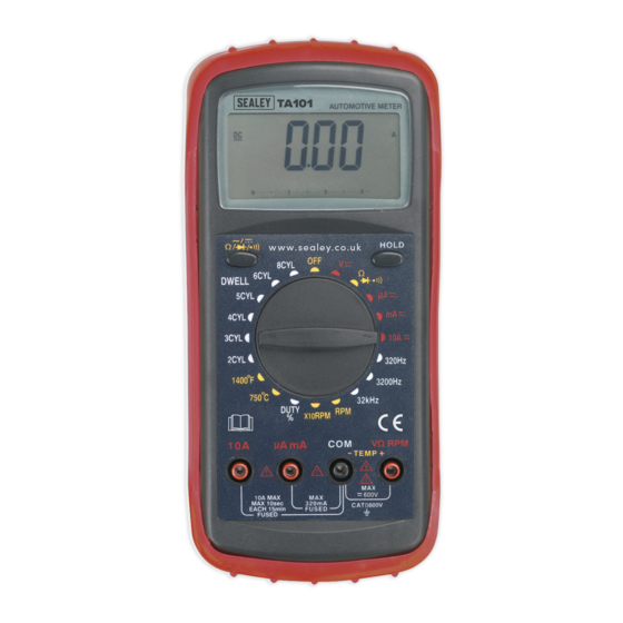
2. INTRODUCTION
Durable bi-composite case and integral stand suitable for the toughest
workshop conditions. Large, hi-contrast LCD display with 18mm high
digital read-out and analogue bar graph. Includes auto-ranging,
data-hold, auto-polarity, auto-power-off and low battery display
functions. Bar graph simplifies lambda sensor testing. Supplied with
capped test probes and K-type thermocouple.
Functions
Function
Test Range
A C
C u r r e n t
326µA
D C
C u r r e n t
326µA
AC Voltage
3.26V - 750V
326mV - 1000V
DC Voltage
typically
Diode test
<50 Ohms
Continuity test
Frequency
320Hz - 32kHz
2cyl 180°- 8cyl 45°
Dwell
Angle
t a c h o m e t e r
0 - 3260rpm and
0 - 3260rpm x10
r e s i s t a n c e
326Ω − 32.6MΩ
-20°C to 750°C
t e m p e r a t u r e
-4°F
0 - 99.9%
D u t y
C y c l e
Display:
3 3/4 digits LCD display with a max. reading 3260. Digital height 18mm.
Polarity:
Auto polarity indication.
measurement Rate:
3 times per second.
Over Range Indication:
"OL" displayed on the LCD.
Low Battery Indication:
the
Auto-Power- Off:
Analyser automatically shuts down after approx. 10 minutes of inactivity.
Press "Hold" to switch on again.
Operating Environment:
0°C to 40°C (32°F to 104°F) at <75% relative humidity.
Storage Environment:
-10°C to 50°C (14°F to 122°F) at <75% relative humidity.
Power:
Single standard 9 Volt battery (PP3).
Fuse:
F10A/250V and F0.5A/250V.
Dimensions:
200 x 93 x 50 mm.
Weight Approx:
Approx. 400g including battery and holder.
Function Guide (Fig.2)
1.
OFF Position
2.
AC/DC voltage (+10)
3.
Resistance/Diode/Audible Continuity (+10)
4.
AC/DC Current (+10)
5.
Frequency
C o n n e c t i o n s
-
10A
AmA / 10A + COm
µ
-
10A
1mA
v
RPm
+
Ω
v
RPm
+
COm
Ω
to
1400°F
v
RPm
+
Ω
symbol is displayed when the battery voltage drops below the operating level.
6.
Tachometer
7.
Duty Cycle
8.
Temperature
9.
Dwell Angle
10.
Select AC/DC/Resistance/Diode/Continuity
Original Language Version
INStruCtIONS FOr:
12 FUNCTION DIGITAL AUTOmOTIvE ANALYSER
MODEL No:
COm
COm
TA101
Fig.2
tA101 Issue No.2 - 19/12/11
Fig.1
Advertisement

Related Manuals for Sealey TA101


Summary of Contents for Sealey TA101
- Page 1 TA101 MODEL No: thank you for purchasing a Sealey product. Manufactured to a high standard this product will, if used according to these instructions and properly maintained, give you years of trouble free performance. IMPORTANT: PLEASE READ THESE INSTRUCTIONS CAREFULLY. NOTE THE SAFE OPERATIONAL REQUIREmENTS, WARNINGS & CAUTIONS. USE THE PRODUCT CORRECTLY AND WITH CARE FOR THE PURPOSE FOR WHICH IT IS INTENDED.
- Page 2 Connect the test leads in series with the circuit under test and read the current on the display. 4.3.4. For DC current, the polarity of the red test lead will be displayed as well as the value. tA101 Issue No.2 - 19/12/11 Original Language Version...
- Page 3 5.3. Do not store the analyser in a place of high humidity or high temperature 6. PARTS LIST Item Description Parts tA101.01 tESt LEADS tA101.02 9V BAttErY tA201.01 tHErMOCOuPLE ‘K’ tYPE tA101 Issue No.2 - 19/12/11 Original Language Version...
-
Page 4: Environmental Protection
ONLY dispose of or recycle according to local authority regulations. under the Waste Batteries and Accumulators regulations 2009, Jack Sealey Ltd are required to inform potential purchasers of products containing batteries (as defined within these regulations), that they are registered with Valpak’s registered compliance scheme.