
Related Manuals for Krone AM 203 CV


Summary of Contents for Krone AM 203 CV
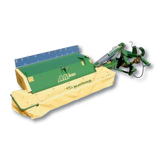
- Page 1 Operating Instructions No. 227-4 GB Disc Mower AM 203 CV AM 243 CV / + B (from machine no. 403 700) AM 283 CV / + B...
- Page 2 Krone-Disc Mower Models: AM 203 CV; AM 243 CV; AM 243 CV + B; AM 283 CV; AM 283 CV + B to which this declaration relates corresponds to the relevant basic safety and health...
-
Page 3: I. Foreword
Read these operating instructions carefully before you Maschinenfabrik Bernard Krone GmbH Heinrich-Krone-Straße 10, D 48480 Spelle use the machine, and pay special attention to the safety instructions. Jahr Masch. - Page 4 List of Contents Foreword ..........................1 List of Contents ........................2 III. General ..........................3 Introduction Position of Information Labels with safety-relevant contents on the Machine .......6 Position of General Information Labels on the Machine ............8 Technical Data for Disc Mower .....................9 Preparing for Operation Attaching the Disc Mower to the Tractor ................10 P.T.O.
-
Page 5: Iii. General
III. General 1. Operation in Accordance with 5. The operator´s clothing should be tight fitting. Avoid wearing loose fitting clothes. Specifications 6. Keep the machine clean to prevent the danger of fire! The disc mower is designed solely for normal agricultural use (operation in accordance with specifications). - Page 6 22.Persons are not allowed to enter the working area! 5.When using P.T.O. shafts with overload or free wheel clutches that are not covered by the guards on the 23.Keep clear of the area of rotation and swing of the tractor, the overload or free wheel clutches must be equipment! fixed on the implement side! 24.Hydraulic controls must only be operated if no persons...
- Page 7 Danger of infection! technical requirements defined by the manufacturer! 8. Before carrying out any work on the hydraulic The best guarantee is to use only original KRONE parts! systems, lower the machine to the ground, depressurize the system and turn off the engine! 10.Where gases are stored, only refill with nitrogen.
- Page 8 1. Introduction The KRONE Disc mower is equipped with all necessary safety features (protective equipment). Not all danger points on this machine can be completely safeguarded with regard to the function of the machine. On the machine you will find appropriate warnings that point out this residual danger.
- Page 9 Move guards into position. The PTO shaft speed must not exceed 540 rpm! The operating pressure in the hydraulics system must not exceed 200 bar. Order No. 939 100-4 (1x) Order No. 939 572-0 (1x) 939 572-0 Do not touch any moving Never put your hand into parts of the machine.
- Page 10 139 888-0 139 889-0 939 428-2 939 180-2 (1x) 939 567-1 (1x) 939 428-1 (1x) 939 511-1 (1x) AM 203 CV 939 515-1 (1x) AM 203 CV 942 132-0 (1x) 939 512-2 (1x) AM 243 CV 939 518-2 (1x) AM 243 CV...
-
Page 11: Technical Data For Disc Mower
1.3 Technical Data for Disc Mower AM 203 CV / AM 243 CV / AM 283 CV AM 243 CV AM 283 CV Type AM 203 CV (AM 243 + B) (AM 283 CV + B) Cutting width [mm] 2000... -
Page 12: Attaching The Disc Mower To The Tractor
2. Preparing for Operation 2.1 Attaching the Disc Mower to the Tractor 1. The mower is designed solely for nor 5. The protective cloth covers must be regularly mal agricultural use. (Operation in checked. Covers that are worn or damaged must accordance with specifications) be replaced. - Page 13 The lower link arms (3) are connected to the coupling points provided, and the top link arm (2) is connected to the newly designed top link arm coupling point (1). Use hydraulic control device with floating position! AM-0-010 - Release the pressure before disconnecting hoses - When the hydraulic hoses are and before any work is carried out on the connected to the tractor, the hydraulic...
-
Page 14: P.t.o. Shaft
2.2 P.T.O. Shaft This mower is driven with a maximum 540 rpm power take-off shaft speed of Under no circumstances may it be operated with a higher power take-off shaft speed. The PTO shaft must only be fitted or removed when the power take-off shaft and the engine are turned off and the ignition key has been removed! The PTO shaft is slid onto the gearbox input shaft with... -
Page 15: Jack Stand
The rotation speed of the tine rotor can be adjusted by means of the change lever (1) after the retaining pin (2) on the conditioner gearbox (3) has been removed. KRONE 0139-441 AM-0-007 By turning the screw (1) with the spanner supplied, the gear shift process with the gear change lever (3) is made easier. -
Page 16: The Angle Of The Mower To The Tractor
The PTO shaft for the conditioner drive is mounted with the friction clutch (1) towards the gearbox and the free- running end (2) towards the conditioner. Attach the retaining chain (3) to the mower. The retaining chain should be inserted to prevent the PTO shaft guard from rotating with the shaft. -
Page 17: Transport Position
2.7 Transport Position To do this, the locking mechanism (2) is pulled from the tractor with the synthetic cord (1) and the mower brought to the transport position by activating the lifting cylinder. AM-1-058 The disc mower is folded upwards for transport. - After the drive is turned off, the mowing discs may continue to rotate. - Page 18 Always remember to attach the lights (1) to the lights bracket (2) on the disc mower when driving on public highways. Use standard attachable lights. AM-1-075 2.8 Detaching the Disc Mower from the tractor The ground underneath must be level and should be solid.
- Page 19 When coupling the disc mower to the tractor, it is essential that the compensation spring (2) be pushed back onto the retaining bolt (1) and secured with a hinge clip (3) and washer. Mounting the compensating spring is only possible in transport position. AM-0-013 2.9 Safety measures before mower operation •...
-
Page 20: Adjusting The Top Link Arm Coupling Point
(1) as necessary. Greater spring tension increases the actuation moment. Type Dimension x AM-1-063 AM 203 CV 81mm AM 243 CV 80 mm AM 283 CV 79 mm AM 283 CV + B... -
Page 21: Adjusting Piece For Lifting Cylinder And Flotation Spring
The lower bearing bolt for the lifting cylinder and the AM 243 CV flotation spring must be locked in the correct position on AM 203 CV the different mower types. This adjustment is performed at the factory and must not be changed. -
Page 22: Adjusting The Swath Width
3.6 Adjusting the Swath Width The swath width is adjusted by means of swath deflector plates (1) located under the swath hood on the mower. These can be adjusted by loosening the ring nuts (2) in the slot area. Fasten the ring nuts securely again after making the adjustment. -
Page 23: Changing Blades On The Cutting Discs With Blade Screw Connectors
3.8 Changing Blades on the Cutting Discs with Blade Screw Connectors Safe and reliable operation of the mower is only guaranteed with correctly fitted cutter blades. Missing and damaged cutting blades cause dangerous irregularities in the rotation. Cutting blades and fixing bolts must therefore be checked daily. -
Page 24: Adjusting The Conditioner Speed
– leaf crop = low conditioner speed First, the retaining pin (2) is removed. Then, the shift KRONE lever (1) is moved out or in to select the tine rotor speed. When the lever is pulled out (position “A”), the conditioner speed is 600 rpm. - Page 25 3.11 Adjusting the Position of the Conditioner Rotor to the Cutterbar The conditioner rotor (1) of the rotor with the V-shaped tines (2) can be adjusted to four different positions. This is done by adjusting the distance of the conditioner from the cutterbar.
- Page 26 Position of conditioner roller on cutter beam I: basic position II: position for longer crops III: position for very long crops IV: conditioner out of service I I I The conditioner may not be operated in position IV. Detach the propeller shaft completely from the machine.
-
Page 27: General
4. Maintenance 4.1 General Repair, maintenance and cleaning work must be carried out only when the drive and the engine are turned off! Danger, cutting discs continue to rotate! Remove ignition key. Take measures to ensure that the tractor can not be inadvertently started or roll away. -
Page 28: Oil Level Check And Oil Change For Cutterbar
4.2 Oil Level Check and Oil Change for Cutterbar When checking the oil in the cutterbar, always ensure that the cutterbar is secured by the transport safety device. High risk of injury! Oil Level Check To check the oil level in the cutterbar, first move it to transport position and secure with the transport safety device. - Page 29 To check the oil level for the gearbox, twist out the screw (1). The oil must come up to the oil check hole. Top up with oil if necessary. KRONE 0139-441 AM-0-032 Oil Change The oil should be changed after about 350 hectares of operation.
-
Page 30: Unlocking The Overload Coupling On The Drive Shaft To The Cutterbar And On The Conditioner Drive (Walterscheid)
4.6 Unlocking the Overload Coupling on the Drive Shaft to the Cutterbar and on the Conditioner Drive (Walterscheid) The overload coupling on the cutterbar drive can only be unlocked with the disc mower in the transport position. The cutterbar must be secured with the transport bracket. -
Page 31: Lubrication
Storage Before the next idle period (after the campaign or before a prolonged period of disuse) the hex. socket head cap screws have to be tightened firmly again. AMS-1-047 4.9 Lubrication PTO Shafts Lubricate the PTO shafts for the main drive and the conditioner drive at the points indicated and the time intervals indicated. - Page 32 Lubrication Plan for Disc Mowers 10 h 10 h 10 h 50 h 50 h 10 h AM-1-077 Lubricate at the lubrication points listed below after the specified number of operating hours. Refer to the section entitled “Technical Data” for the recommended types of oil and lubricant...
-
Page 33: Conditioner And Protective Cloth Covers
They must therefore be put in protective position before work commences. Safety first! Take no risks. Do not experiment with imitation parts. Use only original KRONE parts! AM-1-076... -
Page 34: Wide Swath Hood
6. Wide swath hood Basic setting The disc mower AM 243 CV + B an AM 283 CV + B are fitted with a wide swath hood. Once conditioned by the V-shaped steel tines of the conditioner rotor, the cut forage crop is evenly spread over the entire surface which considerably speeds up the drying process. - Page 35 Change-over to swathlaying mode If required the grass can also be laid in a swath. For this secure the deflector plates (1) in the marked holes and fold in the swath deflectors (2). AM 243 CV + B AM-4-013 AM 283 CV + B AM-97-02...
-
Page 36: Winter Storage
• Make a list of all replacement parts required, and order them in good time. It is easier for your KRONE dealer to obtain and fit the required parts out of the main season. This ensures that your machine is fully operational for the coming season. - Page 37 • Whenever you change cutter blades also check retaining components and replace them if necessary. TAKE NO RISKS! Use only original KRONE parts! Changing blades on cutter discs with quick-release blades Push the special tool (1) {blade key} between the cutter disc (4) and leaf spring (3) and press down with one hand.
- Page 38 Appendix The cutter blades can be turned around and used on both sides. When cutter blades are missing or damaged, they must be replaced as a complete set. This KRONE KRONE prevents dangerous unbalanced rotation. 139-889 139-888 If the thickness of the material between the hole and the end of the cutter blade has reduced to less than a = 7 mm, you must replace the cutter blade.
- Page 39 Appendix...
- Page 41 Supplement to Operating Instructions AM 203 CV / AM 243 CV / AM 243 CV + B / AM 283 CV / AM 283 CV + B 1. Assembly Instructions The following instructions give a detailed description of the assembly procedure for the above mentioned KRONE disc mowers.
- Page 42 – 3 – 6 – 9 AM-4-000...
- Page 43 M 10 x 16 – M 8 x 110 901 425 M 8 x 60 904 882 M 12 x 25 AM 203 CV 904 751 M 10 x 20 AM 243 CV AM 283 CV 904 732 M 8 x 25...
- Page 44 AM-4-005 AM-3-006 AM-2-004 AM-3-008 AM-3-007...
- Page 45 AM-4-102 AM-4-009 AM-4-010 AM-2-011 AM-2-013 AM-2-012 AM-4-101...
- Page 46 AM-4-015 53 72 AM-3-016 AM-3-017 AM-2-018 AM-2-019...
- Page 47 AM-2-021 AM-2-020 AM-2-023 AM-2-022 AM-4-024...
- Page 48 AM-4-026 AM-2-027 80 mm 60 mm AM-2-028...
- Page 49 AM-2-029 AM-4-030...
- Page 50 R O NE AM-2-031 AM-2-032 AM-2-033 AM-2-035 AM-2-034...
- Page 51 AM-2-036...
- Page 52 2. Montage Getriebe für 1000er Zapfwelle 1000 /min AM-4-037 250mm 250mm AM-2-038 AM-4-039...
- Page 53 AM-2-041 AM-2-040...
- Page 56 SELBSTFAHRENDER HOCH- LEISTUNGS-MÄH-AUFBEREITER SELF-PROPELLED MOWER CONDITIONER GROßPACKENPRESSEN FAUCHEUSE AUTOMOTRICE BIG BALERS PRESSES À GRANDES BALLES CUBIQUES DREISEITEN-KIPPER THREE-WAY TIPPING TRAILER REMORQUES BASCULANTES TRIBENNES Maschinenfabrik Bernard Krone GmbH, Heinrich-Krone-Straße 10, D-48480 Spelle (Germany), Tel.: 05977/935-0, Fax: 05977/935-339 Internet: http://www.krone.de; e-mail: bkrone-ldm@t-online.de...
Need help?
Do you have a question about the AM 203 CV and is the answer not in the manual?
Questions and answers