
Summary of Contents for DencoHappel F800
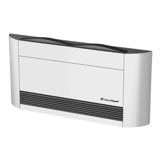
- Page 1 OPERATION MANUAL Dehumidifier Units F800 Using Know How for Heating and Duhumidification...
-
Page 2: Table Of Contents
2.1 Unit overview F800 ................. 7 2.2 F800 unit types: ................7 2.3 Accessories and Special Equipment ..........8 2.4 Functional principle of the F800 ........... 10 2.5 Air ventilation operation, no dehumidification requirement ... 11 2.6 Dehumidification Operation ............11 2.7 Technical Specifications ............... -
Page 3: Safety And User Instructions
F800 Safety and User Instructions Safety and User Instructions The F800 units are constructed using the state-of-the-art technology and according to recognized safety regulations. Use the unit when it is in a technically sound condition for the intended purpose observ-... -
Page 4: Identification Of Safety Instructions
Safety and User Instructions F800 Identification of safety instructions To designate the safety instructions the following symbols and notices are provided in appropriate places throughout this document: DANGER OF ELECTRICAL CURRENT! This symbol indicates a risk of electric shock when working on the equipment. -
Page 5: Safety-Conscious Work Procedures
– all protective devices are operating properly. Proper use The purpose of F800 units is to dehumidify, ventilate and heat air in indoor swim- ming pools and wet areas as well as to heat and filter water for pools. Proper use also includes observance of the operation manual and the inspection and maintenance conditions stipulated by DencoHappel. -
Page 6: Modifications And Changes
DencoHappel unit, its misapplication or modifications will invalidate the CE con- formity and void warranty. Spare parts Only original DencoHappel spare parts are allowed, since DencoHappel is not liable if third-party spare parts are used. Disposal Dispose of main and operating supply materials as well as other components and fil- ters according to their material type in a safe and environmentally-friendly manner, also refer to chapter "Disassembly and Disposal"... -
Page 7: Technical Description
Technical Description Technical Description Unit overview F800 The closed cooling cycle of a F800 consists of a scroll compressor, water-cooled con- denser (accessory), air-cooled condenser, expansion valve with injection-capillary tubes and air cooler. The cooling cycle is filled with environmentally-friendly R407C (see also Fig. -
Page 8: Accessories And Special Equipment
Technical Description F800 Accessories and special equipment Remote control F8ZRG – Humidity controller as remote control with operation and malfunction indicator, operating switch and setpoint setting – Operation with protective extra-low voltage from the basic unit – Control/regulation Additional switch box... - Page 9 F800 Technical Description Duct connector-piece F8ZST with flexible connection – For the supply air for rear wall mounting Unit rear wall painted F8ZHA – Painted in the color shade of the casing – Suitable for visible rear wall – e.g. for placement in front of a window...
-
Page 10: Functional Principle Of The F800
(RAL colors) Spare filter set F8ZEF Functional principle of the F800 The figure shows the refrigeration circuit with pool water condenser essentially consist- ing of: scroll compressor (1), air-cooled condenser (4) and pool water condenser (Option)(3), expansion valve (8) and evaporator or air- cooler (9). Refrigeration circuit filled with refrigerant. -
Page 11: Air Ventilation Operation, No Dehumidification Requirement
Air ventilation operation, no dehumidification requirement As long as no dehumidification requirement is needed with the humidity switch in the remote control, the F800 operates at low fan speed in ventilating/air circulation mode in order to largely avoid wet corners and clouding of the windows. -
Page 12: Technical Specifications
Technical Description F800 Technical specifications Technical data F800 Application range Private indoor pool Pool water surface up to 50 m Room air states (operating limits) min. approx. 22 °C / 40% rel. hum. (h = 35 kJ/kg) max. 36 °C / 60% rel. hum. (h = 94 kJ/... - Page 13 F800 Technical Description Technical data F800 3) Max. power consumption including external components from the accessories program 4) Recirculating air inlet temperature 30°C and fan speed 1/2 2.7.1 Unit dimensions with casing 1: installation opening 2: outside air connector (accessory)
-
Page 14: Shipping And Storage
3 Possible shipping damage must be reported no later than 4 days after delivery. It will not be possible to process claims if the above-mentioned points are not fulfilled. In both cases, consult the DencoHappel Sales Company installing the units. Transport NOTICE! Transport the unit only in its original packing. -
Page 15: Storage
Fig. 3-2 Storage NOTICE! – F800 may only be stored in weather-protected rooms – Observe the permissible storage conditions. – Remove the original packaging only just before installation. – If the unit is stored for a period of time before installation or commissioning, pro- tect it from damage through elements, build-up of dust and dirt! –... -
Page 16: Erect, Assemble And Connect
Positioning the unit The F800 can be installed to dehumidify indoor swimming pools or other damp areas, directly in the swimming pool hall or damp room or in ancillary rooms (rear-wall instal- lation). - Page 17 Only grip the unit on the base frame! The weight is considerably greater on the switch box side (refrigeration system with compressor)! Fig. 4-6 • Set the F800 only on a level and fortified surface. NOTICE! To reduce noise, set the unit without fail on a sound-absorbing surface.
- Page 18 Erect, assemble and connect F800 For this modification, proceed as follows: • Unscrew both plastic screws on the lower sheet as de- scribed in the Fig. 4-3 on page 16. • Push the lateral casing forwards and remove. Fig. 4-8 •...
- Page 19 Fig. 4-12 4.1.2 Two units in one plant Should two F800 be required for reaching the required dehumidification efficiency, these could be controlled and monitored in parallel by a common remote control. The additional switch box type F8ZRK should be installed outside of the protected zone 1 and 2 (3.50 m from the pool edge), preferably outside of the swimming pool.
- Page 20 Erect, assemble and connect F800 Prepare the unit as follows: • Open or cut the outside air connection. Be sure to hold the cut-out material tightly to avoid it fall- ing back into the interior of the unit! Otherwise the unit must be opened in order to remove the cut-out material.
- Page 21 F800 Erect, assemble and connect Fig. 4-16: Structure scheme 1: Air duct (building-side) 2: Flexible connection accessory: type F8ZST 3: Adapter with air connector accessory: type F8ZAD2 4: Air intake from the indoor swimming pool (e.g. on-site air hoses) diameter 180 mm 5: Outside-air connection (in front) accessory: type F8ZAA (diameter 150 mm) 4.1.5 Adapter for extract-air connection for setting up in ancillary rooms...
- Page 22 It is recommended to mount it on the opposite side of the unit under the ceiling. The outgoing-air fan is controlled from the F800. The unit switches the speed stages 1 and 2 of the outgoing-air fan appropriate to the operating state.
- Page 23 Erect, assemble and connect 4.1.7 Assemble back cover of the unit (optional) For installation of the F800 with examinable back panel, e.g. in front of windows, the unit rear wall can be mounted painted in the color shade of the casing (accessory).
-
Page 24: Connect Unit Water-Side
The setpoint temperature of the pool water should be main- Fig. 4-30 tained by these settings with the delivery of free thermal output to the pool water by the F800. PR-2013-0105-GB • Subject to modifications • R2-04/2016... - Page 25 Connection of pool water condenser 4.2.4 Connect pool water condenser (optional) The F800 can be equipped with a pool water condenser made of CuNi10Fe. This condenser should largely compensate the pool water's heat of vaporization loss, equivalent heat of evaporation = 0.674 kW/kg, by feedback of free thermal output in the dehumidification operation.
- Page 26 F800 1: Filtering equipment pump 2: Pool water condenser pump 3: Filter circuit counterflow heating 4: Pool water condenser in the F800 5: Non-return valve or flap F: Filter T: Pool water thermostat 4.2.5 Connect pool water pump (optional) Damage to the unit! Pressure and suction side must not be interchanged! The connecting lines must not be larger than 1/2".
-
Page 27: Electrical Installation
F800 Erect, assemble and connect Electrical installation The electrical connection may only be performed by a qualified licensed electrician. They must have proper professional training and experience in the relevant accident prevention regulations, as well as other generally recognized safety and occupa- tional health codes, perform unit jobs. - Page 28 Erect, assemble and connect F800 4.3.1 Electrical connection PR-2013-0105-GB • Subject to modifications • R2-04/2016...
- Page 29 F800 Erect, assemble and connect 4.3.2 Electrical connection – 2 units in one plant (only with accessory F8ZK) PR-2013-0105-GB • Subject to modifications • R2-04/2016...
-
Page 30: Assemble Remote Control (Optionally)
Open casing, mark screw connection holes, and mount with mounting materials suitable for the wall. • Avoid direct solar radiation, contact with cold walls or com- ponents as well as direct blowing by the F800. • Protect the remote control from splashing water! 108,3 Fig. -
Page 31: Commissioning And Operation
NOTICE! These instructions apply to initial commissioning and also for re-commissioning after an extended shut-down period. F800 unit may only be taken into operation by specialists or by DencoHappel service personnel! Requirements Check the following before switching on the unit and after all required installation pro- cedures have been completed: •... - Page 32 Commissioning and Operation F800 5.2.2 Adjust room temperature setpoint (only for units with additional heating register) To set the room temperature setpoint, proceed as follows: • Unscrew the plastic screw on the lower panel as described in the Fig. 4-3 on page 16.
-
Page 33: F800 Operation
F800 Commissioning and Operation 5.2.4 Economical operation The efficiency of the F800 depends largely on the selection of the pool water temper- ature, the hall air temperature, and the hall humidity. Generally the following ap- The higher the room temperature is above the pool water temperature and the higher plies: the inside air humidity is set, the more economical the dehumidification unit. -
Page 34: Maintenance, Cleaning And Troubleshooting
Cleaning 6.2.1 Clean enclosure • Clean the enclosure of the F800 with a soft cloth, possibly using a gentle cleaning agent. NOTICE! Do not clean the casing of the F800 with aggressive cleaning agents! 6.2.2 Clean/exchange air filter... - Page 35 F800 Maintenance, Cleaning and Troubleshooting • Take a hold of the filter, push slightly downwards, then fold tilt out of the slot/track from above and remove. • Clean the filter with flowing tap water or replace the filter (accessory). Fig. 6-1 •...
-
Page 36: Troubleshooting
Maintenance, Cleaning and Troubleshooting F800 Troubleshooting Occurring errors Possible reason Solution Authority • Unit cannot be No electricity Ensure availability of elec. current Users switched on • Cable incorrectly lain Check wiring and lay the cables Only authorized correctly specialists •... -
Page 37: Disassembly And Disposal
F800 Disassembly and Disposal Disassembly and Disposal ENVIRONMENTAL DAMAGE! Have qualified licensed staff dismantle and dispose of the unit! Dismantling To dismantle the unit proceed as follows: DANGER OF ELECTRICAL CURRENT! When carrying out decommissioning and dismantling work on the unit, disconnect all power supply connections, ensure the power cannot be inadvertently energized and verify that electric lines have been disconnected. -
Page 38: Eg Declaration Of Conformity
F800 dehumidifiers including accessories The F800 dehumidifiers, type designation F8SG, F8S, F8BG, F8B, F8PG, F8P, F8K, F8KG, are designed for dehumidification, ventilation, air heating, and pool water heating and filtering. Due to their easy installation and maintenance, the dehumidifiers may be used both in older and newly built premises, e.g. in swimming pool and whirlpool halls. - Page 39 F800 PR-2013-0105-GB • Subject to modifications • R2-04/2016...
- Page 40 DencoHappel is a global company with expertise in air treatment, air conditioning and air filtration. Our nearest sales and service teams will be glad to discuss ideas and develop creative and effective solutions with you. www.dencohappel.com...
Need help?
Do you have a question about the F800 and is the answer not in the manual?
Questions and answers