Table of Contents
Advertisement
Quick Links
Advertisement
Table of Contents

Related Manuals for Time Guard PDFM1500


Summary of Contents for Time Guard PDFM1500
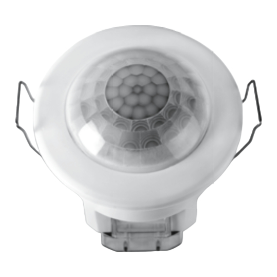
- Page 1 360º Flush Mount Ceiling PIR Light Controller Model: PDFM1500...
- Page 2 The light spread on all halogen The PDFM1500 utilises passive infrared technology to detect heat radiation of floodlights can be reduced by angling the floodlight moving human bodies. Upon detection, the attached lighting load will illuminate downwards on the mounting bracket.
- Page 3 ssive infrared technology to ing human bodies.Upon ng load will illuminate for od. An integral daylight ght-only operation. Time On ht Pollution and Dusk/Dawn Cable clamp Wiring cover yance over-lighting an area Levering area e neighbours. Light tly installing a unit or Cable clamp Wiring cover limited by carefully...
-
Page 4: Parts Included
2. Parts Included • PIR Sensor unit. • Instruction manual. Please keep safe for future reference. • Accessory Pack. Includes cable clamp wiring cover and 2 x screws. 3. Tools & Parts Needed • 3 core flexible cable. • Electric/hand-held drill & bits. • 65mm or 2.5 inch diameter hole cutter. • Terminal or Electricians screwdriver. • Small philips screwdriver. • Wire cutters. • Suitable mains interconnect cable. This product is suitable for indoor use only. 4. Selecting a Location The motion detector has a number of detection zones, at various vertical and horizontal angles as shown (see diagram A). -
Page 5: Installation
Reflective surfaces (ie pools of water or white-painted walls) and overhanging branches may cause false activation under extreme conditions. During extreme weather conditions the motion sensor may exhibit unusual behaviour. This does not indicate a fault with the sensor. Once normal weather conditions return, the sensor will resume normal operation. 5. Installation IMPORTANT Switch off the electricity at the fuse box by removing the relevant fuse or switching off the circuit breaker before proceeding with the installation. All fittings should be installed by competent person in accordance with IEE Wiring Regulations (BS7671) Do not attempt to install if you are suffering from nausea or dizzy spells or on medication with similar side effects. If in any doubt, consult a qualified electrician. - Page 6 6. Connection Connect the mains supply cable Live core (brown) to L and Neutral core (Blue) to N terminal. Connect the lighting cable Neutral core (blue) to N and Lighting Live core (brown) to the L1 terminal on the unit as follows (see diagram D):- LIVE (Brown) NEUTRAL (Blue) NEUTRAL (Blue) LIVE (Brown) L1 Load When wiring is complete, fit the cable clamp wiring cover to the sensor unit with the 2 screws provided. (diagram E) Set the two adjustment controls on the side of the unit (diagram C) to the following positions: TIME – Fully anti-clockwise (Test mode). DUSK – Fully clockwise. Push back the locating springs (diagram D) and feed the unit into the ceiling void via the 65mm hole. The locating springs will now fold back and hold the PDFM1500 in place.
- Page 7 7. Setting up Walk Test Procedure TIME – Fully anti-clockwise (Test Mode) DUSK – Fully clockwise The unit will now operate during daytime as well as at night, illuminating the lamp for approx. 5 seconds each time. This allows testing to be carried out to establish whether the sensor is covering the required area. The lamp will immediately illuminate as the unit goes through its “warm-up” period. After approximately 1 minute the lamp will extinguish. Try to remain outside the detection area during the warm-up period.
- Page 8 The DUSK control determines the level of darkness required for the unit to start operating. The setting is best achieved by the procedure below: Set the DUSK control knob fully anti-clockwise. The unit will now start operating at dusk. If you require the light to activate earlier, wait until the ambient light level reaches the level of darkness at which you wish the lamp to become operative, SLOWLY (a small step at a time) rotate the control in a clockwise direction until a point is reached where the lamp illuminates in response to a hand moving below the unit. Leave the control set at this point. At this position, the unit should become operative at approximately the same level of darkness each evening.
-
Page 9: Troubleshooting Guide
8. Troubleshooting Guide Problem Solution Cover PIR lens with a thick cloth. If the light • Lamp stays ON all the turns out, check detection area for heat or time at night. reflective source. If the light stays on, check wiring. See Connection. • PIR keeps Turn off at the isolation switch. Turn back on activating for again after 30 seconds. Leave for approximately no reason 15 minutes. (at random). If light activates, check area for false activation from heat, wind or reflective source. • PIR sensor will Check that the power is switched ON at the power not operate at all. supply or isolation switch. Turn OFF the power to the unit and check the wiring connections. -
Page 10: Technical Specifications
9. Technical Specifications Motion Detection Range: Up to 10 metres diameter (4.5m Radius) at mounting height of 3m Presence Detection Range: Up to 3 metres diameter (1.5m Radius) at mounting height of 3m 360º Detection Angle: Power Supply: 230 V AC ~ 50Hz Maximum Switchable Load: 1500W Halogen or Fluorescent/low energy lighting. Not suitable for discharge lighting. 250W fan load Time On Adjustment: 1 minute – 30 minutes Day & night or night only operation Dusk Level Adjustment: IP44 Environmental Protection:... -
Page 11: Year Guarantee
3 Year Guarantee In the unlikely event of this product becoming faulty due to defective material or manufacture within 3 years of the date of purchase, please return it to your supplier in the first year with proof of purchase and it will be replaced free first year with proof of purchase and it will be replaced free of charge. For years 2 and 3 or any difficulty in the first year telephone the helpline on 020 8450 0515. - Page 12 HELPLINE 020 8450 0515 or email helpline @ timeguard.com For a product brochure please contact: Timeguard Limited. Victory Park, 400 Edgware Road, London NW2 6ND Sales Offi ce: 020 8452 1112 or email csc @ timeguard.com Designed in the U.K. 67-058-425...
Need help?
Do you have a question about the PDFM1500 and is the answer not in the manual?
Questions and answers