Keithley 2000 User Manual
Hide thumbs
Also See for 2000:
- User manual (280 pages) ,
- Repair manual (109 pages) ,
- Calibration manual (88 pages)

Related Manuals for Keithley 2000


Summary of Contents for Keithley 2000
- Page 1 Model 2000 Multimeter User’s Manual 2000-900-01 Rev. J / August 2010...
- Page 2 Model 2000 Multimeter User’s Manual ©1994-2010, Keithley Instruments, Inc. All rights reserved. Cleveland, Ohio, U.S.A. Document Number: 2000-900-01 Rev. J / August 2010...
-
Page 4: Table Of Contents
Table of Contents General Information Feature overview..................1-2 Manual addenda ..................1-3 Safety symbols and terms ..............1-3 Specifications ..................1-3 Inspections ...................1-4 Options and accessories ..............1-5 Basic Measurements Introduction ..................2-2 Front panel summary ................2-3 Rear panel summary ................2-6 Power-up ....................2-8 Display ....................2-17 Measuring voltage ................2-18 Measuring current ................2-22 Measuring resistance .................2-24 Measuring frequency and period............2-26... - Page 5 STATus subsystem ................5-52 :SYSTem subsystem................5-61 :TRACe subsystem ................5-68 Trigger subsystem ................5-70 :UNIT subsystem ................5-74 Status and Error Messages Example Programs Program examples................C-2 Models 196/199 and 8840A/8842A Commands IEEE-488 Bus Overview Introduction ..................E-2 Bus description ..................E-4 Bus lines ....................E-6 Bus commands ..................E-8 Interface function codes..............E-15...
- Page 6 General Information...
-
Page 7: General Information
DC voltage accuracy and 0.008% 90-day basic resistance accuracy. At 6½ digits, the multimeter delivers 50 triggered readings/sec over the IEEE-488 bus. At 4½ digits, it can read up to 2000 readings/sec into its internal buffer. The Model 2000 has broad measure- ment ranges: μ... -
Page 8: Manual Addenda
Manual addenda Any improvements or changes concerning the instrument or manual will be explained in an addendum included with the manual. Be sure to note these changes and incorporate them into the manual. Safety symbols and terms The following symbols and terms may be found on the instrument or used in this manual. symbol on the instrument indicates that the user should refer to the operating instructions located in the manual. -
Page 9: Inspections
General Information Inspection The Model 2000 was carefully inspected electrically and mechanically before shipment. After unpacking all items from the shipping carton, check for any obvious signs of physical damage that may have occurred during transit. (Note: There may be a protective film over the display lens, which can be removed.) Report any damage to the shipping agent imme-... -
Page 10: Options And Accessories
Model 2001-TCSCAN: This is a thermocouple scanner card that installs in the option slot of the Model 2000. The card has nine analog input channels that can be used for high-ac- curacy, high-speed scanning. A built-in temperature reference allows multi-channel, cold- junction compensated temperature measurements using thermocouples. -
Page 11: Cables And Adapters
Model 2000 to instruments that use the standard BNC trigger connectors. Model 8504 DIN to BNC Trigger Cable: Allows you to connect Trigger Link lines one (Volt- meter Complete) and two (External Trigger) of the Model 2000 to instruments that use BNC trigger connectors. The Model 8504 is 1m long. -
Page 12: Basic Measurements
Basic Measurements... -
Page 13: Front Panel Summary
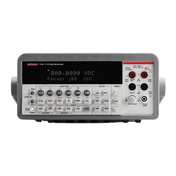
Basic Measurements This section summarizes front panel operation of the Model 2000. It is organized as fol- lows: • Front panel summary — Includes an illustration and summarizes keys, display, and connections. • Rear panel summary — Includes an illustration and summarizes connections. - Page 14 The front panel of the Model 2000 is shown in Figure 2-1. This figure includes important abbreviated information that should be reviewed before operating the instrument. Figure 2-1 SENSE Model 2000 front INPUT Ω 4 WIRE panel STEP SCAN CH10...
- Page 15 Shifted operation keys DELAY Sets user delay between trigger and measurement. HOLD Holds reading when the selected number of samples is within the selected tolerance. LIMITS Sets upper and lower limit values for readings. ON/OFF Enables/disables limits; selects beeper operation for limit testing. TEST Selects built-in tests, diagnostics, display test.
- Page 16 Input connections INPUT HI and LO Used for making DC volts, AC volts, 2-wire resistance measure- ments. AMPS Used in conjunction with INPUT LO to make DC current and AC current measurements. Also holds current input fuse (3A, 250V, fast blow, 5×20mm). SENSE Ω4 WIRE Used with INPUT HI and LO to make 4-wire resistance mea- sure-...
-
Page 17: Rear Panel Summary
Rear panel summary The rear panel of the Model 2000 is shown in Figure 2-2. This figure includes important abbreviated information that should be reviewed before operating the instrument. Figure 2-2 Model 2000 rear panel WARNING: WARNING: NO INTERNAL OPERATOR SERVICABLE PARTS,SERVICE BY QUALIFIED PERSONNEL ONLY. - Page 18 7007-1 and 7007-2. Power module Contains the AC line receptacle, power line fuse, and line voltage setting. The Model 2000 can be configured for line voltages of 100V/120V/220V/240VAC at line frequen- cies of 45Hz to 66Hz or 360Hz to 440Hz.
-
Page 19: Power-Up
Basic Measurements Power-up Line power connection Follow the procedure below to connect the Model 2000 to line power and turn on the instrument. Check to see that the line voltage selected on the rear panel (see Figure 2-3) is cor- rect for the operating voltage in your area. -
Page 20: Setting Line Voltage And Replacing Fuse
If the instrument repeatedly blows fuses, locate and correct the cause of the trouble before replacing the fuse. See the optional Model 2000 Repair Manual for troubleshooting information. If configuring the instrument for a different line voltage, remove the line voltage se- lector from the assembly and rotate it to the proper position. - Page 21 Basic Measurements Power-up sequence On power-up, the Model 2000 performs self-tests on its EPROM and RAM and momen- tarily lights all segments and annunciators. If a failure is detected, the instrument momen- tarily displays an error message and the ERR annunciator turns on. (Error messages are listed in Appendix B.)
-
Page 22: High Energy Circuit Safety Precautions
High energy circuit safety precautions To optimize safety when measuring voltage in high energy distribution circuits, read and use the directions in the following warning. WARNING Dangerous arcs of an explosive nature in a high energy circuit can cause severe personal injury or death. If the multimeter is connected to a high energy circuit when set to a current range, low resistance range, or any other low impedance range, the circuit is virtually shorted. - Page 23 Power-on defaults are the settings the instrument assumes when it is turned on. The Model 2000 offers two choices for the settings: factory and user. The power-on default will be the last configuration you saved. The SAVE and SETUP keys select the two choices of power-on defaults.
- Page 24 Table 2-2 Factory defaults Setting Factory default Autozero Buffer No effect Continuity Beeper Digits 4½ Fast (0.1 PLC) Rate 10Ω Threshold Current (AC and DC) 5½ Digits (AC) 6½ Digits (DC) Filter Count Moving average Mode Auto Range Relative Value Medium (DETector BANDwidth 30) Rate (AC) Medium (1 PLC)
- Page 25 Table 2-2 (cont.) Factory defaults Setting Factory default Resistance (2-wire and 4-wire) Digits 6½ Filter Count Mode Moving average Range Auto Relative Value Rate Medium (1 PLC) RS-232 Baud No effect Flow No effect Tx term No effect Scanning Channels 1-10 Mode Internal...
- Page 26 Table 2-2 (cont.) Factory defaults Setting Factory default Voltage (AC and DC) dB reference No effect dBm reference 75Ω Digits (AC) 5½ Digits (DC) 6½ Filter Count Mode Moving average Range Auto Relative Value Rate (AC) Medium* Rate (DC) Medium (1 PLC)
-
Page 27: Gpib Primary Address
See Section Four — Remote Operation for more GPIB information. Warm-up time The Model 2000 is ready for use as soon as the power-up sequence has completed. However, to achieve rated accuracy, allow the instrument to warm up for one hour. If the instrument has been subjected to extreme temperatures, allow additional time for internal temperatures to stabilize. -
Page 28: Display
Display The display of the Model 2000 is primarily used to display readings, along with the units and type of measurement. Annunciators are located on the top, bottom, right, and left of the reading or message display. The annunciators indicate various states of operation. See Fig- ure 2-1 for a complete listing of annunciators. -
Page 29: Measuring Voltage
Measuring voltage The Model 2000 can make DCV measurements from 0.1µV to 1000V and ACV measure- ments from 0.1µV to 750V RMS, 1000V peak. Connections Assuming factory default conditions, the basic procedure is as follows: Connect test leads to the INPUT HI and LO terminals. Either the front or rear inputs can be used;... -
Page 30: Low Level Considerations
Effects not noticeable when working with higher voltages are significant in micro- volt signals. The Model 2000 reads only the signal received at its input; therefore, it is im- portant that this signal be properly transmitted from the source. The following paragraphs indicate factors that affect accuracy, including stray signal pick-up and thermal offsets. - Page 31 To minimize the drift caused by thermal EMFs, use copper leads to connect the circuit to the Model 2000. A banana plug generates a few microvolts. A clean copper conductor such as #10 bus wire is ideal for this application. The leads to the input may be shielded or un- shielded, as necessary.
- Page 32 AC voltage offset The Model 2000, at 5½ digits resolution, will typically display 100 counts of offset on AC volts with the input shorted. This offset is caused by the offset of the TRMS converter. This offset will not affect reading accuracy and should not be zeroed out using the REL feature.
- Page 33 The Model 2000 can make DCI measurements from 10nA to 3A and ACI measurements from 1µAm to 3A RMS. NOTE See the previous discussion about crest factor in “Measuring voltage” in this sec- tion. Assuming factory default conditions, the basic procedure is as follows: Connect test leads to the AMPS and INPUT LO terminals.
-
Page 34: Amps Fuse Replacement
If the instrument repeatedly blows fuses, locate and correct the cause of the trouble before replacing the fuse. See the optional Model 2000 Repair Manual for troubleshooting information. Install the new fuse by reversing the procedure above. -
Page 35: Measuring Resistance
Measuring resistance The Model 2000 can make 2-wire and 4-wire resistance measurements from 100µΩ to 120MΩ. Connections Assuming factory default conditions, the basic procedure is as follows: Connect test leads to the Model 2000 as follows: For Ω2-wire, connect the test leads to INPUT HI and LO. - Page 36 Figure 2-6 Optional shield Shielded Two- and four- Model 2000 Cable wire resistance measurements STEP SCAN CH4 CH5 MATH TALK REAR LSTN SHIFT TIMER HOLD TRIG FAST SLOW FILT AUTO BUFFER STAT 2001 MULTIMETER Resistance Under Test Note: Source current flows from the INPUT HI to INPUT LO terminals.
-
Page 37: Measuring Frequency And Period
Trigger level Frequency and Period use a zero-crossing trigger, meaning that a count is taken when the frequency crosses the zero level. The Model 2000 uses a reciprocal counting technique to measure frequency and period. This method generates constant measurement resolution for any input frequency. - Page 38 Assuming factory default conditions, the basic procedure is as follows: Connect test leads to the INPUT HI and LO terminals of the Model 2000. Either the front or rear inputs can be used; place the INPUTS button in the appropriate position.
-
Page 39: Measuring Temperature
Thermocouples can be connected to the Model 2001-TCSCAN card, which plugs into the option slot of the Model 2000, or to an external thermocouple card, such as a Model 7057A, 7402, or 7014 installed in a Model 7001 or 7002 Switch System. - Page 40 JUNC — SIM, CH1 (simulated or referenced at Channel 1). Typically, a thermocou- ple card uses a single reference junction. The Model 2000 can simulate a reference junction temperature or use the reference junction on a switching card. Typical ref- erence junction temperatures are 0°C and 23°C.
-
Page 41: Math
NOTES Once enabled for a function, the mX+b and percentage calculations are in effect across function changes. The Model 2000 uses IEEE-754 floating point format for math calculations. MX + B This math operation lets you manipulate normal display readings (X) mathematically ac-... - Page 42 Press ENTER when done. The Model 2000 will display the result of the calculation. The result is positive when the input exceeds the reference and negative when the input is less than the reference. Engi- neering units are used to show values in the range 1 nano to 1000G.
- Page 43 1mW reference. With a user-programmable reference impedance, the Model 2000 reads 0dBm when the voltage needed to dissipate 1mW through the reference impedance is applied. The relationship between dBm, a refer- ence impedance, and the voltage is defined by the following equation: §...
- Page 44 Expressing DC or AC voltage in dB makes it possible to compress a large range of mea- surements into a much smaller scope. The relationship between dB and voltage is defined by the following equation: dB= 20 log ----------------- - where: V is the DC or AC input signal.
- Page 45 The Model 2000 uses the 1kΩ range to measure circuit continuity. After selecting conti- nuity, the unit prompts you for a threshold resistance level (1Ω-1000Ω). The Model 2000 alerts you with a beep when a reading is below the set level.
-
Page 46: Testing Diodes
The diode test measures voltages on the 3V range for the 1mA test current and the 10V range for the 100µA and 10µA ranges. If a reading is more than 10V, the Model 2000 dis- plays the “OVERFLOW” status message. -
Page 48: Measurement Options
Measurement Options... -
Page 49: Measurement Configuration
Measurement Options This section describes the front panel features of the Model 2000. For those measure- ment options accessible only by a remote interface, refer to Sections 4 and 5. This section is organized as follows: • Measurement configuration — Describes ranging, filtering, relative readings, digits of resolution, and measurement rate. - Page 50 Measurement Options The following paragraphs discuss configuring the multimeter for making measurements. See the end of Appendix A for information about optimizing readings for speed or accuracy. The selected measurement range affects both the ultimate digits and accuracy of the measurements as well as the maximum signal that can be measured.
- Page 51 FILTER lets you set the filter response to stabilize noisy measurements. The Model 2000 uses a digital filter, which is based on reading conversions. The displayed, stored, or trans- mitted reading is simply an average of a number of reading conversions (from 1 to 100).
- Page 52 Digits The display resolution of a Model 2000 reading depends on the DIGITS setting. It has no effect on the remote reading format. The number of displayed digits does not affect accuracy or speed. Those parameters are controlled by the RATE setting.
- Page 53 Rate The RATE operation sets the integration time of the A/D converter, the period of time the input signal is measured (also known as aperture). The integration time affects the usable digits, the amount of reading noise, as well as the ultimate reading rate of the instrument. The integration time is specified in parameters based on a number of power line cycles (NPLC), where 1 PLC for 60Hz is 16.67msec and 1 PLC for 50Hz and 400Hz is 20msec.
- Page 54 Bandwidth The rate setting for AC voltage and current measurements determines the bandwidth set- ting: • Slow — 3Hz to 300kHz. • Medium — 30Hz to 300kHz. • Fast — 300Hz to 300kHz. Bandwidth is used to specify the lowest frequency of interest. When the Slow bandwidth (3Hz to 300kHz) is chosen, the signal goes through an analog RMS converter.
-
Page 55: Trigger Operations
• A bus trigger (GET or *TRG) is received. • The front panel TRIG key is pressed. (The Model 2000 must be taken out of re- mote before it will respond to the TRIG key. Use the LOCAL key or send LOCAL... - Page 56 A programmable delay is available after event detection. It can be set manually or an auto delay can be used. With auto delay, the Model 2000 selects a delay based on the function and range. The AUTO settings are listed in Table 3-2.
- Page 57 Device actions The primary device action is a measurement. However, the device action block could in- clude the following additional actions: • Filtering — If the repeating filter is enabled, the instrument samples the specified number of reading conversions to yeildl single filtered reading. Only one reading con- version is performed if the filter is disabled, or after the specified number of reading conversions for a moving average filter is reached.
-
Page 58: External Triggering
TRIG key to trigger a single reading. Pressing the EXT TRIG key again toggles you back to continuous triggers. The Model 2000 uses two lines of the Trigger Link rear panel connector as External Trig- ger (EXT TRIG) input and Voltmeter Complete (VMC) output. The EXT TRIG line allows the Model 2000 to be triggered by other instruments. - Page 59 In a typical test system, you may want to close a channel and then measure the DUT con- nected to the channel with a multimeter. Such a test system is shown in Figure 3-6, which uses a Model 2000 to measure ten DUTs switched by a Model 7011 multiplexer card in a Model 7001/7002 Switch System.
- Page 60 Number of scans = 1 Channel spacing = TrigLink To run the test and store readings in the Model 2000 with the unit set for external triggers, press STEP or SCAN. The Model 2000 waits (with the asterisk annunciator lit) for an exter-...
- Page 61 Press STEP on the Model 7001/7002 to take it out of idle and start the scan. The scan- ner's output pulse triggers the Model 2000 to take a reading, store it, and send a trigger pulse. The following explanation on operation is referenced to the operation model shown in Figure 3-8.
- Page 62 The output Channel Ready pulse from the Model 7001/7002 triggers the multimeter to measure DUT #1 (point E). After the measurement is complete, the Model 2000 outputs a completion pulse (point F) and then loops back to point A, where it waits for another input trigger.
- Page 63 Figure 3-9 shows how a Keithley Model 706 Scanner can be connected to the Trigger Link of the Model 2000 using the adapter cable. With this adapter, a Model 706 could be substi- tuted for the Model 7001/7002 in the previous example. With the Model 706 set for External Triggering, the test would start when the single scan mode is selected and initiated.
-
Page 64: Buffer Operations
Buffer operations The Model 2000 has a buffer to store from two to 1024 readings and units. It also stores the channel number for scanned readings and overflow readings. In addition, recalled data includes statistical information, such as minimum, maximum, average, and standard devia- tion. -
Page 65: Recalling Readings
Recalling readings Use the following steps to view stored readings and buffer statistics: Press RECALL. The BUFFER annunciator indicates that stored readings are being displayed. The arrow annunciator indicates that more data can be viewed with the , and keys. As shown in Figure 3-10, use the cursor keys to navigate through the reading num- bers, reading values, and statistics. -
Page 66: Buffer Statistics
¦ – -- - ¨ ¨ ¸ ¸ © © ¹ ¹ ------------------------------------------------------------- - where: x i is a stored reading n is the number of stored readings NOTE The Model 2000 uses IEEE-754 floating point format for math calculations. -
Page 67: Limit Operations
Limit operations Limit operations set and control the values that determine the HI / IN / LO status of sub- sequent measurements. Limits can be applied to all measurement functions except continu- ity. The limit test is performed after mX+b and percent math operations. Unit prefixes are applied before the limit test, for example: •... -
Page 68: Enabling Limits
Enabling limits Use the following procedure to turn on the limits operation: Press the SHIFT-ON/OFF keys to view the present beeper status: BEEP: NEVER Use the keys to change the beeper status (NEVER, OUTSIDE, INSIDE). Press ENTER when done. When the multimeter returns to the normal display, the HI/IN/LO status is displayed along with the reading. -
Page 69: Scan Operations
Scanning overview A scanner lets you switch among a number of input signals to the Model 2000 for mea- surement. The channel control and scanning capabilities depend on whether an internal or external card is being used, as well as on the capabilities of the scanner card. Refer to the documentation supplied with the scanner card for specific connection information. -
Page 70: Front Panel Scanner Controls
Close a specific channel (or channel pair for 4-wire resistance). • Immediately open any internal closed channel (or channel pair for 4-wire resistance). With a scanner card installed in the option slot of the Model 2000, the following prompt is displayed when the CLOSE key is pressed: CLOSE CHAN:01... -
Page 71: Stepping And Scanning Trigger Model Additions
Stepping and scanning trigger model additions The trigger model presented in “Trigger operations” earlier in this section has some addi- tional capabilities when stepping or scanning. These are outlined below: • Timer — With this control source, event detection is immediately satisfied on the ini- tial pass. - Page 72 Figure 3-13 Idle Front panel trig- gering with scan- ning More Reading Readings Count (Trigger counter) Event Control Detection Source Output Trigger Immediate External Timer More Scan List Channels Length (Sample counter) Delay Device Action...
- Page 73 The next selection is for timed scans. (This is the Timer control source in the trigger model.) It sets a user-specified interval for starting scans. If you choose timed scans, the Model 2000 prompts for a time interval: 00H:00M:00.000S Use the...
- Page 74 Figure 3-14 shows how different settings of RDG CNT affect these operations: SHIFT-CONFIG Figure 3-14 Internal scan- TYPE: INT MIN CHAN: 1 Note: "Factory setup" on the ning example Model 2000 is assumed. MAX CHAN: 10 with reading TIMER? OFF count option 0010 0002 RDG CNT:...
- Page 75 Table 3-3 Bus commands parameters for stepping and scanning counters Operation :SAMPle:COUNt :TRIGger:COUNt STEP reading count SCAN scan list length (reading count) / (scan list length) Another configuration option for stepping and scanning is the timing of channel closures. The example of Figure 3-15 shows how different settings of TIMER and DELAY affect these operations.
- Page 76 Figure 3-15 SHIFT-CONFIG Internal scan- TYPE:INT ning example Note: "Factory setup" on the MIN CHAN: 1 Model 2000 is assumed. with timer and MAX CHAN: 10 delay options TIMER? RDG CNT: 0010 TIMER? ON 00H:00M:05.000S DELAY: MAN 00H:00M:05.000S RDG CNT: 0010...
- Page 77 Model 2000 only recognizes channel 1 when a step or scan is performed. If using a Model 7001 or 7002 to close channel 1 manually, the Model 2000 will not interpret that channel as the reference junction without a step or scan operation.
- Page 78 Figure 3-16 Model 7001 Model 2000 External scan- (from "reset setup") (from "factory setup") ning example with Model 7001 SCAN CHANNELS 1!1-1!10 CONFIGURE SCAN CHAN-CONTROL CHANNEL-SPACING TRIGLINK ASYNCHRONOUS CHAN-COUNT SCAN-CONTROL SCAN-COUNT SHIFT-CONFIG TYPE:EXT MIN CHAN: 001 MAX CHAN: 010 TIMER? OFF...
-
Page 79: System Operations
Section 4 — Remote Operation. Self-test The TEST selections are used as diagnostic tools to isolate problems within the Model 2000. Information on using these test procedures is included in the optional Model 2000 Re- pair Manual. Calibration The CAL selections are used to view the calibration date and next due date, to perform calibration, and to view the number of times calibration has been performed. - Page 80 Remote Operation...
-
Page 81: Remote Operation
• Programming syntax • Common commands Selecting an interface The Model 2000 multimeter supports two built-in remote interfaces: • GPIB bus • RS-232 interface You can use only one interface at a time. The factory interface selection is the GPIB bus. - Page 82 For more information about the RS-232 interface, see section RS-232 operation. The GPIB bus is the IEEE-488 interface. You must select a unique address for the Model 2000 multimeter. The address is displayed when the multimeter is turned on. At the factory, the address is set to 16.
- Page 83 8842 (Fluke Model 8840A/8842A). Confirm your selection by pressing ENTER. The multimeter returns to the measure- ment mode. Standard Commands for Programmable Instruments (SCPI) is fully supported by the GPIB and RS-232 interfaces. Always calibrate the Model 2000 multimeter using the SCPI language.
- Page 84 Keithley Models 196/199 Digital Multimeter The Model 2000 multimeter implements virtually all commands available in the Keithley Models 196/199 digital multimeter, except for the self-test and calibration commands. The commands are listed in Appendix D. See the Models 196/199 Digital Multimeter user manuals for more information about re- mote programming.
-
Page 85: Rs-232 Operation
You can break data transmissions by sending a ^C or ^X character string to the multime- ter. This clears any pending operation and discards any pending output. Selecting baud rate The baud rate is the rate at which the Model 2000 multimeter and the programming ter- minal communicate. Choose one these available rates: •... - Page 86 Model 2000 issues the X_ON, which it will do once its input buffer has dropped below half-full. The Model 2000 rec- ognizes X_ON and X_OFF sent from the controller. An X_OFF will cause the Model 2000 to stop outputting characters until it sees an X_ON.
- Page 87 The RS-232 serial port can be connected to the serial port of a controller (i.e., personal computer) using a straight through RS-232 cable terminated with DB-9 connectors. Do not use a null modem cable. The serial port uses the transmit (TXD), receive (RXD) and signal ground (GND) lines of the RS-232 standard.
-
Page 88: Gpib Bus Operation And Reference
GPIB bus standards The GPIB bus is the IEEE-488 instrumentation data bus with hardware and programming standards originally adopted by the IEEE (Institute of Electrical and Electronic Engineers) in 1975. The Model 2000 multimeter conforms to these standards: • IEEE-488-1987.1 •... -
Page 89: Gpib Bus Connections
GPIB bus connections To connect the Model 2000 multimeter to the GPIB bus, use a cable equipped with stan- dard IEEE-488 connectors as shown in Figure 4-2. Figure 4-2 IEEE-488 con- nector To allow many parallel connections to one instrument, stack the connector. Two screws are located on each connector to ensure that connections remain secure. - Page 90 To connect the Model 2000 multimeter to the IEEE-488 bus, follow these steps: Line up the cable connector with the connector located on the rear panel. The con- nector is designed so that it will fit only one way. Figure 4-4 shows the location of the IEEE-488 connector.
-
Page 91: Selecting The Primary Address
Selecting the primary address The Model 2000 multimeter ships from the factory with a GPIB address of 16. When the multimeter powers up, it momentarily displays the primary address. You can set the address to a value of 0-30. Do not assign the same address to another device or to a controller that are on the same GPIB bus. - Page 92 If the program message includes a query command, then the ENTER command is required to get the response message from the Model 2000 multimeter. The ENTER com- mand addresses the Model 2000 multimeter to talk. The following example program frag- ment demonstrates how OUTPUT and ENTER commands are used.
- Page 93 Serial Polls the Model 2000. REN (remote enable) The remote enable command is sent to the Model 2000 by the controller to set up the in- strument for remote operation. Generally, the instrument should be placed in the remote mode before you attempt to program it over the bus. Simply setting REN true does not ac- tually place the instrument in the remote state.
- Page 94 Use the GTL command to put a remote-mode instrument into local mode. The GTL com- mand also restores front panel key operation. Program fragment PRINT #1, "remote 16" 'Place 2000 in remote SLEEP 3 'Wait 3 seconds PRINT #1, "local 16" 'Place 2000 in local mode...
- Page 95 DCL command is not an addressed command, so all instruments equipped to im- plement DCL will do so simultaneously. When the Model 2000 multimeter receives a DCL command, it clears the Input Buffer and Output Queue, cancels deferred commands, and clears any command that prevents the processing of any other device command.
- Page 96 SPE, SPD (serial polling) Use the serial polling sequence to obtain the Model 2000 serial poll byte. The serial poll byte contains important information about internal functions, (see “status structure”). Gener- ally, the serial polling sequence is used by the controller to determine which of several in- struments has requested service with the SRQ line.
-
Page 97: Front Panel Gpib Operation
IFC (Interface Clear) command. • LSTN — This indicator is on when the Model 2000 Multimeter is in the listener active state, which is activated by addressing the instrument to listen with the correct MLA (My Listen Address) command. LSTN is off when the unit is in the listener idle state. -
Page 98: Status Structure
Status structure See Figure 4-5 for the Model 2000 Multimeters status structure. Instrument events, such as errors, are monitored and manipulated by four status register sets. Notice that these sta- tus register sets feed directly into the Status Byte Register. More detailed illustrations of these register sets are provided by Figures 4-5 through 4-9. -
Page 99: Condition Registers
Condition registers As Figure 4-5 shows, all status register sets have a condition register. A condition register is a real-time, read-only register that constantly updates to reflect the current operating con- ditions of the instrument. For example, while a measurement is being performed, bit B4 (Meas) of the Operation Condition Register is set. -
Page 100: Enable Registers
Enable registers As Figure 4-5 shows, each status register set has an enable register. An enable register is programmed by you and serves as a mask for the corresponding event register. An event bit is masked when the corresponding bit in the enable register is cleared (0). When masked, a set bit in an event register cannot set a bit in the Status Byte Register (1 AND 0 = 0). - Page 101 Enable Register (B15 - B11) (B10) (B9) (B8) (B7) (B6) (B5) (B4) (B3) (B2) (B1) (B0) (See Figure 4-10). Idle = Idle state of the 2000 & = Logical AND Trig = Triggering OR = Logical OR Meas = Measuring...
- Page 102 Figure 4-8 BHF BAV Measurement Measurement (B15 - B12) (B11) (B10) (B9) (B8) (B7) (B6) (B5) (B4) (B3) (B2) Condition Register (B1) (B0) event status Measurement Event (B15 - B12) (B11) (B10) (B9) (B8) (B7) (B6) (B5) (B4) (B3) (B2) (B1) (B0) Register &...
- Page 103 Output Queue is considered cleared when it is empty. An empty Output Queue clears the MAV bit in the Status Byte Register. Read a message from the Output Queue by addressing the Model 2000 multimeter to talk after the appropriate query is sent.
- Page 104 Status Byte and Service Request (SRQ) Service request is controlled by two 8-bit registers: the Status Byte Register and the Ser- vice Request Enable Register. Figure 4-10 shows the structure of these registers. Figure 4-10 Status Summary Messages Status byte and service request Read by Serial Poll (SRQ)
- Page 105 Status Byte Register The summary messages from the status registers and queues are used to set or clear the appropriate bits (B0, B2, B3, B4, B5, and B7) of the Status Byte Register. These bits do not latch, and their states (0 or 1) are solely dependent on the summary messages (0 or 1). For example, if the Standard Event Status Register is read, its register will clear.
- Page 106 Service request enable register This register is programmed by you and serves as a mask for the Status Summary Mes- sage bits (B0, B2, B3, B4, B5, and B7) of the Status Byte Register. When masked, a set sum- mary bit in the Status Byte Register cannot set bit B6 (MSS/RQS) of the Status Byte Register.
- Page 107 Typically, service requests (SRQs) are managed by the serial poll sequence of the Model 2000. If an SRQ does not occur, bit B6 (RQS) of the Status Byte Register will remain cleared and the program will simply proceed normally after the serial poll is performed. If an SRQ does occur, bit B6 of the Status Byte Register will set and the program can branch to a ser- vice subroutine when the SRQ is detected by the serial poll.
-
Page 108: Trigger Model (Gpib Operation)
Trigger model (GPIB operation) This section describes how the Model 2000 Multimeter operates over the GPIB bus. The flowchart in Figure 4-11 summarizes operation over the bus and is called the trigger model. It is called the trigger model because operation is controlled by SCPI commands from the Trigger subsystem (see Section 5 for more information). -
Page 109: Trigger Model Operation
IMMediate — Event detection is immediately satisfied allowing operation to continue. • MANual — Event detection is satisfied by pressing the TRIG key. The Model 2000 Multimeter must be in LOCAL mode for it to respond to the TRIG key. Press the LO- CAL key or send LOCAL 16 over the bus to remove the instrument from the remote mode. - Page 110 to yield a single filtered reading. If the moving filter is active, or filter is disabled, then only one reading conversion is performed. Figure 4-12 From Delay block of To Output Trigger block of Trigger Model (See Figure 4-11) Trigger Model (See Figure 4-11). Device action (trigger model) Figure 4-12...
-
Page 111: Programming Syntax
Programming syntax The information in this section covers syntax for both common commands and SCPI com- mands. For information not covered here, see the IEEE- 488.2 and SCPI standards. Command words Program messages are made up of one or more command words. Commands and command parameters Common commands and SCPI commands may or may not use a parameter. -
Page 112: Query Commands
• Parameter types: The following are some of the more common parameter types: <b> Boolean: Used to enable or disable an instrument operation. 0 or OFF dis- ables the operation, and 1 or ON enables the operation. Example: :CURRent:AC:RANGe:AUTO ON Enable auto ranging <name>... -
Page 113: Case Sensitivity
Most command that require a numeric parameter(<n>) can also use the DEFault, MINi- mum, and MAXimum parameters for the query form. These query forms are used to deter- mine the *RST default value and the upper and lower limits for the fundamental command. Examples: :TRIGger:TIMer? DEFault... - Page 114 Short-form rules Use the following rules to determine the short-form version of any SCPI command: • If the length of the command word is four letters or less, no short form version exists. Example: :auto = :auto • These rules apply to command words that exceed four letters: •...
-
Page 115: Program Messages
Program messages A program message is made up of one or more command words sent by the computer to the instrument. Each common command is simply a three letter acronym preceded by an asterisk (*). SCPI commands are categorized in the :STATus subsystem and are used to help explain how command words are structured to formulate program messages. - Page 116 Command path rules • Each new program message must begin with the root command, unless it is optional (e.g., [:SENSe]). If the root is optional, simply treat a command word on the next level as the root. • The colon (:) at the beginning of a program message is optional and need not be used.
-
Page 117: Response Messages
“Multiple Command Messages”), the multiple response messages for all the queries is sent to the computer when the Model 2000 is addressed to talk. The responses are sent in the order that the query commands were sent and are separated by semicolons (;). -
Page 118: Common Commands
Returns an ID code that indicates which memory option is installed and whether or not the optional scanner card is installed. *RCL <NRf> Recall command Returns the Model 2000 to the setup configu- ration stored in the specified memory loca- tion. *RST Reset command Returned the Model 2000 to the *RST default conditions. - Page 119 *CLS — Clear Status Clear status registers and error queue Description Use the *CLS command to clear (reset to 0) the bits of the following registers in the Model 2000: • Standard Event Register • Operation Even Register • Error Queue •...
- Page 120 parameter value that is sent with the *ESE command. For example, to set the CME and QYE bits of the Standard Event Enable Register, send the following command: *ESE 36 Where: CME (bit B5) = Decimal QYE (bit B2) = Decimal <NRf>...
- Page 121 Bit B6, User Request (URQ) — A set bit indicates that the LOCAL key on the Model 2000 front panel was pressed. • Bit B7, Power ON (PON) — A set bit indicates that the Model 2000 has been turned off and turned back on since the last time this register has been read.
- Page 122 Description The identification code includes the manufacturer, model number, serial number, and firmware revision levels, and is sent in the following format: KEITHLEY INSTRUMENTS INC., MODEL 2000, xxxxxxx, yyyyy/zzzzz Where: xxxxxxx is the serial number yyyyy/zzzzz is the firmware revision levels of the digital board ROM and dis-...
- Page 123 Description On power-up or when the *CLS or *RST is executed, the Model 2000 goes into the Op- eration Complete Command Idle State (OCIS). In this state, no pending overlapped com- mands exist. The Model 2000 has three overlapped commands: •...
- Page 124 'Wait two seconds GOSUB ReadRegister 'Read register to show that OPC is not set PRINT #1, "output 16; :abort" 'Place 2000 back in idle GOSUB ReadRegister 'Read register to show that OPC is now set ReadRegister: PRINT #1, "output 16; *esr?"...
- Page 125 When used with the :INITiate or :INITiate:CONTinuous ON command, an ASCII “1” will not be sent to the Output Queue and the MAV bit will not set until the Model 2000 goes back into the idle state. The initiate operations are not considered finished until the instrument goes into the idle state.
- Page 126 Parameters <NRf>=0 Description Use this command to return the Model 2000 to the configuration stored in memory. The *SAV command is used to store the setup configuration in memory location. Only one setup configuration can be saved and recalled. The Model 2000 ships from the factory with :SYSTen:PRESet defaults loaded into the available setup memory.
- Page 127 *RST — RESET Return 2000 to *RST defaults Description When the *RST command is sent, the Model 2000 performs the following operations: Returns the Model 2000 to the *RST default conditions (see SCPI tables). Cancels all pending commands. Cancels response to any previously received *OPC and *OPC? commands.
- Page 128 The Service Request Enable Register is shown in Figure 4-15. Notice that the decimal weight of each bit is included in the illustration. The sum of the decimal weights of the bits that you wish to set is the value that is sent with the *SRE command. For example, to set the ESB and MAV bits of the Service Request Enable Register, send the following com- mand: *SRE 48...
- Page 129 • Bit 4, Message Available (MAV)-A set bit indicates that a message is present in the Output Queue. The message is sent to the computer when the Model 2000 is ad- dressed to talk. • Bit 5, Event Summary Bit (ESB)-A set bit indicates that an enabled standard event has occurred.
- Page 130 Send bus trigger to 2000 Description Use the *TRG command to issue a GPIB trigger to the Model 2000. It has the same effect as a group execute trigger (GET). Use the *TRG command as an event to control operation. The Model 2000 reacts to this trigger if BUS is the programmed control source.
- Page 131 The :INITiate commands remove the Model 2000 from the idle state. The device opera- tions of :INITiate are not considered complete until the Model 2000 returns to idle. By send- ing the *WAI command after the :INITiate command, all subsequent commands will not execute until the Model 2000 goes back into idle.
- Page 132 SCPI Command Reference...
-
Page 133: Scpi Command Reference
SCPI Command Reference This section contains reference information on programming the Model 2000 with the SCPI commands. It is organized as follows: SCPI Signal Oriented Measurement Commands — Covers the signal oriented measure- ment commands. These commands are used to acquire readings. - Page 134 “one-shot” measurement mode. You then use the :READ? command to trigger a measurement and acquire a reading (see :READ?). When this command is sent, the Model 2000 will be configured as follows: • The function specified by this command is selected.
- Page 135 Description This query command requests the latest post- processed reading. After sending this command and addressing the Model 2000 to talk, the reading is sent to the computer. This command does not affect the instrument set- This command does not trigger a measurement. The command simply requests the last available reading.
- Page 136 READ? command :READ? Description Typically, this command is used with the instrument in the “one-shot” mea- surement mode to trigger and acquire a specified number of readings. The :SAMPle:COUNt command is used to specify the number of readings (see Trigger Subsystem). Note that the readings are stored in the buffer. When this command is sent, the following commands execute in the order that they are presented: :ABORt...
-
Page 137: Measure Command
MEASure command :MEASure[:<function>]? <function> = CURRent:AC AC current CURRent[:DC] DC current VOLTage:AC AC voltage VOLTage[:DC] DC voltage RESistance 2-wire resistance FRESistance 4-wire resistance PERiod Period FREQuency Frequency TEMPerature Temperature DIODe Diode testing CONTinuity Continuity test Description This command combines all of the other signal oriented measurement commands to perform a “one-shot”... -
Page 138: Scpi Command Subsystems Reference Tables
SCPI command subsystems reference tables Tables 5-2 through 5-11 summarize the commands for each SCPI sub- system. The following list includes the SCPI subsystem commands and the table number where each command is summarized. CALCulate command summary (Table 5-2) DISPlay command summary (Table 5-3) FORMat command summary (Table 5-4) ROUTe command summary (Table 5-5) SENSe command summary (Table 5-6) - Page 139 Table 5-2 CALCulate command summary Default Command Description SCPI parameter √ :CALCulate[1] Subsystem to control CALC 1: √ :FORMat <name> Select math format (NONE, MXB, PERCent). PERCent √ :FORMat? Query math format. √ :KMATh Path to configure math calculations: :MMFactor <NRf> Set “m”...
- Page 140 Table 5-3 DISPlay command summary Default Command Description SCPI parameter :DISPlay √ [:WINDow[1]] √ :TEXT Path to control user text messages. (Note 1) √ :DATA <a> Define ASCII message “a” (up to 12 characters). √ :DATA? Query text message. √ :STATe <b>...
- Page 141 Table 5-5 ROUTe command summary Default Command Description SCPI parameter ROUTe Commands to control scanner card: :CLOSe <chan num> Close specified channel (1 to 10) or channel pair (1 to 5). :STATe? Query closed channel (or channel pair). :OPEN:ALL Open all input channels (1 through 10). :MULTiple Path to close and open multiple channels: :CLOSe <list>...
- Page 142 Table 5-6(cont.) SENSe command summary Default Command Description SCPI parameter √ :CURRent:AC Path to configure AC current. √ :NPLCycles <n> Set integration rate (line cycles; 0.01 to 10). √ :NPLCycles? Query line cycle integration rate. √ :RANGe Path to configure measurement range: √...
- Page 143 Table 5-6(cont.) SENSe command summary Default Command Description SCPI parameter √ :VOLTage:AC Path to configure AC voltage. √ :NPLCycles <n> Set integration rate (line cycles; 0.01 to 10). √ :NPLCycles? Query line cycle integration rate. √ :RANGe Path to configure measurement range: √...
- Page 144 Table 5-6(cont.) SENSe command summary Default Command Description SCPI parameter √ :RESistance Path to configure resistance: √ :NPLCycles <n> Set integration rate (line cycles; 0.01 to 10). √ :NPLCycles? Query line cycle integration rate. √ :RANGe Path to configure measurement range: √...
- Page 145 Table 5-6(cont.) SENSe command summary Default Command Description SCPI parameter :TEMPerature Path to configure temperature: :NPLCycles <n> Set integration rate (line cycles; 0.01 to 10). :NPLCycles? Query line cycle integration rate. :REFerence <n> Specify reference; -200 to 1372 :STATe <b> Enable or disable reference.
- Page 146 Table 5-6(cont.) SENSe command summary Default Command Description SCPI parameter :PERiod Path to configure period. :THReshold Path to select the threshold voltage range: :VOLTage :RANGe <n> Select threshold range (0 to 1010). :RANGe? Query threshold range. :REFerence <n> Specify reference (0 to 1). :STATe <b>...
- Page 147 Table 5-7 STATus command summary Default Command Description SCPI parameter √ :STATus (Note 1) :MEASurement Path to control measurement event registers: [:EVENt]? Read the event register. (Note 2) :ENABle <NRf> Program the enable register. (Note 3) :ENABle? Read the enable register. √...
- Page 148 Enable or disable beeper. √ [:STATe]? Query state of beeper. √ :LOCal Take 2000 out of remote and restore operation of front panel controls (RS-232 only). :REMote Place 2000 in remote (RS-232 only). :RWLock Lockout front panel controls (RS-232 only).
- Page 149 Table 5-10 Trigger command summary Default Command Description SCPI parameter √ :INITiate Subsystem command path: √ [:IMMediate] Initiate one trigger cycle. √ :CONTinuous <b> Enable or disable continuous initiation. (Note 1) √ :CONTinuous? Query continuous initiation. √ :ABORt Reset trigger system. √...
- Page 150 Table 5-11 UNIT command summary Default Command Description SCPI parameter :UNIT √ Select temperature measurement units (C, F, or K). :TEMPerature <name> √ :TEMPerature? Query temperature units. Path to configure voltage units. :VOLTage Select ACV measurement units (V, DB or DBM). :AC <name>...
-
Page 151: Calculate Subsystem
Calculate subsystem The commands in this subsystem are used to configure and control the Calculate subsystems and are summarized in Table 5-2. :CALCulate[1] These commands are used to configure and control the MXB (polynomial) and percent math calculations. Detailed information on math calculations is provided in Section 2. - Page 152 Query :MUNits? Query units for mx+b Description This command is used to specify the units data element for the mx+b cal- culation. Use any three letters from ‘A’ through ‘Z’. :PERCent <NRf> :CALCulate [1]:KMATh:PERCent <NRf> Specify target value for percent calculation Parameter <Nrf>...
- Page 153 :FORMat <name> CALCulate2:FORMat <name> Specify CALC2 format Parameters <name> = NONE No calculations MEAN Mean value of readings in buffer SDEViation Standard deviation of readings in buffer MAXimum Largest reading in buffer MINimum Lowest reading in buffer Query :FORMat? Query programmed math format Description This command is used to specify the format for the CALC2 math calcula- tion.
- Page 154 CALC2 is enabled: PRINT #1, “output 02; :calc2:form max” ‘ Select format PRINT #1, “output 02; :calc2:imm?” ‘ Perform math and query result PRINT #1, “enter 02” ‘ Get response from 2000 :DATA? :CALCulate2:DATA? Read CALC2 result Description This query command is used to read the result of the CALC2 calculation.
- Page 155 :CALCulate3 These commands are used to configure and control the CALC3 limit test. [:DATA] <n> :CALCulate3:LIMit [1]:UPPer[:DATA] <n> Specify upper limit1 :CALCulate3:LIMit [1]:LOWEer[:DATA] <n> Specify lower limit Parameters <n> = -100e6 to 100e6Specify limit value DEFault Set specified upper limit to 1 Set specified lower limit to -1 MINimum Set specified limit to -100e6...
- Page 156 Note that sending the :IMMediate command does not initiate a reading conversion. Program PRINT #1, “output 16;:trig:sour bus” ‘ Place 2000 in one-shot mode SLEEP 3 ‘ Wait three seconds PRINT #1, “output 16;:calc:imm...
-
Page 157: Display Subsystem
All front panel controls (except LOCAL) are disabled. Normal display op- eration can be resumed by using the :ENABle command to enable the dis- play or by putting the Model 2000 into local mode (press LOCAL). :TEXT commands :DATA <a>... - Page 158 :STATe <b> :DISPlay[WINDow[1]]:TEXT:STATe <b> Control (on/off) message Parameters <b> = 0 or OFF Disable text message 1 or ON Enable text message Query :STATe? Query state of message mode. Description This command enables and disables the text message mode. When en- abled, a defined message is displayed.
-
Page 159: Format Subsystem
:FORMat subsystem The commands in this subsystem are used to select the data format for transferring instrument readings over the bus. The BORDer command and DATA command only affect readings transferred from the buffer. (i. e. SENSE:DATA? or CALC:DATA? are always sent in ASCII.) These commands are summarized in Table 5-4. - Page 160 SREAL will select the binary IEEE754 single precision data format. Fig- ure 5-2 shows the normal byte order format for each data element. For example, if three valid elements are specified, the data string for each reading conversion is made up of three 32-bit data blocks. Note that the data string for each reading conversion is preceded by a 2-byte header that is the binary equivalent of an ASCII # sign and 0.
-
Page 161: Border Command
:BORDer command :BORDer <name> :FORMat:BORDer <name> Specify binary byte order Parameters <name> = NORMal Normal byte order for binary formats SWAPped Reverse byte order for binary formats Query :BORDer? Query byte order Description This command is used to control the byte order for the IEEE754 binary formats. -
Page 162: Elements Command
:ELEMents command :ELEMents <item list> :FORMat:ELEMents <item list> Parameters <item list>: READing Includes reading in data string CHANnel Includes channel number UNITs Includes units NOTE: Each item in the list must be separated by a comma (,). Query :ELEMents? Query elements in data string Description This command is used to specify the elements to be included in the data string for each measurement conversion. -
Page 163: Route Subsystem
ROUTe subsystem The commands in this subsystem are used to configure and control switching and are summarized in Table 5-5. Single channel (or channel pair) control Like operation from the front panel, the following commands let you close a single channel (or channel pair for 4-pole operation) on an internal scan- ner card. -
Page 164: Multiple Channel Control
:CLOSe:STATe? :ROUTe:CLOSe:STATe? Query closed channel or channel pair Description The response message for this query command indicates the channel (or channel pair) that has been closed on the internal scanner card using the :rout:close <chan num> command (or channels closed from the front pan- el). - Page 165 the 4-pole mode is selected. Use the rout:multiple:open <list> command to open channel 11. Examples of a list: list = (@1,3,5) Channels 1, 3, and 5. = (@1:5) Channels 1 through 5. When this command is sent, the front panel channel number annunciators are disabled.
-
Page 166: Scan Commands
Query programmed scan list Description The Model 2000 can operate with an external switch system, such as the Keithley Model 7001 or 7002. The Model 2000 can measure up to 800 channels that are switched by the external switching system. This com- mand is used to define the external scan list. - Page 167 Query scan operation Description This command is used to select and perform the desired scan operation. When INTernal is selected, the Model 2000 scans the channels of the in- ternal switching card according to how the scan is configured (see :SCAN[:INTernal]).
-
Page 168: [Sense[1]] Subsystem
[SENSe[1]] subsystem The Sense 1 Subsystem is used to configure and control the measure- ment functions of the Model 2000. A function does not have to be select- ed before you program its various configurations. A function can be selected any time after it has been programmed. Whenever a pro- grammed function is selected, it assumes the programmed states. -
Page 169: Data Command
:DATA command :DATA? [:SENSe[1]]:DATA? Return reading. Description This query command is used to read the latest instrument reading. This command returns the “raw” reading or a reading that is the result of the Reference (REL from the front panel) operation. For example, if a refer- ence value of 1.0 is established, the reading returned by this command is the “raw”... -
Page 170: Hold Command
:HOLD Command The following commands are used to configure and control the Hold fea- ture. For details on Hold, refer to “Trigger Model, Device Action” in this section and “Hold” in Section 3. :WINDow <NRf> [:SENSe[1]]:HOLD:WINDow <NRf><name> Set Hold window Parameter <NRf>... -
Page 171: Speed Commands
Speed Commands :NPLCycles <n> [:SENSe[1]]:CURRent:AC:NPLCycles <n> Set NPLC for ACI [:SENSe[1]]:CURRen[:DC]:NPLCycles <n> Set NPLC for DCI [:SENSe[1]]:VOLTage:AC:NPLCycles <n> Set NPLC for ACV [:SENSe[1]]:VOLTage[:DC]:NPLCycles <n> Set NPLC for DCV Set NPLC for Ω2 [:SENSe[1]]:RESistance:NPLCycles <n> Set NPLC for Ω4 [:SENSe[1]]:FRESistance:NPLCycles <n> [:SENSe[1]]:TEMPerature:NPLCycles <n>... -
Page 172: Range Commands
This command is used to manually select the measurement range for the specifed measurement function. The range is selected by specifying the expected reading as an absolute value. The Model 2000 will then go to the most sensitive range that will accommodate that expected reading. - Page 173 :AUTO <b> [:SENSe[1]]:CURRent:AC:RANGe:AUTO <b> Control auto range for ACI [:SENSe[1]]:CURRent[:DC]:RANGe:AUTO <b> Control auto range for DCI [:SENSe[1]]:VOLTage:AC:RANGe:AUTO <b> Control auto range for ACV [:SENSe[1]]:VOLTage[:DC]:RANGe:AUTO <b> Control auto range for DCV Control auto range for Ω2 [:SENSe[1]]:RESistance:RANGe:AUTO <b> Control auto range for Ω4 [:SENSe[1]]:FRESistance:RANGe:AUTO <b>...
- Page 174 :REFerence <n> commands :REFerence <n> [:SENSe[1]]:CURRent:AC:REFerence <n> Specify reference for ACI [:SENSe[1]]:CURRent[:DC]:REFerence <n> Specify reference for DCI [:SENSe[1]]:VOLTage:AC:REFerence <n> Specify reference for ACV :SENSe[1]]:VOLTage[:DC]:REFerence <n> Specify reference for DCV Specify reference for Ω2 [:SENSe[1]]:RESistance:REFerence <n> Specify reference for Ω4 [:SENSe[1]]:FRESistance:REFerence <n> [:SENSe[1]]:FREQuency:REFerence <n>...
- Page 175 :STATe <b> [:SENSe[1]]:CURRent:AC:REFerence:STATe <b> Control reference for ACI [:SENSe[1]]:CURRent[:DC]:REFerence:STATe <b> Control reference for DCI [:SENSe[1]]:VOLTage:AC:REFerence:STATe <b> Control reference for ACV [:SENSe[1]]:VOLTage[:DC]:REFerence:STATe <b> Control reference for DCV Control reference for Ω2 [:SENSe[1]]:RESistance:REFerence:STATe <b> Control reference for Ω4 [:SENSe[1]]:FRESistance:REFerence:STATe <b> [:SENSe[1]]:FREQuency:REFerence:STATe <b> Control reference for FREQ [:SENSe[1]]:PERiod:REFerence:STATe <b>...
-
Page 176: Digits Command
:DIGits command :DIGits <n> [:SENSe[1]]:CURRent:AC:DIGits <n> Specify resolution for ACI [:SENSe[1]]:CURRent:DC:DIGits <n> Specify resolution for DCI [:SENSe[1]]:VOLTage:AC:DIGits <n> Specify resolution for ACV [:SENSe[1]]:VOLTage:DC:DIGits <n> Specify resolution for DCV Specify resolution for Ω2 [:SENSe[1]]:RESistance:DIGits <n> Specify resolution for Ω4 [:SENSe[1]]:FRESistance:DIGits <n> [:SENSe[1]]:PERiod:DIGits <n>... -
Page 177: Average Commands
:AVERage commands The :AVERage commands are used to configure and control the filter. The Filter is explained in Section 3. :STATe <b> [:SENSe[1]]:CURRent:AC:AVERage:STATe <b> Control filter for ACI [:SENSe[1]]:CURRent[:DC]:AVERage:STATe <b> Control filter for DCI [:SENSe[1]]:VOLTage:AC:AVERage:STATe <b> Control filter for ACV [:SENSe[1]]:VOLTage[:DC]:AVERage:STATe <b>... - Page 178 :COUNt <n> [:SENSe[1]]:CURRent:AC:AVERage:COUNt <n> Specify filter count for ACI [:SENSe[1]]:CURRent[:DC]:AVERage:COUNt <n> Specify filter for DCI [:SENSe[1]]:VOLTage:AC:AVERage:COUNt <n> Specify filter count for ACV [:SENSe[1]]:VOLTage[:DC]:AVERage:COUNt <n> Specify filter count for DCV Specify filter count for Ω2 [:SENSe[1]]:RESistance:AVERage:COUNt <n> Specify filter count for Ω4 [:SENSe[1]]:FRESistance:AVERage:COUNt <n>...
-
Page 179: Bandwidth Command
BANDwidth? Query selected bandwidth Description The Model 2000 uses three bandwidth settings for ACI and ACV mea- surements; 3 (3Hz-300kHz), 30 (30Hz-300kHz) and 300 (300Hz- 300kHz). To achieve best accuracy, you should use the bandwidth setting that best reflects the frequency of the input signal. For example, if the in- put signal is 40Hz, then a bandwidth setting of 30 should be used. -
Page 180: Thermocouple Commands
:TYPE? Query thermocouple type Description This command is used to configure the Model 2000 for the thermocouple type that you are using to make temperature measurements. These commands are used to configure the reference junction for thermo- couple temperature measurements. - Page 181 :SIMulated <n> [:SENSe[1]]:TEMPerature:TCouple:RJUNction[1]:SIMulated <n> Parameters <n> = 0 to 50 Specify temperature in °C 32 to 122 Specify temperature in °F 273 to 323 Specify temperture in K DEFault 23°C, 73.4°F, 296K MINimum 0°C, 32°F, 273K MAXimum 50°C, 122°F, 323K Query :SIMulated? Query simulated reference...
-
Page 182: Diode Command
:REAL:OFFSet <n> [:SENSe[1]]:TEMPerature:TCouple:RJUNction[1]:REAL:OFFSET <n> Parameters <n> = -0.09999 to 0.09999Specify voltage offset at 0°C DEFault 0.05463 MINimum -0.09999 MAXimum 0.09999 Query :OFFSet? Query voltage offset :OFFSet? DEFault Query *RST default voltage offset :OFFSet? MINimum Query lowest allowable voltage offset :OFFSet? MAXimum Query largest allowable voltage offset Description This command is used to specify the offset voltage at 0°C for the specified reference junction. -
Page 183: Status Subsystem
Description These query commands are used to read the event registers. After send- ing one of these commands and addressing the Model 2000 to talk, a dec- imal value is sent to the computer. The binary equivalent of this value determines which bits in the appropriate register are set. - Page 184 SCPI Command Reference 5-53 Measurement Event Register: Bit B0, Reading Overflow (ROF) — Set bit indicates that the reading ex- ceeds the measurement range of the instrument. Bit B1, Low Limit (LL) — Set bit indicates that the reading is less than the Low Limit 1 setting.
- Page 185 5-54 SCPI Command Reference Questionable Event Register: Bits B0 through B3 — Not used. Bit B4, Temperature Summary (Temp) — Set bit indicates that an invalid reference junction measurement has occurred for thermocouple temper- ature measurements. Bits B5, B6 and B7 — Not used. Bit B8, Calibration Summary (Cal) —...
- Page 186 Idle Trig Meas Decimal 1024 Weighting (2 ) (2 ) (2 ) Value Events : Idle = Idle state of the 2000 Value : 1 = Operation Event Set Trig = Triggering 0 = Operation Event Cleared Meas = Measuring...
-
Page 187: Enable Command
5-56 SCPI Command Reference :ENABle command :ENABle <Nrf> :STATus:MEASurement:ENABle <NRf> Program Measurement Event Enable Register :STATus:QUEStionable:ENABle <NRf> Program Questionable Event Enable Register :STATus:OPERation:ENABle <NRf> Program Operation Event Enable Register Parameters <NRf> = 0 Clear register <NRf> = 128 Set bit B7 Set bit B0 Set bit B8 Set bit B1... -
Page 188: Enable Register
Trig Meas 1024 Decimal Weighting (2 ) (2 ) (2 ) Value Value : 1 = Enable Operation Event Events : Idle = Idle state of the 2000 0 = Disable (Mask) Operation Event Trig = Triggering Meas = Measuring... -
Page 189: Preset Command
See [:EVENt] for register bit descriptions. After sending one of these commands and addressing the Model 2000 to talk, a decimal value is sent to the computer. The binary equivalent of this decimal value indicates which bits in the register are set. -
Page 190: Queue Commands
SCPI defined messages, and positive (+) numbers are used for Keithley defined messages. The messages are listed in Appen- dix B. After this command is sent and the Model 2000 is addressed to talk, the “oldest” message in the queue is sent to the computer. NOTE... - Page 191 5-60 SCPI Command Reference :ENABle <list> :STATus:QUEue:ENABle <list> Enable messages for Error Queue Parameter <list> = (numlist) where numlist is a specified list of messages that you wish to enable for the Error Queue. Query :ENABle? Query list of enabled messages Description On power-up, all error messages are enabled and will go into the Error Queue as they occur.
-
Page 192: System Subsystem
SCPI Command Reference 5-61 :SYSTem subsystem The SYSTem subsystem contains miscellaneous commands that are summarized in Table 5-8. :BEEPer command [:STATe] <b> :BEEPer[:STATe] <b> Enable or disable beeper Parameters <b> = 1 or ON Enable beeper 0 or OFF Disable beeper Query [:STATe]? Query state of beeper... - Page 193 :POSetup <name> command :POSetup <name> :SYSTem:POSetup <name> Program power-on defaults Parameters <name> = RST Select *RST defaults on power up PRESet Select :SYSTem:PRESet defaults on power up SAV0 Select saved defaults on power up Query :POSetup? Query power-on setup Description This command is used to select the power-on defaults.
- Page 194 The messages in the queue are preceded by a number. Negative (-) num- bers are used for SCPI defined messages, and positive (+) numbers are used for Keithley defined messages. Appendix B lists the messages. NOTE The :SYSTem:ERRor? query command performs the same function as the :STATus:QUEue? query command (see STATus subsystem).
-
Page 195: Azero Commands
Important Note: Before you can enable or disable auto-zero, the Model 2000 must first be in the idle state. The Model 2000 can be placed in the idle state by first disabling continuous initiation (:INITiate:CONTinuous OFF), and then sending the :ABORt command. After sending the :STATe command, readings can be re-started by sending :INITiate:CONTinuous ON or :INITiate. - Page 196 5-10 also illustrates the key-press codes. The queue for the :KEY? query command can only hold one key-press. When :KEY? is sent over the bus, and the Model 2000 is addressed to talk, the key-press code number for the last key pressed (either physically...
- Page 197 CH10 MATH TALK REAR LSTN SHIFT 350V 1100V TIMER HOLD TRIG FAST SLOW FILT AUTO BUFFER STAT PEAK PEAK 2000 MULTIMETER 500V MX+B CONT PERIOD TCOUPL PEAK INPUTS Ω2 Ω4 SHIFT FREQ TEMP RANGE DELAY HOLD LIMITS ON/OFF TEST LOCAL...
-
Page 198: Line Frequency Query
However, the user may wish to lock out front keys during RS-232 communications (see :RWLock). This action command isu sed to take the Model 2000 out of the remote state and enables the operation of front panel keys. Note that this com- mand can only be sent over the RS-232 interface. -
Page 199: Trace Subsystem
Description This command is used to read the status of storage memory. After send- ing this command and addressing the Model 2000 to talk, two values sep- arated by commas are sent to the computer. The first value indicates how many bytes of memory are available, and the second value indicates how many bytes are reserved to store readings. -
Page 200: Feed Command
Send buffer readings Description When this command is sent and the Model 2000 is addressed to talk, all the readings stored in the buffer are sent to the computer. The format that readings are sent over the bus is controlled by the :FORMat subsystem. -
Page 201: Trigger Subsystem
Take 2000 out of idle state Description This command takes the Model 2000 out of the idle state. After all pro- grammed operations are completed, the instrument returns to the idle state if continuous initiation is disabled; (see next command). -
Page 202: Trigger Commands
:TRIGger commands :COUNt <n> :TRIGger[:SEQuence[1]]:COUNt <n> Set measure count Parameters <n> = 1 to 9999 Specify count Sets count to infinite DEFault Sets count to 1 MINimum Sets count to 1 MAXimum Sets count to 9999 Query :COUNt? Queries programmed count :COUNt? DEFault Queries *RST default count :COUNt? MINimum... - Page 203 :DELay <n> :TRIGger[:SEQuence[1]]:DELay <n> Set trigger model delay Parameters <n> = 0 to 999999.999 Specify delay in seconds DEFault 0 second delay MINimum 0 second delay MAXimum 999999.999 second delay Query :DELay? Query the programmed delay :DELay? DEFault Query the *RST default delay :DELay? MINimum Query the lowest allowable delay :DELay? MAXimum...
- Page 204 :TIMer <n> :TRIGger:[SEQuence[1]]:TIMer <n> Set interval for measure layer timer Parameters <n> = 0.001 to 999999.999 Specify timer interval in seconds Query :TIMer? Query programmed timer interval Description These commands are used to set the interval for the timer. Note that the timer is in effect only if the timer is the selected control source.
-
Page 205: Unit Subsystem
:UNIT subsystem The UNIT subsystem is used to configure and control the measurement units for TEMP, ACV, and DCV, and is summarized in Table 5-11. :TEMPerature command :TEMPerature <name> :UNIT:TEMPerature <name> Specify TEMP units Parameters <name> = C or CEL °C temperature units F or FAR °F temperature units... - Page 206 :DB:REFerence <n> :UNIT:VOLTage:AC:DB:REFerence <n> Specify dBm reference Parameter <n> = le-7 to 1000 Specify reference in volts Query :REFerence? Description This command is used to specify the dB reference level. When DB units is selected (:VOLTage:AC: DB), ACV db measurements are made using the specified dB reference level.
- Page 207 Query :REFerence? Description This command is used to specify the dB reference level. When DB units is selected (:VOLTage[:DC]:DB), DCV dB measurements are made using the specified dB reference level. The reference level is specified in volts and is not range dependent. For example, a dB reference level of 1 is 1V on all DCV measurement ranges.
- Page 208 Error Messages...
- Page 209 Status and Error Messages Table B-1 Status and error messages Number Description Event -440 Query unterminated after indefinite response -430 Query deadlocked Query unterminated -420 -410 Query interrupted Input buffer overrun -363 -350 Queue overflow -330 Self-test failed -314 Save/recall memory lost -315 Configuration memory lost -285...
-
Page 210: Status And Error Messages
Status and Error Messages Table B-1 Status and error messages Number Description Event -148 Character data not allowed -144 Character data too long -141 Invalid character data -140 Character data error -128 Numeric data not allowed -124 Too many digits -123 Exponent too large -121... - Page 211 Status and Error Messages Table B-1 Status and error messages Number Description Event +308 Buffer available +309 Buffer half full +310 Buffer full +311 Buffer overflow Calibration messages: 10 vdc zero error +400 +401 100 vdc zero error +402 10 vdc full scale error +403 -10 vdc full scale error +404...
- Page 212 Status and Error Messages Table B-1 Status and error messages Number Description Event +459 10 vac zero error +460 10 vac full scale error +461 10 vac noise error +462 100 vac zero error +463 100 vac full scale error +464 750 vac zero error +465...
- Page 213 +958 DDC Conflict Error +959 DDC No Remote Error +960 DDC Mode IDDC Error +961 DDC Mode IDDCO Error Keithley 199 Serial Poll Byte Events: +962 DDC Ready +963 DDC Reading Done +964 DDC Buffer Half Full +965 DDC Buffer Full...
- Page 214 Example Programs...
-
Page 215: C Example Programs
Example Programs All examples presume QuickBASIC version 4.5 or higher and a CEC IEEE-488 interface card with CEC driver version 2.11 or higher, with the Model 2000 at address 16 on the IEEE- 488 bus. The Model 2000 has independent controls for each of its measurement functions. This means, for example, that autorange can be turned on for DC voltage while leaving it off for AC voltage. - Page 216 'Example program to demonstrate changing function and range, 'taking readings on various functions 'For QuickBASIC 4.5 and CEC PC488 interface card 'Edit the following line to where the QuickBASIC 'libraries are on your computer '$INCLUDE: 'c:\qb45\ieeeqb.bi' 'Initialize the CEC interface as address 21 CALL initialize(21, 0) 'Reset the SENSe1 subsystem settings, along with the trigger 'model, each READ? will cause one trigger...
- Page 217 Changing any of the settings in the TRIGger subsystem does not automatically arm the Model 2000 for triggers. The following program sets up the Model 2000 to take one reading each time it receives an external trigger pulse. 'Example program to demonstrate one-shot external triggering 'For QuickBASIC 4.5 and CEC PC488 interface card...
- Page 218 When your program must wait until the Model 2000 has completed an operation, it is more efficient to program the 2000 to assert the IEEE-488 SRQ line when it is finished, rather than repeatedly serial polling the instrument. An IEEE-488 controller will typically address the in- strument to talk, then unaddress it, each time it performs a serial poll.
- Page 219 TRACe:FEED:CONTrol NEXT The following example program sets up the Model 2000 to take 20 readings as fast as it can into the buffer, then reads the data back after the buffer has filled.
- Page 220 'TRACe subsystem is not affected by *RST CALL SEND(16, "trac:poin 20", status%) CALL SEND(16, "trac:feed sens1;feed:cont next", status%) 'Start everything CALL SEND(16, "init", status%) 'Initialize reading$ while the 2000 is busy taking readings reading$ = SPACE$(4000) WaitSRQ: IF (NOT(srq%)) THEN GOTO WaitSRQ CALL SPOLL(16, poll%, status%) IF (poll% AND 64)=0 THEN GOTO WaitSRQ CALL SEND(16, "stat:meas?", status%)
- Page 221 The Model 2000-SCAN is an optional 10-channel scanner card for the Model 2000 Mul- timeter. Only one channel can be closed at a time. If you close a channel while another is already closed, the first one opens with break-before-make operation.
- Page 222 'Example program to demonstrate taking readings on different 'scanner channels 'For QuickBASIC 4.5 and CEC PC488 interface card 'Edit the following line to where the QuickBASIC 'libraries are on your computer '$INCLUDE: 'c:\qb45\ieeeqb.bi' 'Initialize the CEC interface as address 21 CALL initialize(21, 0) 'Reset controls in INIT, ARM;LAY1, ARM:LAY2, and TRIG subsystems 'and put trigger model in IDLE state, set function to DCV...
- Page 223 15 seconds apart, and each of the three readings in each group taken as fast as possible. The Model 2000 stores the readings in the buffer, and asserts SRQ when the buffer is full. The program waits for the SRQ, then reads the readings from the buffer.
- Page 224 ' now the buffer is armed CALL SEND(16, "rout:scan (@1:3)", status%) CALL SEND(16, "rout:scan:lsel int", status%) 'Start everything CALL SEND(16, "init", status%) 'Initialize reading$ while the 2000 is busy taking readings reading$ = SPACE$(2500) WaitSRQ: IF (NOT(srq%)) THEN GOTO WaitSRQ CALL SPOLL(16, poll%, status%) IF (poll% AND 64)=0 THEN GOTO WaitSRQ CALL SEND(16, "stat:meas", status%)
- Page 225 This example program illustrates the use of the Keithley Model 2000 DMM interfaced to the RS-232 COM2 port. The Model 2000 is setup to take 100 readings at the fastest possible rate (2000 per second). The readings are taken, sent across the serial port, and displayed on the screen.
- Page 226 PRINT #1, “:INIT:CONT OFF;:ABORT” ‘ Init off PRINT #1, “:SENS:FUNC ‘VOLT:DC’” ‘ DCV PRINT #1, “:SYST:AZER:STAT OFF” ‘ Auto zero off PRINT #1, “:SENS:VOLT:DC:AVER:STAT OFF” ‘ Filter off PRINT #1, “:SENS:VOLT:DC:NPLC 0.01” ‘ NPLC = 0.01 PRINT #1, “:SENS:VOLT:DC:RANG 10” ‘...
-
Page 228: Models 196/199 And 8840A/8842A Commands
Models 196/199 and 8840A/8842A Commands... - Page 229 AC current dB), range, analog and digital filter, rate, calibration, factory defaults, and self-test do not map one-for-one. Also note that the Model 2000 does not have the speed characteristics of the Models 196/199. Other commands of the Model 2000 have been add- ed to the 196/199 command set, such as frequency, temperature, and scanning.
- Page 230 Models 196/199 and 8840A/8842A Commands Table D-1 (cont.) Models 196/199 device-dependent command summary Mode Command Description Trigger mode Continuous on Talk One-shot on Talk Continuous on GET One-shot on GET Continuous on X One-shot on X Continuous on External Trigger One-shot on External Trigger Reading mode Readings from A/D converter...
- Page 231 Models 196/199 and 8840A/8842A Commands Table D-1 (cont.) Models 196/199 device-dependent command summary Mode Command Description Status Send machine status word (199 format only) Send error conditions (only supports no scanner, IDDC, IDDCO) Send Translator word list (since Translator is not sup- ported, replies with one space character) Send buffer size Send current value of “V”...
- Page 232 Models 196/199 and 8840A/8842A Commands Table D-1 (cont.) Models 196/199 device-dependent command summary Mode Command Description Simulated reference junction (for temperature func- tion) Real reference junction (for temperature function) Set simulated reference junction temperature using “V” command; 0 to 50 (°C).
- Page 233 Commands such as range, calibration, factory de- faults, and self-test do not map one-for-one. Also note that the Model 2000 does not have the speed characteristics of the Models 8840A/8842A. Other commands of the Model 2000 have been added to the 8840A/8842A command set, such as frequency, temperature, and scanner channels.
- Page 234 Table D-2 (cont.) Models 8840A/8842A device-dependent command summary Mode Command Description Trigger mode Trigger Rear panel Auto mode trigger delay T0 (default) Internal Disabled — External Enabled External Disabled External Enabled External Disabled Note: Delay is enabled by entering EXT TRIG mode while in local.
- Page 235 Table D-2 (cont.) Models 8840A/8842A device-dependent command summary Mode Command Description GET (cont.) Get status of JKM commands (temp. units; TC type and junction) String = 1jkm Get closed channel number String = 10nn Where: nn = 00 (all open) 01 through 10 (closed channel) Get simulated reference junction temperature String = xx.xxx (in °C)
-
Page 236: Eieee-488 Bus Overview
IEEE-488 Bus Overview... - Page 237 IEEE-488 Bus Overview Basically, the IEEE-488 bus is simply a communication system between two or more elec- tronic devices. A device can be either an instrument or a computer. When a computer is used on the bus, it serves to supervise the communication exchange between all the devices and is known as the controller.
- Page 238 IEEE-488 Bus Overview Through the use of control lines, a handshake sequence takes place in the transfer pro- cess of information from a talker to a listener. This handshake sequence helps ensure the credibility of the information transfer. The basic handshake sequence between an active controller (talker) and a listener is as follows: The listener indicates that it is ready to listen.
- Page 239 The IEEE-488 standards also include another addressing mode called secondary ad- dressing. Secondary addresses lie in the range of $60-$7F. Note, however, that many de- vices, including the Model 2000, do not use secondary addressing. Once a device is addressed to talk or listen, the appropriate bus transactions take place.
- Page 240 IEEE-488 Bus Overview Figure E-1 TO OTHER DEVICES IEEE-488 bus configuration DEVICE 1 ABLE TO TALK, LISTEN AND CONTROL (COMPUTER) DATA BUS DEVICE 2 ABLE TO TALK AND LISTEN 7001 DATA BYTE TRANSFER CONTROL DEVICE 3 ONLY ABLE TO LISTEN (PRINTER) GENERAL INTERFACE...
-
Page 241: Bus Lines
IEEE-488 Bus Overview The signal lines on the IEEE-488 bus are grouped into three different categories: data lines, management lines and handshake lines. The data lines handle bus data and com- mands, while the management and handshake lines ensure that proper data transfer and operation takes place. - Page 242 IEEE-488 Bus Overview The bus handshake lines operate in an interlocked sequence. This method ensures reli- able data transmission regardless of the transfer rate. Generally, data transfer will occur at a rate determined by the slowest active device on the bus. One of the three handshake lines is controlled by the source (the talker sending informa- tion), while the remaining two lines are controlled by accepting devices (the listener or lis- teners receiving the information).
-
Page 243: Bus Commands
IEEE-488 Bus Overview The instrument may be given a number of special bus commands through the IEEE-488 interface. This section briefly describes the purpose of the bus commands which are grouped into the following three categories. Uniline Commands — Sent by setting the associated bus lines true. For example, to assert REN (Remote Enable), the REN line would be set low (true). - Page 244 IEEE-488 Bus Overview ATN, IFC and REN are asserted only by the controller. SRQ is asserted by an external device. EOI may be asserted either by the controller or other devices depending on the di- rection of data transfer. The following is a description of each command. Each command is sent by setting the corresponding bus line true.
- Page 245 ORing the address with $40. Talk commands are used to address devices to talk. SCG (Secondary Command Group) — Commands in this group provide additional ad- dressing capabilities. Many devices (including the Model 2000) do not use these commands. The two unaddress commands are used by the controller to remove any talkers or listeners from the bus.
- Page 246 IEEE-488 Bus Overview E-11 Common commands are commands that are common to all devices on the bus. These commands are designated and defined by the IEEE-488.2 standard. Generally, these commands are sent as one or more ASCII characters that tell the device to perform a common operation, such as reset.
- Page 247 Figure E-3 Command codes...
- Page 248 For the various multiline commands, a specific bus sequence must take place to properly send the command. In particular, the correct listen address must be sent to the instrument before it will respond to addressed commands. Table E-3 lists a typical bus sequence for sending the addressed multiline commands.
- Page 249 Command groups supported by the Model 2000 are listed in Table E-5. Common com- mands and SCPI commands are not included in this list. Table E-5 IEEE command groups HANDSHAKE COMMAND GROUP NDAC = NOT DATA ACCEPTED NRFD = NOT READY FOR DATA...
-
Page 250: Interface Function Codes
The interface function codes for the Model 2000 are listed in Table E-6. The codes define Model 2000 capabilities as follows: Table E-6... - Page 251 DT (Device Trigger Function) — DTI defines the ability of the Model 2002 to have read- ings triggered. C (Controller Function) — The instrument does not have controller capabilities (C0). TE (Extended Talker Function) — The instrument does not have extended talker capabil- ities (TE0).
-
Page 252: Fieee-488 And Scpi Conformance Information
IEEE-488 and SCPI Conformance Information... - Page 253 Table F-2 lists the cou- pled commands used by the Model 2000. The Model 2000 complies with SCPI version 1991.0. Tables 5-2 through 5-11 list the SCPI confirmed commands, and the non-SCPI commands implemented by the Model 2000.
- Page 254 IEEE-488 and SCPI Conformance Information Table F-1 (cont.) IEEE-488 documentation requirements Requirements Description or reference (15) Macro information Not applicable. (16) Response to *IDN (identification). See “Common Commands” in Sec- tion 4. (17) Storage area for *PUD and *PUD? Not applicable. (18) Resource description for *RDT and *RDT? Not applicable.
- Page 255 IEEE-488 and SCPI Conformance Information Table F-2 Coupled commands Command Also changes :TRAC:POIN :TRAC:FEED:CONT :TRAC:CLE :TRAC:FEED:CONT Sense Subsystem Com- mands: ...:RANG:AUTO ...:RANG:UPP ...:REF presently displayed reading ...:REF:ACQ :ROUT:CLOS :ROUT:SCAN:LSEL NONE :ROUT:OPEN:ALL :ROUT:SCAN:LSEL NONE :ROUT:SCAN:INT :ROUT:SCAN:LSEL ... = Valid function command words (i.e. :VOLT:DC, :VOLT:AC, etc.)
- Page 256 M E A S U R E C O N F I D E N C E Keithley Instruments, Inc. Corporate Headquarters • 28775 Aurora Road • Cleveland, Ohio 44139 • 440-248-0400 • Fax: 440-248-6168 • 1-888-KEITHLEY • www.keithley.com 12/06...
Need help?
Do you have a question about the 2000 and is the answer not in the manual?
Questions and answers