Huawei BTS3900A Quick Installation
Hide thumbs
Also See for BTS3900A:
- Installation manual (168 pages) ,
- Installation manual / instruction manual (29 pages) ,
- Commissioning manual (20 pages)

Related Manuals for Huawei BTS3900A


Summary of Contents for Huawei BTS3900A
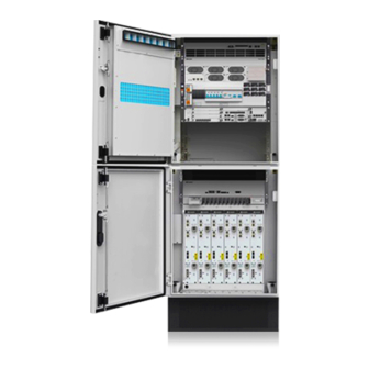
- Page 1 BTS3900A (Ver.C) Quick Installation Guide Issue: 01 Date: 2011-04-30 HUAWEI TECHNOLOGIES CO., LTD.
- Page 2 (-48 V DC power supply) DCDU-11A SLPU SLPU Fan box DCDU-11C DCDU-11C Junction Junction Junction box Ground- R R R R R ing bar g ba Ground- Ground- ing bar Grounding bar ing bar Copyright © Huawei Technologies Co., Ltd. 2011. All rights reserved.
-
Page 3: Installing The Base
Overview of the Cabinets IBBS200D IBBS200T Power Power Power Power distribution box distribution box CMUE Power box of the heating film CMUE Grounding bar Grounding bar Installing the Base Install two installation The installation blocks are placed in the auxiliary blocks on the base material package of the RFC. - Page 4 The PGND cable and signal cable cannot be bound or entangled. A certain distance Principles for grounding must be reserved between them to prevent the BTS3900A: the BTS3900A: interference from each other interference from each other. The upper cabinets are connected to the lower cabinets with equipotential cables.
-
Page 5: Installing The Cables
Installing the Cables In this section, the color of the cables and the equipment appe earance are for reference only. If the signal cable between the cabinets is redundant coil and If the signal cable between the cabinets is redundant, coil and d tie the extra length of the cable in the base d tie the extra length of the cable in the base. - Page 6 1 Connecting the Power Cables AC Power Supply Scenario 1. Connect the input power cable for the APM M30H Remove the AC protecting cap, open the AC input pow wer box. Connect the APM30H AC input power cable. Recover the AC protecting cap, close the AC input pow wer box.
- Page 7 1 Connecting the Power Cables AC Power Supply Scenario 3. Connect the power cable between the APM M30H and IBBS200D or IBBS200T (APM:IBBS=1:2) (APM:IBBS=1:2) This chapter is applicable to the scenario where the number of configured APM30Hs is half that of configured IBBS200Ds or IBBS200Ts.
- Page 8 1 Connecting the Power Cables AC Power Supply Scenario 3. Connect the power cable between the APM M30H and IBBS200D or IBBS200T (APM:IBBS=1:2) (APM:IBBS=1:2) Power cables for the heating films in the IBBS200Ds Prevent the wires from exposing out of the power box of the heating film of the heating film.
- Page 9 1 Connecting the Power Cables AC Power Supply Scenario 4. Connect the power cable between the APM M30H and IBBS200D or IBBS200T (APM:IBBS=1:1) (APM:IBBS=1:1) This chapter is applicable to the scenario where the number of configured APM30Hs equals that of configured IBBS200Ds or IBBS200Ts IBBS200Ts.
- Page 10 1 Connecting the Power Cables AC Power Supply Scenario 4. Connect the power cable between the APM M30H and IBBS200D or IBBS200T (APM:IBBS=1:1) (APM:IBBS=1:1) Power cables for the heating films in the IBBS200Ds Prevent the wires from exposing out of the power box of the heating film.
-
Page 11: Connecting The Transmission Cables
2 Connecting the Transmission Cables Principles for routing the transmission cables The transmission cables cannot cross the power cabl e, PGND cable, or RF cable when routed. Otherwise, the spacing between them must be greater than 30 m Extra length of transmission cables must be reserved d when they are curved. - Page 12 3 Installing the Monitoring Signal Cable -48 V DC Power Supply Scenarios 1. Scheme 1: TMC11H + 2 RFC 2. Scheme 2: 2 TMC11H + 2 RFC AC Power Supply Scenarios 1. Scheme 1:APM30H + RFC + TMC11H + IB BBS200D (IBBS200T) The installation procedure for connecting the monitoring...
- Page 13 3 Installing the Monitoring Signal Cable AC Power Supply Scenarios 2. Scheme 2:2 APM30H + 2 RFC + 2 IBBS20 00D (IBBS200T) UEIU 3. Scheme 3:APM30H + RFC + TMC11H +2 IB BBS200D (IBBS200T)
- Page 14 3 Installing the Monitoring Signal Cable AC Power Supply Scenarios 4. Scheme 4:2 APM30H + 2 RFC + TMC11H + + 4 IBBS200D (IBBS200T) 4 Connect the RFU Cables 1. (Optional) Connect inter-RFU RF signal ca ble. 2. Add the DIN connectors to the RF jumpers.
- Page 15 Sealing Treatment Recover the cable holes with protecting caps or covers which are removed from the equipments before. 1 Description of the Seal Modules i ti f th S l M d l TMC1 The seal modules for the cable holes in the IBBS S200D or the IBBS200T are the same as that in the TMC11H.
-
Page 16: Installing The Batteries
3 Sealing the Base 1. Close the cable holes on 2. Seal the cable holes with 3. Install the front panel both sides and at the rear of fireproof cl on the front of the base. the base. Fireproof Fireproof Baffle plate corrugated Baffle plate clay... - Page 17 Start -43.2 V DC to -57 V DC The normal status of the The normal status of the indicators on the CMUE: Power on the BTS3900A Clear the fault RUN indicator: Blinking ALM indicator: OFF The normal status of the...
- Page 18 Appendix 1 Disconnecting the CPRI Cable from t the CPRI Port Push Push Push Pull Pull Pull Product 1 Product 1 Product 2 Product 3 Push Push Pull Pull Product 5 Product 4 2 Attaching the Color Rings If main and diversity are not distinguished, the RF signals tran nsmitted from the left RF unit are regarded as the main signals by default, and the RF signals transmitted from the right RF unit are regarded as the diversity signals.
-
Page 19: Replacing The Fuse
3 Replacing the Fuse 1. Remove the extraction tool. 2. Obtain the fuse from the case. 3. Replace the fuse by using the extraction tool. Fuse Align the bulge on extraction tool with the hole on the fuse Fuse emove the fuse using the traction tool Insert... - Page 20 Brown Twisted pair Ring White Gray Twisted pair Ring White Blue Blue Twisted pair Ring Orange Twisted pair Ring Green Twisted pair Ring UAWEI TECHNOLOGIES CO., LTD. Huawei Industrial Base Bantian Longgang Shenzhen 518129 518129 People’s Republic of China www.huawei.com...