Vega VEGABAR 52 Operating Instructions Manual
Pressure transmitter with certec
measuring cell
Hide thumbs
Also See for VEGABAR 52:
- Product information (32 pages) ,
- Operating instructions manual (80 pages)
Table of Contents
Advertisement
Advertisement
Table of Contents

Related Manuals for Vega VEGABAR 52


Summary of Contents for Vega VEGABAR 52
-
Page 1: Operating Instructions
Tel: +44 (0)191 490 1547 Fax: +44 (0)191 477 5371 Email: northernsales@thorneandderrick.co.uk Website: www.heattracing.co.uk www.thorneanderrick.co.uk Operating Instructions Pressure transmitter with CERTEC ® measuring cell VEGABAR 52 4 … 20 mA Document ID: 36716... -
Page 2: Table Of Contents
Set up with PACTware and other adjustment programs Connect the PC via VEGACONNECT ................34 Parameter adjustment with PACTware ................34 8 Maintenance and fault rectification Maintain ......................... 35 Rectify faults ........................35 Calculation of total deviation (according to DIN 16086) ..........36 VEGABAR 52 • 4 … 20 mA... - Page 3 Dismounting steps......................40 Disposal ......................... 40 10 Supplement 10.1 Technical data ........................ 41 10.2 Dimensions ........................50 Supplementary documentation Information: Supplementary documents appropriate to the ordered version come with the delivery. You can find them listed in chapter "Product descrip- tion". Editing status: 2013-03-11 VEGABAR 52 • 4 … 20 mA...
-
Page 4: About This Document
Action This arrow indicates a single action. Sequence Numbers set in front indicate successive steps in a procedure. Battery disposal This symbol indicates special information about the disposal of bat- teries and accumulators. VEGABAR 52 • 4 … 20 mA... -
Page 5: For Your Safety
During work on and with the device the required personal protective equipment must always be worn. Appropriate use VEGABAR 52 is a pressure transmitter for measurement of gauge pressure, absolute pressure and vacuum. You can find detailed information on the application range in chapter "Product description". Operational reliability is ensured only if the instrument is properly used according to the specifications in the operating instructions manual as well as possible supplementary instructions. -
Page 6: Ce Conformity
That is why we have introduced an environment management system with the goal of continuously improving company environmental pro- tection. The environment management system is certified according to DIN EN ISO 14001. Please help us fulfill this obligation by observing the environmental instructions in this manual: • Chapter "Packaging, transport and storage" • Chapter "Disposal" VEGABAR 52 • 4 … 20 mA... -
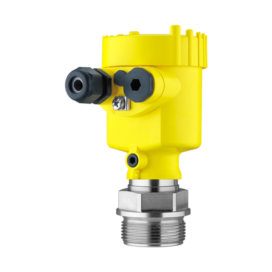
Page 7: Product Description
Housing cover, optionally available with display and adjustment module The components are available in different versions. Fig. 1: Example of a VEGABAR 52 with manometer connection G½ A according to EN 837 and plastic housing Housing cover with integrated display and adjustment module (optional) Housing with electronics... -
Page 8: Principle Of Operation
Software from 3.82 Principle of operation Application area VEGABAR 52 is a pressure transmitter for use in the paper, food processing and pharmaceutical industries as well as in water/sewage water plants. Depending on the version, it is used for level, gauge, absolute pressure or vacuum measurement. -
Page 9: Operation
The instrument can be adjusted with the following adjustment media: • With the display and adjustment module • with the suitable VEGA DTM in conjunction with an adjustment software according to the FDT/DTM standard, e.g. PACTware and Packaging, transport and storage Packaging Your instrument was protected by packaging during transport. -
Page 10: Accessories And Replacement Parts
Electronics module The electronics module is a replacement part for pressure transmitter VEGABAR. One version is available for each type of signal output. You find further information in the operating instructions "Electronics module VEGABAR series 50 and 60 " (Document-ID 30175). VEGABAR 52 • 4 … 20 mA... -
Page 11: Mounting
Fig. 3: Measures against moisture penetration Ventilation and pressure The ventilation of the electronics housing as well as the atmospheric compensation pressure compensation for the measuring cell are realised via a filter element in the area of the cable gland. VEGABAR 52 • 4 … 20 mA... - Page 12 Higher process temperatures often mean also higher ambient temperatures. Make sure that the upper temperature limits stated in chapter "Technical data" for the environment of the electronics hous- ing and connection cable are not exceeded. Fig. 5: Temperature ranges Process temperature Ambient temperature VEGABAR 52 • 4 … 20 mA...
-
Page 13: Mounting Steps
Sealing/Screwing in Use the seal fitting belonging to the instrument, or in case of NPT threaded versions connections, a high-resistance sealing material. → Screw VEGABAR 52 into the welded socket. Tighten the hexagon on the process fitting with a suitable wrench. Wrench size, see chapter "Dimensions". Warning: The housing must not be used to screw the instrument in! Applying tightening force can damage internal parts of the housing. - Page 14 180° to the wall mounting plate. Warning: The four screws of the socket housing must only be hand screwed. A torque > 5 Nm (3.688 lbf ft) can damage the wall mounting plate. VEGABAR 52 • 4 … 20 mA...
-
Page 15: Connecting To Power Supply
The data for power supply are specified in chapter "Technical data". Provide a reliable separation between the supply circuit and the mains circuits according to DIN EN 61140 VDE 0140-1. The VEGA power supply units VEGATRENN 149A Ex, VEGASTAB 690 as well as all VEGAMETs and VEGASCANs meet this requirement. -
Page 16: Connection Procedure
5. Insert the cable into the sensor through the cable entry 6. Lift the opening levers of the terminals with a screwdriver (see following illustration) 7. Insert the wire ends into the open terminals according to the wir- ing plan VEGABAR 52 • 4 … 20 mA... -
Page 17: Wiring Plan, Single Chamber Housing
12. Screw the housing cover back on The electrical connection is hence finished. Fig. 7: Connection steps 6 and 7 Wiring plan, single chamber housing The following illustrations apply to the non-Ex as well as to the Ex-ia version. VEGABAR 52 • 4 … 20 mA... -
Page 18: Wiring Plan - Version Ip 66/Ip 68, 1 Bar
Wiring plan - version IP 66/IP 68, 1 bar Wire assignment, con- nection cable Fig. 10: Wire assignment, connection cable brown (+) and blue (-) to power supply or to the processing system Shielding VEGABAR 52 • 4 … 20 mA... -
Page 19: Wiring Plan, External Housing With Version Ip 68
5 Connecting to power supply Wiring plan, external housing with version IP 68 Overview Fig. 11: VEGABAR 52 in IP 68 version 25 bar and axial cable outlet, external housing Terminal compartment, housing socket 1 2 3 4 Fig. 12: Connection of the sensor in the housing socket... -
Page 20: Switch-On Phase
Fig. 14: Wiring plan external electronics Voltage supply/Signal output Switch-on phase Switch-on phase After connecting VEGABAR 52 to power supply or after a voltage recurrence, the instrument carries out a self-check for approx. 30 seconds: • Internal check of the electronics •... -
Page 21: Set Up With The Display And Adjustment Module Plicscom
4. Screw housing cover with inspection window tightly back on Removal is carried out in reverse order. The display and adjustment module is powered by the sensor, an ad- ditional connection is not necessary. VEGABAR 52 • 4 … 20 mA... -
Page 22: Adjustment System
Adjustment system Fig. 16: Display and adjustment elements LC display Indication of the menu item number Adjustment keys • Key functions [OK] key: – Move to the menu overview – Confirm selected menu – Edit parameter VEGABAR 52 • 4 … 20 mA... -
Page 23: Setup Steps
[OK] will not be saved. Setup steps Level or process pres- VEGABAR 52 can be used for level as well as for process pressure sure measurement measurement. Default setting is level measurement. The mode can be changed in the adjustment menu. - Page 24 [->] (in the example m). 4. Confirm with [OK], the submenu "Density unit" appears. Unit of measurement Density unit ▶ kg/dm³ 5. Select the requested unit, e.g. kg/dm³ with [->] and confirm with [OK], the submenu "Density" appears. Unit of measurement Selection options: mbar, bar, psi, Pa, kPa, MPa, inHg, mmHg, inH VEGABAR 52 • 4 … 20 mA...
- Page 25 4. Set the requested mbar value with [+] and [->]. 5. Confirm with [+] and move to max. adjustment with [->]. The min. adjustment is finished. Information: For an adjustment with filling, simply enter the actual measured value indicated at the bottom of the display. Selection options: °C, °F. VEGABAR 52 • 4 … 20 mA...
- Page 26 If the adjustment ranges are exceeded, the message "Outside param- eter limits" appears. The editing procedure can be aborted with [ESC] or the displayed limit value can be accepted with [OK]. Process pressure measurement Set up VEGABAR 52 in the following sequence: Parameter adjustment "Process pressure meas- 1. Select application "Process pressure measurement" urement"...
- Page 27 4. Activate the selection with [OK] and select the requested unit with [->] (in the example mbar). 5. Confirm with [OK] and move to position correction with [->]. Selection options: mbar, bar, psi, Pa, kPa, MPa, inHg, mmHg, inH VEGABAR 52 • 4 … 20 mA...
- Page 28 For an adjustment with pressure, simply enter the actual measured value indicated at the bottom of the display. If the adjustment ranges are exceeded, the message "Outside param- eter limits" appears. The editing procedure can be aborted with [ESC] or the displayed limit value can be accepted with [OK]. Selection options: °C, °F. VEGABAR 52 • 4 … 20 mA...
- Page 29 Linear Enter the requested parameters via the appropriate keys, save your settings and jump to the next menu item with the [->] key. Caution: Note the following if the VEGABAR 52 with corresponding approval is used as part of an overfill protection system according to WHG (Water Resources Act): If a linearization curve is selected, the measuring signal is no longer linearly proportional to the level. This must be taken into consideration by the user, particularly when setting the switching point on the limit signal indicator.
- Page 30 Reset value Basic settings Zero/Min. adjustment Measuring range begin Span/Max. adjustment Measuring range end Density 1 kg/l Density unit kg/l Damping Linearization Linear Sensor-TAG Sensor With instruments with signal output 4 … 20 mA/HART VEGABAR 52 • 4 … 20 mA...
-
Page 31: Menu Schematic
Menu schematic Information: Depending on the version and application, the highlighted menu windows may not always be available. VEGABAR 52 • 4 … 20 mA... - Page 32 100 % = 100.0 Backlight ▼ Switched off Diagnostics Basic adjustment Display ▶ Diagnostics Service Info Peak value Sensor status Trend curve p-min.: -5.8 mbar p-max.: 167.5 mbar Start trend curve? T-min.: -12.5 °C T-max.: +85.5 °C VEGABAR 52 • 4 … 20 mA...
- Page 33 Copy sensor data Application ▼ Copy sensor data? Enable? Level Info Basic adjustment Display Diagnostics Service ▶ Info Instrument type Calibration date Last change using PC Sensor characteristics Software version Display now? Serial number VEGABAR 52 • 4 … 20 mA...
-
Page 34: Set Up With Pactware And Other Adjustment Programs
PACTware and the VEGA DTMs. Note: Keep in mind that for setup of VEGABAR 52, DTM-Collection in the actual version must be used. All currently available VEGA DTMs are included as a DTM Collection on a CD. -
Page 35: Maintenance And Fault Rectification
24 hour service hotline Should these measures not be successful, please call in urgent cases the VEGA service hotline under the phone no. +49 1805 858550. The hotline is available to you 7 days a week round-the-clock. Since we offer this service world-wide, the support is only available in the English language. -
Page 36: Calculation Of Total Deviation (According To Din 16086)
= √((F + (F perf With the analogue signal output there is also the error of the current output F Fault message can also appear if the pressure is higher than the nominal range. VEGABAR 52 • 4 … 20 mA... - Page 37 Pressure measurement in the pipeline 8 bar (800 KPa) Product temperature 50 °C, hence within the compensated range VEGABAR 52 with measuring range 10 bar Calculation of the set Turn Down: TD = 10 bar/8 bar, TD = 1.25 Basic accuracy digital output signal in percent: = √((F...
-
Page 38: Exchanging The Electronics Module
The electronics module with serial number includes order- specific data such as factory setting, seal material etc. These are not included in the electronics module without serial number. The serial number is stated on the type label of VEGABAR 52 or on the delivery note. Software update The software version of VEGABAR 52 can be determined as follows: •... -
Page 39: Instrument Repair
Attach the completed form and, if need be, also a safety data sheet outside on the packaging • Please ask the agency serving you for the address of your return shipment. You can find the respective contact data on our website www.vega.com under: "Company - VEGA worldwide" VEGABAR 52 • 4 … 20 mA... -
Page 40: Dismounting
WEEE directive. Correct disposal avoids negative effects on humans and the environ- ment and ensures recycling of useful raw materials. Materials: see chapter "Technical data" If you have no way to dispose of the old instrument properly, please contact us concerning return and disposal. VEGABAR 52 • 4 … 20 mA... -
Page 41: Supplement
Ʋ Ground terminal 316Ti/316L Ʋ Ohmic contact Between ground terminal and process fitting Ʋ Connection cable between transmitter and external electronics housing with IP 68 version Ʋ Type label support on connection PE hard cable VEGABAR 52 • 4 … 20 mA... - Page 42 Adjustment range of the min./max. adjustment relating to the nominal measuring range: Ʋ Percentage value -10 … 110 % Ʋ Pressure value -20 … 120 % Adjustment range of the zero/span adjustment relating to the nominal measuring range: Ʋ zero -20 … +95 % VEGABAR 52 • 4 … 20 mA...
- Page 43 0 … 25 bar/0 … 2500 kPa 130 bar/13000 kPa 0 bar abs. 0 … 60 bar/0 … 6000 kPa 200 bar/20000 kPa 0 bar abs. Nominal measuring ranges and overload capacity in psi Values less than -1 bar cannot be set. VEGABAR 52 • 4 … 20 mA...
- Page 44 Ʋ Relative humidity 45 … 75 % Ʋ Air pressure 860 … 1060 mbar/86 … 106 kPa (12.5 … 15.4 psig) Determination of characteristics Limit point adjustment according to IEC 61298-2 Characterstic curve Linear VEGABAR 52 • 4 … 20 mA...
- Page 45 Applies also to the analogue 4 … 20 mA current output and refers to the set span. Thermal change, current output < 0.05 %/10 K, max. < 0.15 %, each with -40 … +80 °C (-40 … +176 °F) Incl. non-linearity, hysteresis and non-repeatability. VEGABAR 52 • 4 … 20 mA...
-
Page 46: Ambient Conditions
DIN 11851) Ʋ Flange 316L PN 16, PN 40,150 lbs, 300 lbs, 600 lbs Ʋ Flange with extension 316L without PN specification, PN 16, PN 40 or 150 lbs, 300 lbs, 600 lbs Ʋ Flange flattened on both sides 316L PN 10 Ʋ Flange PVDF PN 16 VEGABAR 52 • 4 … 20 mA... - Page 47 Ʋ Wire cross-section 0.5 mm² (AWG 20) With process fitting PVDF, max. 100 °C (212 °F). Tested according to the guidelines of German Lloyd, GL directive 2. Tested according to EN 60068-2-27. Depending on the version M12 x 1, according to ISO 4400, Harting, 7/8" FF. VEGABAR 52 • 4 … 20 mA...
- Page 48 LC display in dot matrix Adjustment elements 4 keys Protection rating Ʋ unassembled IP 20 Ʋ mounted into the sensor without cover IP 40 Material Ʋ Housing Ʋ Inspection window Polyester foil Voltage supply Operating voltage Depending on the version M12 x 1, according to ISO 4400, Harting, 7/8" FF. VEGABAR 52 • 4 … 20 mA...
- Page 49 PACTware for applications according to SIL. Instruments with gauge pressure measuring ranges cannot detect the ambient pressure when submerged, e.g. in water. This can lead to falsification of the measured value. Only with instruments with absolute pressure ranges. VEGABAR 52 • 4 … 20 mA...
-
Page 50: Dimensions
Approvals Instruments with approvals can have different technical data depending on the version. For that reason the associated approval documents of these instruments have to be carefully noted. They are part of the delivery or can be downloaded under www.vega.com via "VEGA Tools" and "serial number search" as well as via "Downloads" and "Approvals". 10.2 Dimensions The following dimensional drawings represent only an extract of the possible versions. Detailed dimensional drawings can be downloaded on www.vega.com under "Downloads" and "Drawings". - Page 51 ½ NPT Fig. 23: Housing versions in protection IP 66/IP 68 (1 bar) - with integrated display and adjustment module the housing is 9 mm/0.35 in higher Single chamber version Double chamber version VEGABAR 52 • 4 … 20 mA...
- Page 52 Fig. 25: Housing versions in protection IP 66/IP 68 (1 bar) - with integrated display and adjustment module the housing is 9 mm/0.35 in higher Single chamber version, electropolished Single chamber version, precision casting Double chamber version, precision casting VEGABAR 52 • 4 … 20 mA...
- Page 53 110 mm x 90 mm (4.33" x 3.54") 40mm (1.57") Fig. 27: External housing - Stainless steel version Lateral cable outlet Axial cable outlet Seal 2 mm (0.079 in) - only with 3A approval VEGABAR 52 • 4 … 20 mA...
- Page 54 GM/GN Fig. 28: VEGABAR 52, threaded fitting: GV/GC = G½ A manometer connection EN 837, GL/GU = G½ A inner G¼ A, GS = G½ A inner G¼ A PVDF, GI = G½ A manometer connection volume-reduced, GM/GN = ½ NPT, GB = M20 x 1.5 manometer connection EN 837...
- Page 55 (2.68") Fig. 29: VEGABAR 52, threaded fitting: GG = G1½ A, GW = G1½ A PVDF, GN = 1½ NPT, GE = G2 A For the version with temperature range up to 150 °C/302 °F, the measure of length increases by 28 mm (1.1 in).
- Page 56 ø 105 mm ") Fig. 30: VEGABAR 52, hygienic fitting: CD/CC = Clamp 1"/Clamp 1½" acc. to DIN 32676, ISO 2852/316L, CA = Clamp 2", CA = Clamp 2½", LA = hygienic fitting with compression nut F40, AA = DRD...
- Page 57 RS/RT Fig. 31: VEGABAR 52, hygienic fitting: TA = Tuchenhagen Varivent DN 32, TB = Tuchenhagen Varivent DN 25, RA/ RB = bolting DN 40/DN 50 according to DIN 11851, RD = bolting DN 50 according to DIN 11864, RS/RT = SMS DN 38/DN 51 VEGABAR 52 •...
- Page 58 3” 150 lbs 7.5 " 0.94 " 6 " 8xø 0.75 " 5” 0.13 " Fig. 32: VEGABAR 52, flange connection Flange connection according to DIN 2501 Flange fitting according to ANSI B16.5 VEGABAR 52 • 4 … 20 mA...
- Page 59 ø 40 mm (1.58") Fig. 33: VEGABAR 52, threaded fitting for the paper industry: BA/BB = M44 x 1.25, BE = M56 x 1.25, DG = M48 x 1.25 with extension D 40 mm VEGABAR 52 • 4 … 20 mA...
- Page 60 (1.89...3.54") Fig. 34: VEGABAR 52, flange connection for the paper industry: TR = flange DN 50 with selectable tube, TS = flange DN 80 with selectable tube, FG = flange tube for ball valve fitting, EW = flange for manometer lug...
- Page 61 ø 48 mm (1.89") 50 mm 50 mm (1.97") (1.97") Fig. 35: VEGABAR 52, flange connection for the paper industry: FT = absolutely front-flush for headbox, EV = absolutely front-flush for headbox (flange 2-times flattened) VEGABAR 52 • 4 … 20 mA...
- Page 62 Les lignes de produits VEGA sont globalement protégées par des droits de propriété intellec- tuelle. Pour plus d'informations, on pourra se référer au site www.vega.com. VEGA lineas de productos están protegidas por los derechos en el campo de la propiedad indus- trial. Para mayor información revise la pagina web www.vega.com.
- Page 63 Zero adjustment 28 Hotline 35 Installation position 11 Linearization curve 29 Maintenance 35 Max. adjustment 26 Min. adjustment 25 Moisture 11 Mounting external housing 13 Position correction 25, 28 Pressure compensation 11 Process conditions 11 Recycling 40 VEGABAR 52 • 4 … 20 mA...
- Page 64 All statements concerning scope of delivery, application, practical use and operat- ing conditions of the sensors and processing systems correspond to the information available at the time of printing. Subject to change without prior notice © VEGA Grieshaber KG, Schiltach/Germany 2013...
Need help?
Do you have a question about the VEGABAR 52 and is the answer not in the manual?
Questions and answers