Vega VEGABAR 86 Operating Instructions Manual
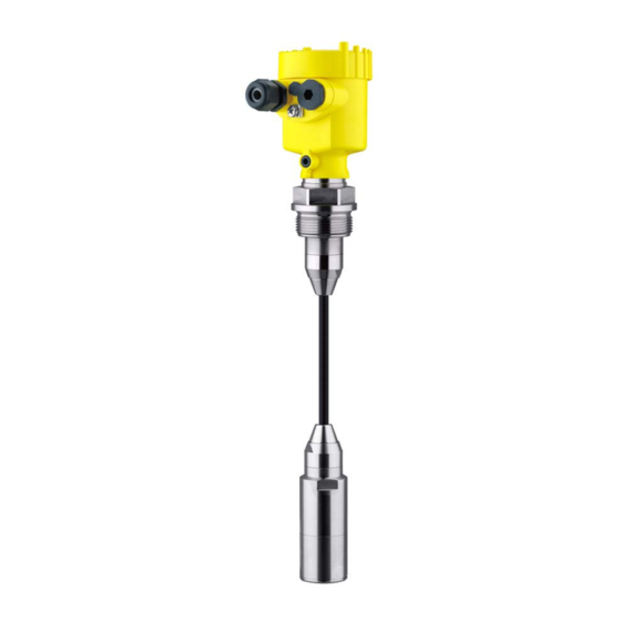
Submersible pressure transmitter with
ceramic measuring cell.
4...20 ma/hart
Hide thumbs
Also See for VEGABAR 86:
- Operating instructions manual (88 pages) ,
- Quick setup manual (24 pages) ,
- Operating instructions manual (72 pages)

Related Manuals for Vega VEGABAR 86


Summary of Contents for Vega VEGABAR 86
-
Page 1: Operating Instructions
Operating Instructions Submersible pressure transmitter with ceramic measuring cell VEGABAR 86 4 … 20 mA/HART Document ID: 45039... -
Page 2: Table Of Contents
Parameter adjustment - Quick setup ................34 Parameter adjustment - Extended adjustment..............34 Saving the parameterisation data ................... 47 Setup with PACTware ......................48 Connect the PC ......................48 Parameter adjustment ....................48 Saving the parameterisation data ................... 50 VEGABAR 86 • 4 … 20 mA/HART... - Page 3 11.6 Trademark ........................87 Safety instructions for Ex areas Take note of the Ex specific safety instructions for Ex applications. These instructions are attached as documents to each instrument with Ex approval and are part of the operating instructions manual. Editing status: 2018-05-22 VEGABAR 86 • 4 … 20 mA/HART...
-
Page 4: About This Document
Symbols used Document ID This symbol on the front page of this instruction refers to the Docu- ment ID. By entering the Document ID on www.vega.com you will reach the document download. Information, tip, note This symbol indicates helpful additional information. -
Page 5: For Your Safety
During work on and with the device the required personal protective equipment must always be worn. Appropriate use Model VEGABAR 86 is a pressure transmitter for level and gauge measurement. You can find detailed information about the area of application in chapter "Product description". -
Page 6: Eu Conformity
A Class 2 power supply unit has to be used for the installation in the USA and Canada. Environmental instructions Protection of the environment is one of our most important duties. That is why we have introduced an environment management system VEGABAR 86 • 4 … 20 mA/HART... - Page 7 2 For your safety with the goal of continuously improving company environmental pro- tection. The environment management system is certified according to DIN EN ISO 14001. Please help us fulfil this obligation by observing the environmental instructions in this manual: • Chapter "Packaging, transport and storage" • Chapter "Disposal" VEGABAR 86 • 4 … 20 mA/HART...
-
Page 8: Product Description
Alternatively, you can access the data via your smartphone: • Download the VEGA Tools app from the "Apple App Store" or the "Google Play Store" • Scan the Data Matrix code on the type label of the instrument or •... -
Page 9: Principle Of Operation
Optional instrument features are also described in this operating instructions manual. The respective scope of delivery results from the order specification. Principle of operation Measured variables The VEGABAR 86 is suitable for the measurement of the following process variables: • Level Fig. 2: Level measurement with VEGABAR 86... - Page 10 3 Product description Depending on the version, the VEGABAR 86 is also suitable for Electronic differential pressure electronic differential pressure measurement. For this, the instrument is combined with a slave sensor. Fig. 3: Electronic differential pressure measurement through Master/Slave combination You can find detailed information in the operating instructions of the respective slave sensor. The VEGABAR 86 is a submersible pressure transmitter for level Application area measurement in wells, basins and open vessels. Its great flexibility...
-
Page 11: Packaging, Transport And Storage
ISO 4180. The packaging of standard instruments consists of environment- friendly, recyclable cardboard. For special versions, PE foam or PE foil is also used. Dispose of the packaging material via specialised recycling companies. VEGABAR 86 • 4 … 20 mA/HART... -
Page 12: Accessories And Replacement Parts
PACTware with VEGA-DTM is required. You can find further information in the operating instructions "Interface adapter VEGACONNECT" (Document-ID 32628). Slave sensors Slave sensors of VEGABAR series 80 enable in conjunction with VEGABAR 86 an electronic differential pressure measurement. You can find further information in the operating instructions of the respective slave sensor. VEGABAR 86 • 4 … 20 mA/HART... - Page 13 3 Product description The VEGADIS 81 is an external display and adjustment unit for VEGA VEGADIS 81 plics sensors. ® For sensors with double chamber housing the interface adapter "VEGADIS adapter" is also required for VEGADIS 81. You can find further information in the operating instructions "VEGADIS 81" (Document-ID 43814).
- Page 14 "Welded socket and adapters" (Document-ID 48094). Electronics module The electronics module VEGABAR series 80 is a replacement part for pressure transmitters of VEGABAR series 80. There is a different version available for each type of signal output. You can find further information in the operating instructions "Elec- tronics module VEGABAR series 80" (Document-ID 45054). VEGABAR 86 • 4 … 20 mA/HART...
-
Page 15: Mounting
Suitability for the ambient The instrument is suitable for standard and extended ambient condi- conditions tions acc. to IEC/EN 61010-1. Depending on the transmitter, the VEGABAR 86 is supplied with a Transport and mounting protection protective cap or a transport and mounting protection. - Page 16 Make sure that the upper temperature limits stated in chapter "Technical data" for the environment of the electronics hous- ing and connection cable are not exceeded. Fig. 6: Temperature ranges Process temperature Ambient temperature VEGABAR 86 • 4 … 20 mA/HART...
-
Page 17: Ventilation And Pressure Compensation
Aluminium - single chamber Stainless steel single chamber (electropolished) Plastic double chamber Aluminium, stainless steel double chamber housing (precision casting) Filter element With the following instruments a blind plug is installed instead of the filter element: VEGABAR 86 • 4 … 20 mA/HART... - Page 18 An absolute pressure measuring cell is used so that no ventilation is required. With relative pressure measuring ranges, the ambient pressure is detected and compensated by a reference sensor in the electronics. VEGABAR 86 • 4 … 20 mA/HART...
-
Page 19: Level Measurement
Level measurement Measurement setup Keep the following in mind when setting up the measuring system: • Do not mount the instrument close to the filling stream or emptying area • Mount the instrument so that it is protected against pressure shocks from the stirrer VEGABAR 86 • 4 … 20 mA/HART... -
Page 20: External Housing
4 Mounting External housing Configuration Fig. 11: Arrangement measurement loop, external housing Sensor Connection cable sensor, external housing External housing Signal cable VEGABAR 86 • 4 … 20 mA/HART... -
Page 21: Connecting To Power Supply
You have to remove these plugs before electrical connection. NPT thread In the case of instrument housings with self-sealing NPT threads, it is not possible to have the cable entries screwed in at the factory. The VEGABAR 86 • 4 … 20 mA/HART... -
Page 22: Connecting
3. Loosen compression nut of the cable gland and remove blind plug 4. Remove approx. 10 cm (4 in) of the cable mantle, strip approx. 1 cm (0.4 in) of insulation from the ends of the individual wires VEGABAR 86 • 4 … 20 mA/HART... -
Page 23: Single Chamber Housing
10. Reinsert the display and adjustment module, if one was installed 11. Screw the housing lid back on The electrical connection is finished. Single chamber housing The following illustration applies to the non-Ex, Ex-ia and Ex-d ver- sion. VEGABAR 86 • 4 … 20 mA/HART... -
Page 24: Double Chamber Housing
The following illustrations apply to the non-Ex as well as to the Ex-ia version. Electronics compartment 4...20mA 6 7 8 Fig. 14: Electronics compartment - double chamber housing Internal connection to the terminal compartment For display and adjustment module or interface adapter VEGABAR 86 • 4 … 20 mA/HART... - Page 25 "Additional current output" First current output (I) - Voltage supply and signal output, sensor (HART) Additional current output (II) - Voltage supply and signal output (without HART) Ground terminal for connection of the cable screen VEGABAR 86 • 4 … 20 mA/HART...
-
Page 26: Ex-D-Ia Double Chamber Housing
Internal connection to the terminal compartment For display and adjustment module or interface adapter Terminal compartment 4...20mA Fig. 19: Connection compartment - Ex-d-ia double chamber housing Voltage supply, signal output Ground terminal for connection of the cable screen VEGABAR 86 • 4 … 20 mA/HART... -
Page 27: Double Chamber Housing With Vegadis-Adapter
Fig. 21: View to the plug connector M12 x 1 Pin 1 Pin 2 Pin 3 Pin 4 Contact pin Colour, connection ca- Terminal, electronics ble in the sensor module Pin 1 Brown Pin 2 White Pin 3 Blue Pin 4 Black VEGABAR 86 • 4 … 20 mA/HART... -
Page 28: Housing Ip 66/Ip 68 (1 Bar)
Brown (+) and blue (-) to power supply or to the processing system Shielding External housing Terminal compartment, housing socket 1 2 3 4 Fig. 23: Connection of the process component in the housing base Yellow White Black Shielding Breather capillaries VEGABAR 86 • 4 … 20 mA/HART... - Page 29 Fig. 25: Electronics and terminal compartment - single chamber housing Voltage supply, signal output For display and adjustment module or interface adapter For external display and adjustment unit or Slave sensor Ground terminal for connection of the cable screen VEGABAR 86 • 4 … 20 mA/HART...
-
Page 30: Connection Example
5 Connecting to power supply Connection example Connection example, ad- ditional current output 4...20mA 4...20mA Fig. 26: Connection example VEGABAR 86 additional current output Supply and signal circuit, sensor Signal circuit, additional current output Input card PLC Sensor Circuit Input card PLC... -
Page 31: Set Up With The Display And Adjustment Module
The display and adjustment module is powered by the sensor, an ad- ditional connection is not necessary. Fig. 27: Installing the display and adjustment module in the electronics compart- ment of the single chamber housing VEGABAR 86 • 4 … 20 mA/HART... -
Page 32: Adjustment System
Adjustment keys • Key functions [OK] key: – Move to the menu overview – Confirm selected menu – Edit parameter – Save value • [->] key: – Change measured value presentation – Select list entry VEGABAR 86 • 4 … 20 mA/HART... -
Page 33: Measured Value Indication
"English". Approx. 60 minutes after the last pressing of a key, an automatic reset to measured value indication is triggered. Any values not confirmed with [OK] will not be saved. Measured value indication Measured value indica- With the [->] key you can move between three different indication tion modes. VEGABAR 86 • 4 … 20 mA/HART... -
Page 34: Parameter Adjustment - Quick Setup
[->] or [ESC] keys or automatically after 3 s Note: You can find a description of the individual steps in the quick setup guide of the sensor. You can find "Extended adjustment" in the next sub-chapter. Parameter adjustment - Extended adjustment For technically demanding measuring points, you can carry out extended settings in "Extended adjustment". VEGABAR 86 • 4 … 20 mA/HART... - Page 35 In this menu item you activate/deactivate the slave sensor for elec- tronic differential pressure and select the application. VEGABAR 86 can be used for process pressure and level measure- ment. The setting in the delivery status is process pressure measure- ment. The mode can be changed in this adjustment menu.
- Page 36 With relative pressure measuring cells a manual offset can also be carried out. If the actual measured value should be taken over as correction value during automatic position correction, this value must not be influ- enced by product coverage or static pressure. VEGABAR 86 • 4 … 20 mA/HART...
- Page 37 Parameterization example VEGABAR 86 always measures pressure independently of the pro- cess variable selected in the menu item "Application". To output the selected process variable correctly, an allocation of the output signal to 0 % and 100 % must be carried out (adjustment).
- Page 38 5. Save settings with [OK] The max. adjustment is finished. For an adjustment with filling, simply enter the actual measured value indicated at the bottom of the display. Setup - Damping To damp process-dependent measured value fluctuations, set an integration time of 0 … 999 s in this menu item. The increment is 0.1 s. VEGABAR 86 • 4 … 20 mA/HART...
- Page 39 Setup - Current output In the menu item "Current output Min./Max.", you determine the reac- (Min./Max.) tion of the current output during operation. The default setting is min. current 3.8 mA and max. current 20.5 mA. VEGABAR 86 • 4 … 20 mA/HART...
- Page 40 Polish • Czech • Turkish In delivery status, the VEGABAR 86 is set to English. Display - Displayed value In this menu item, you define which measured value is displayed. 1 and 2 The setting in the delivery status for the display value is "Lin. percent". Display - Display format...
- Page 41 Diagnosis - Simulation In this menu item you can simulate measured values. This allows the signal path to be tested, e.g. through downstream indicating instru- ments or the input card of the control system. VEGABAR 86 • 4 … 20 mA/HART...
- Page 42 The following table shows the default values of the instrument. De- pending on the instrument version or application, all menu items may not be available or some may be differently assigned: VEGABAR 86 • 4 … 20 mA/HART...
- Page 43 Number of positions after the decimal point, automatically Backlight Switched on Reset - Diagnosis Menu item Parameter Default value Sensor status Peak value Pressure Actual measured value Temperature Actual temperature values from measuring cell, elec- tronics Process pressure Simulation VEGABAR 86 • 4 … 20 mA/HART...
-
Page 44: Instrument Settings
If the data do not match, a fault message is outputted or the function is blocked. The data are saved only after release. VEGABAR 86 • 4 … 20 mA/HART... - Page 45 4 mA (0 %) and 20 mA (100 %) of the current output refer to. If the measuring cell temperature is selected as measured variable, then e.g. 0 °C refers to 4 mA and 100 °C to 20 mA. VEGABAR 86 • 4 … 20 mA/HART...
- Page 46 PC. Info - Sensor character- In this menu item, the features of the sensor such as approval, pro- istics cess fitting, seal, measuring range, electronics, housing and others are displayed. VEGABAR 86 • 4 … 20 mA/HART...
-
Page 47: Saving The Parameterisation Data
In the display and adjust- If the instrument is equipped with a display and adjustment module, ment module the parameter adjustment data can be saved therein. The procedure is described in menu item "Copy device settings". VEGABAR 86 • 4 … 20 mA/HART... -
Page 48: Setup With Pactware
Note: With power supply units with integrated HART resistance (internal resistance approx. 250 Ω), an additional external resistance is not necessary. This applies, e.g. to the VEGA instruments VEGATRENN 149A, VEGAMET 381, VEGAMET 391. Common Ex separators are also usually equipped with a sufficient current limiting resistance. In such cases, the interface converter can be connected parallel to the 4 …... - Page 49 The standard version is available as a download under www.vega.com/downloads and "Software". The full version is avail- able on CD from the agency serving you. VEGABAR 86 • 4 … 20 mA/HART...
-
Page 50: Saving The Parameterisation Data
7 Setup with PACTware Saving the parameterisation data We recommend documenting or saving the parameterisation data via PACTware. That way the data are available for multiple use or service purposes. VEGABAR 86 • 4 … 20 mA/HART... -
Page 51: Set Up With Other Systems
They can then be transferred to a Field Communicator. In the HART communication, the Universal Commands and a part of the Common Practice Commands are supported. VEGABAR 86 • 4 … 20 mA/HART... -
Page 52: Diagnosis, Asset Management And Service
Event memory Up to 500 events are automatically stored with a time stamp in the sensor (non-deletable). Each entry contains date/time, event type, event description and value. Event types are for example: • Modification of a parameter VEGABAR 86 • 4 … 20 mA/HART... -
Page 53: Asset Management Function
Plan in maintenance for the instrument because a failure is expected in the near future (e.g. due to buildup). This status message is inactive by default. It can be activated by the user via PACTware/DTM or EDD. VEGABAR 86 • 4 … 20 mA/HART... - Page 54 Error in the EEPROM bration • • F261 Error during setup Repeat setup Bit 11 of Byte 0 … 5 • • Error when carrying out a reset Repeat reset Error in the instru- ment settings VEGABAR 86 • 4 … 20 mA/HART...
- Page 55 • M500 The data could not be restored Repeat reset Bit 0 of • during the reset to delivery Load XML file with sensor data Byte 14 … 24 Error in the delivery status into the sensor status VEGABAR 86 • 4 … 20 mA/HART...
-
Page 56: Rectify Faults
Operating voltage too low, load resist- Check, adapt if necessary ance too high • • Current signal greater than Sensor electronics defective Exchange the instrument or send it in 22 mA, less than 3.6 mA for repair VEGABAR 86 • 4 … 20 mA/HART... -
Page 57: Exchange Process Module On Version Ip 68 (25 Bar)
24 hour service hotline Should these measures not be successful, please call in urgent cases the VEGA service hotline under the phone no. +49 1805 858550. The hotline is also available outside normal working hours, seven days a week around the clock. -
Page 58: Exchanging The Electronics Module
9 Diagnosis, asset management and service Fig. 36: VEGABAR 86 in IP 68 version, 25 bar and lateral cable outlet, external housing Process module Plug connector Cable assembly Connection cable External housing 3. Loosen the plug connector 4. Mount the new process module on the measuring point 5. -
Page 59: How To Proceed If A Repair Is Necessary
You can find an instrument return form as well as detailed informa- tion about the procedure in the download area of our homepage: www.vega.com. By doing this you help us carry out the repair quickly and without having to call back for needed information. In case of repair, proceed as follows: •... -
Page 60: Dismount
Pass the instrument directly on to a spe- cialised recycling company and do not use the municipal collecting points. These may be used only for privately used products according to the WEEE directive. VEGABAR 86 • 4 … 20 mA/HART... -
Page 61: Supplement
Ʋ Seal between housing and housing lid Silicone SI 850 R, NBR silicone-free, EPDM cleaned Ʋ Inspection window in housing cover Polycarbonate, UL746-C listed (with Ex-d version: glass) Ʋ Ground terminal 316L EPDM cleaned in conjunction with FEP cable with coating-compatible version VEGABAR 86 • 4 … 20 mA/HART... - Page 62 50 Nm (36.88 lbf ft) Input variable The specifications are only an overview and refer to the measuring cell. Limitations due to the material and version of the process fitting as well as the selected pressure type are possible. The specifications on the nameplate apply. Nominal measuring ranges and overload capability in bar/kPa Nominal range Overload capacity, max. pressure Overload capacity, min. pressure Gauge pressure Between transmitter and external electronics housing. VEGABAR 86 • 4 … 20 mA/HART...
- Page 63 0 … 150 psi 1300 psi 0 psi 0 … 300 psi 1900 psi 0 psi 0 … 900 psig 2900 psig 0 psi Adjustment ranges Specifications refer to the nominal measuring range, pressure values lower than -1 bar cannot be Min./Max. adjustment: Ʋ Percentage value -10 … 110 % VEGABAR 86 • 4 … 20 mA/HART...
- Page 64 Fault signal, current output (adjustable) Last valid measured value, ≥ 21 mA, ≤ 3.6 mA Max. output current 21.5 mA Starting current ≤ 10 mA for 5 ms after switching on, ≤ 3.6 mA Load Load resistor, see chapter "Voltage supply" Last valid measured value not possible with SIL. The output values can be assigned individually. VEGABAR 86 • 4 … 20 mA/HART...
- Page 65 Via the additional current output (4 mA = 0 °C, 20 mA = 100 °C) Ʋ Digital Depending on the electronics version via the HART, Profibus PA, Foundation Fieldbus or Modbus signal Reference conditions and influencing variables (according to DIN EN 60770-1) Reference conditions according to DIN EN 61298-1 Ʋ Temperature +15 … +25 °C (+59 … +77 °F) VEGABAR 86 • 4 … 20 mA/HART...
- Page 66 4 … 20 mA and refers to the set span. Turn down (TD) is the ratio "nominal measuring range/set span". The thermal change of the zero signal and output span corresponds to the value F in chapter "Calculation of the total deviation (according to DIN 16086)". Ceramic measuring cell - Standard Fig. 38: Basic temperature error F at TD 1 : 1 TBasis VEGABAR 86 • 4 … 20 mA/HART...
- Page 67 80°C 20°C -0,15 % -0,3 % Fig. 39: Thermal change, current output Long-term stability (according to DIN 16086) Applies to the respective digital signal output (e.g. HART, Profibus PA) as well as to analogue cur- rent output 4 … 20 mA under reference conditions. Specifications refer to the set span. Turn down (TD) is the ratio nominal measuring range/set span. VEGABAR 86 • 4 … 20 mA/HART...
-
Page 68: Ambient Conditions
FFKM (Kalrez 6375) -10 … +100 °C (+14 … +212 °F) Connection tube FKM (VP2/A) -20 … +100 °C (-4 … +212 °F) EPDM (A+P 75.5/KW75F) FFKM (Kalrez 6375) -10 … +100 °C (+14 … +212 °F) VEGABAR 86 • 4 … 20 mA/HART... - Page 69 Wires, strain relief, breather capillaries, screen braiding, metal foil, mantle Depending on the instrument version 2 g with housing version stainless steel double chamber IP 66/IP 68 (0.2 bar), only with absolute pressure. Breather capillaries not with Ex-d version. VEGABAR 86 • 4 … 20 mA/HART...
- Page 70 [OK], [->], [+], [ESC] Ʋ Switch Bluetooth On/Off Bluetooth interface Ʋ Standard Bluetooth smart Ʋ Effective range 25 m (82.02 ft) Protection rating Ʋ unassembled IP 20 Ʋ mounted in the housing without lid IP 40 VEGABAR 86 • 4 … 20 mA/HART...
- Page 71 < 0.1 K Accuracy ±3 K Voltage supply Operating voltage U Ʋ Non-Ex instrument 9.6 … 35 V DC Ʋ Ex-d instrument 9.6 … 35 V DC Ʋ Ex-ia instrument 9.6 … 30 V DC VEGABAR 86 • 4 … 20 mA/HART...
- Page 72 2000 m (6562 ft) Ʋ with connected overvoltage protection up to 5000 m (16404 ft) Galvanic separation between electronics and metal housing parts Protection rating IP 66/IP 68 (0.2 bar) only in conjunction with absolute pressure. VEGABAR 86 • 4 … 20 mA/HART...
-
Page 73: Calculation Of The Total Deviation
Level measurement in a water reservoir, 1,600 mm height corresponds to 0.157 bar (157 kPa), medium temperature 50 °C VEGABAR 86 with measuring range 0.4 bar, deviation < 0.1 %, meas. cell ø 28 mm 1. Calculation of the Turn down TD = 0.4 bar/0.157 bar, TD = 2.6 : 1... - Page 74 Accuracy class Non-linearity, hysteresis and non-repeatability TD ≤ 5 : 1 TD > 5 : 1 0.1 % < 0.1 % < 0.02 % x TD Tab. 26: Determination of the deviation from table: F = 0.1 % VEGABAR 86 • 4 … 20 mA/HART...
- Page 75 = 0.26 % = 0.2 % = 0.15 % = √(0.26 %) + (0.1 %) ) + (0.15 %) perf = 0.32 % perf - 2. step: Total deviation F total total perf stab VEGABAR 86 • 4 … 20 mA/HART...
-
Page 76: Dimensions
The thermal change of the current output is in this example is negligible. 11.4 Dimensions The following dimensional drawings represent only an extract of the possible versions. Detailed dimensional drawings can be downloaded at www.vega.com under "Downloads" and "Drawings". Plastic housing ~ 69 mm ~ 84 mm (2.72") - Page 77 Fig. 43: Housing version with protection rating IP 66/IP 68 (1 bar) - with integrated display and adjustment module the housing is 9 mm/0.35 in higher Aluminium - single chamber Aluminium - double chamber VEGABAR 86 • 4 … 20 mA/HART...
- Page 78 Fig. 45: Housing version with protection rating IP 66/IP 68 (1 bar) - with integrated display and adjustment module the housing is 9 mm/0.35 in higher Stainless steel single chamber (electropolished) Stainless steel single chamber (precision casting) Stainless steel double chamber housing (precision casting) VEGABAR 86 • 4 … 20 mA/HART...
- Page 79 ø 80 mm (3.15") M20x1,5/ ½ NPT Fig. 46: Housing version with protection rating IP 69K - with integrated display and adjustment module the housing is 9 mm/0.35 in higher Stainless steel single chamber (electropolished) VEGABAR 86 • 4 … 20 mA/HART...
- Page 80 (1.64") ~ 66 mm (2.60") 110 mm x 90 mm (4.33" x 3.54") Fig. 47: VEGABAR 86, IP 68 version with external housing Lateral cable outlet Axial cable outlet Plastic single chamber Stainless steel single chamber Seal 2 mm (0.079 in), (only with 3A approval)
- Page 81 ø 29 mm (0.32") (1.14") ø 32 mm (1.26") Fig. 48: VEGABAR 86, sensor 32 mm with straining clamp With threaded fitting G1½ (1½ NPT) With thread G1½ (1½ NPT) with direct cable outlet VEGABAR 86 • 4 … 20 mA/HART...
- Page 82 1NPT ø 8 mm (0.32") ø 22 mm (0.87") Fig. 49: VEGABAR 86, sensor 22 mm with straining clamp With threaded fitting G1½ (1½ NPT) With thread G1½ (1½ NPT) with direct cable outlet VEGABAR 86 • 4 … 20 mA/HART...
- Page 83 ø 44 mm ø 37 mm (1.73") (1.46") Fig. 50: VEGABAR 86, plastic version PVDF, with threaded fitting G1½ (1½ NPT) PVDF, with thread G1½ (1½ NPT) PE coated, with thread G1½ (1½ NPT) VEGABAR 86 • 4 … 20 mA/HART...
- Page 84 0.75 " 0.12 " 4" 10" 1 .25" 7.87 " 8xø0.63 " 6.19 " Fig. 51: VEGABAR 86, flange connection (example: sensor 32 mm) Flanges according to DIN 2501 Flanges according to ASME B16.5 VEGABAR 86 • 4 … 20 mA/HART...
- Page 85 ø 92 mm (3.62") ø 8 mm (0.32") ø 32 mm (1.26") Fig. 52: VEGABAR 86, hygienic fittings Clamp 2" (ø 64 mm) PN 16 DIN 32676, ISO 2852 Slotted nut DN 50 VEGABAR 86 • 4 … 20 mA/HART...
- Page 86 SW 27 mm SW 41 mm (1.06") (1.61") G½ ø 22 mm G¼ (0.87 ") Fig. 53: VEGABAR 86, threaded version Thread G½ internal G¼ Thread ½ NPT, hole ø 11 mm Thread G1 VEGABAR 86 • 4 … 20 mA/HART...
-
Page 87: Industrial Property Rights
Les lignes de produits VEGA sont globalement protégées par des droits de propriété intellec- tuelle. Pour plus d'informations, on pourra se référer au site www.vega.com. VEGA lineas de productos están protegidas por los derechos en el campo de la propiedad indus- trial. Para mayor información revise la pagina web www.vega.com. - Page 88 Maintenance 52 Measured value memory 52 Measurement setup – In the open vessel 19 NAMUR NE 107 53 Peak value indicator 41 Position correction 36 Pressure compensation 17, 18, 19 – Ex-d 18 VEGABAR 86 • 4 … 20 mA/HART...
- Page 89 Notes VEGABAR 86 • 4 … 20 mA/HART...
- Page 90 Notes VEGABAR 86 • 4 … 20 mA/HART...
- Page 91 Notes VEGABAR 86 • 4 … 20 mA/HART...
- Page 92 Subject to change without prior notice © VEGA Grieshaber KG, Schiltach/Germany 2018 VEGA Grieshaber KG Phone +49 7836 50-0 Am Hohenstein 113...
Need help?
Do you have a question about the VEGABAR 86 and is the answer not in the manual?
Questions and answers