
Related Manuals for ITech IT6121B


Summary of Contents for ITech IT6121B
- Page 1 High Speed and High Accuracy Programmable Power Supply Series IT6100B User’s Manual Model: IT6121B/IT6122B/IT6123B/IT6132B/ IT6133B/IT6162B/IT6164B Version: V1.1...
- Page 2 IT6100B User’s Manual Notices Warranty Safety Notices © Itech Electronics, Co., Ltd. 2017 The materials contained in this No part of this manual may be document are provided “as is”, and reproduced in any form or by any means is subject to change, without prior (including electronic storage and notice, in future editions.
-
Page 3: Limitation Of Warranty
PREPAID. And ITECH will pay for return of the product to customer. If the product is returned to ITECH for warranty service from overseas, all the freights, duties and other taxes shall be on the account of customer. Limitation of Warranty This Warranty will be rendered invalid if the product is: ... -
Page 4: Safety Precautions
Failure to comply with these precautions or specific warnings elsewhere in this manual will constitute a default under safety standards of design, manufacture and intended use of the instrument. ITECH assumes no liability for the customer’s failure to comply with these precautions. -
Page 5: Waste Electrical And Electronic Equipment (Weee) Directive
With reference to the equipment classifications described in the Annex I of the WEEE Directive, this instrument is classified as a “Monitoring and Control Instrument” product. To return this unwanted instrument, contact your nearest ITECH office. Copyright © ITECH Electronics Co., Ltd. -
Page 6: Compliance Information
Connection of the instrument to a test object may produce radiations beyond the specified limit. Use high-performance shielded interface cable to ensure conformity with the EMC standards listed above. Safety Standard IEC 61010-1:2010/ EN 61010-1:2010 Copyright © ITECH Electronics Co., Ltd. -
Page 7: Table Of Contents
4.1 Specification ..............................31 Chapter5 Remote Operation Mode ................. 35 5.1 RS232 interface ..............................35 5.2 USB interface ..............................36 5.3 GPIB interface ..............................37 5.4 Communication protocol ..........................37 Appendix ........................... 38 Specifications of Red and Black Test Lines......................38 Copyright © ITECH Electronics Co., Ltd. -
Page 8: Chapter1 Inspection And Installation
Please select appropriate space for installation based on the electronic load size. IT6100B series power supply different models are not the same size, the detail size of the power supply are shown as below. Copyright © ITECH Electronics Co., Ltd. - Page 9 Inspection and Installation IT6121B/IT6122B/IT6123B/IT6132B/IT6133B Models Dimension: Width: 214.5 mm Height: 88.2 mm Depth: 354.6 mm Detailed Dimension Drawing Copyright © ITECH Electronics Co., Ltd.
- Page 10 Inspection and Installation IT6162B Model Dimension: Width: 482.5 mm Height: 88.2 mm Depth: 650 mm Detailed Dimension Drawing Copyright © ITECH Electronics Co., Ltd.
-
Page 11: Rack Mounting
Depth: 664.12 mm Detailed Dimension Drawing 1.3 Rack Mounting IT6100B series can be mounted on a standard 19” rack. ITECH provides user with IT-E151 rack, as a mount kit. The detailed operation please refer to the User Manual of your mount kit. - Page 12 Any misuse voids the warranty of this product. Connecting AC Input IT6121B/IT6122B/IT6123B/IT6132B/IT6133B Connect standard power cord to the power supply input terminal. IT6162B/IT6164B AC input connector as follows.
- Page 13 Connect the three terminals red to line (L), black to neutral (N), and yellow to ground (G) on the other end of the power cord to your AC distribution panel. Copyright © ITECH Electronics Co., Ltd.
-
Page 14: Chapter2 Quick Reference
Rich SCPI commands, convenient to built intelligent test platform. Provide free remote control software with strong function saving secondary development time. Model Voltage current Power IT6121B 100W IT6122B IT6123B 1.2A 86.4W IT6132B 150W Copyright © ITECH Electronics Co., Ltd. -
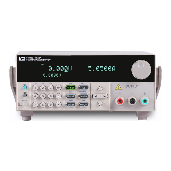
Page 15: Front Panel Introduction
4. Numeric keys, esc button 5. Function keys 6. up/down, left/right key 7. output terminals Front panel of IT6162B/IT6164B. 1. Power switch 2. VFD display 3. Shift and Local key 4. Numeric keys, esc button 5. Function keys Copyright © ITECH Electronics Co., Ltd. -
Page 16: Rear Panel Introduction
2. RS232 interface 3. Qucik connect terminal for remote sensing and DVM terminal and external control port 4. USB interface 5. GPIB interface 6. AC power inlet and fuse compartment Rear panel of IT6162B. Copyright © ITECH Electronics Co., Ltd. - Page 17 1. Ventilation holes 2. DVM terminal and external control port 3. RS232 interface 4. USB interface 5. GPIB interface 6. Fuse 7. AC power inlet 8. output terminals and qucik connect terminal for remote sensing Copyright © ITECH Electronics Co., Ltd.
-
Page 18: Keyboard Introduction
Up/down key to overturn the menu items or increase/decrease the setting value. Quit the operation Numerical keys/Secondary Shift Functions: Set the range of the mΩ Meter to 0.1W (0.1W) Set the range of the mΩ Meter to 1W (1W) Copyright © ITECH Electronics Co., Ltd. -
Page 19: Function Description Of Vfd Status Indicators
1. Correctly connect the power cord. Press Power key to start up. 2. After self-test, if the power supply is normal, then VFD will display the output voltage and current status as below: 0.000V 0.0000A 0.0001V Copyright © ITECH Electronics Co., Ltd. - Page 20 Products Specification (110VAC) Specification (220VAC) IT6121B T 5A T2.5A IT6122B T 5A T2.5A IT6123B T 5A T2.5A IT6132B T 5A T2.5A IT6133B T 5A T2.5A IT6162B 20AT 10AT IT6164B Does support 15AT 110VAC input Copyright © ITECH Electronics Co., Ltd.
- Page 21 Quick Reference 3) After replacement, install the fuse box back to original position, as shown below. NOTE Fuse of IT6162B/IT6164B can unscrew directly by hand. Copyright © ITECH Electronics Co., Ltd.
-
Page 22: Chapter3 Basic Operation
3 solutions to set the constant voltage value. Solution1: Step1: Power on the IT6100B series instrument V-set V-set Step2: Press Step2: Press to move the cursor and press the keys to change the value Enter Step3: Press to confirm. Solution2: Copyright © ITECH Electronics Co., Ltd. -
Page 23: Setting The Current
When output is on, the indicater CV/CC on the VFD will be lit. On/Off Note: make sure you have connected power supply well first, then press button. Copyright © ITECH Electronics Co., Ltd. -
Page 24: Set Mode And Meter Mode
Press CONFIG MENU toconfirm Initialize Memory Out_Recal Enter to select”Memory”,press Press MEMORY GROUP SET confirm group = 0 Press numeric key to set the memory group to 2 MEMORY GROUP SET group = 2 Copyright © ITECH Electronics Co., Ltd. -
Page 25: Trigger Operation
Disable this function. The parameters are the default set when power up. Buzzer KEY BUZZER Keypad sound setting Enable key sound Off(default) Disable key sound Knob KNOB LOCK Enable/disable the rotary knob. Copyright © ITECH Electronics Co., Ltd. - Page 26 OUTPUT MODE… OutMode Set Output Mode Volt-Wave Prio Volt Wave Prio Curr-Wave Prio Curr Wave Prio Range RANGE MENU Set Output Range Low_Range Low range High_Range High range RECALL LIST Edit_List FILE Recall 1 Copyright © ITECH Electronics Co., Ltd.
-
Page 27: Menu Function
38400, 57600, 115.2K.Data bit is 8, Check digit have three choices: NONE,ODD,EVEN. Before you begin to carry out communication, please make sure the configure in our unit agrees with PC configure. More information please refer to chapter 6. Copyright © ITECH Electronics Co., Ltd. - Page 28 TRIgger command to the power supply Immediat: You can trigger the power supply by sending the command TRIG: IMM in any case, regardless of the trigger source selected in the current menu. The default set is Manual Copyright © ITECH Electronics Co., Ltd.
- Page 29 2. Press to select Port, press to confirm. 3. VFD display Trigger RI/DFI Digital, Press to select RI/DFI, Enter press to confirm. 4. VFD return to Comm Port Trig RI DFI, press to select DFI, Copyright © ITECH Electronics Co., Ltd.
- Page 30 >NO,all setting in the menu will remain unchanged. OutMode (IT6162B/IT6164B Specific function) This item is used to set the power supply output mode, including Volt-Wave Prio (voltage priority) mode and Curr-Wave Prio (current priority) mode. Under voltage Copyright © ITECH Electronics Co., Ltd.
- Page 31 Total step range:2~999(1 can LIST STEP SET Set List step count Total Step= 3 be set, but it makes no sense) Set the voltage for the LIST VOLTAGE SET Voltage range: 0~Vmax 1th step step001=12.000V Copyright © ITECH Electronics Co., Ltd.
- Page 32 ( Shift) + L5:00002:01 count (Trigger) to trigger Enter Enter The 2nd step of the 2nd Press ( Shift) + L5:00002:02 count (Trigger) to trigger L5:EE Press Esc to escape the List in any case. Copyright © ITECH Electronics Co., Ltd.
-
Page 33: Ovp
(Lock) once again will relieve key lock function. (Shift)+ 3.12 Terminals at rear panel The terminals at rear panel of IT6100B include: remote sense, DVM and milliohm meter, I/O port. The terminals at rear panel of IT6121B/IT6122B/IT6123B/IT6132B/IT6133B. Copyright © ITECH Electronics Co., Ltd. -
Page 34: Remote Sense
2. Connect the positive and negative terminals on the front panel or the Drive + Drive- terminalson the rear panel to the device under test (DUT). Wiring Schematic Diagram Local Measurement IT6121B/IT6122B/IT6123B/IT6132B/IT6133B is as follows: Wiring Schematic Diagram of Local Measurement of IT6162B/IT6164B is as follows: Copyright © ITECH Electronics Co., Ltd. - Page 35 The connectors are in the rear panel. The voltage value is displayed on the bottom left field of the display. The operation to adjust the voltage meter range is: I-set I-set (Menu)to menu 1. Press (Shift)+ Enter 2. Press to enter System menu, press to confirm Copyright © ITECH Electronics Co., Ltd.
- Page 36 The wires at the positive and negative terminal of the DVM should be connected at the root of the resistance to be measured! Swithing operation of DVM and milliohm meter Meter Meter Press (Shift)+ (DVM/DRM) 0.0000V 0.00000A 0.000Ω Range: 10W Copyright © ITECH Electronics Co., Ltd.
-
Page 37: Power Information
(Shift) + set the range to 10W 3.13 Power information The information include: Model, program version, serial number (SN). Operation to check: Press (Shift) + (Info) to check model and program version, and check SN. Copyright © ITECH Electronics Co., Ltd. -
Page 38: Chapter4 Specification
IT6100B User’s Manual Chapter4 Specification 4.1 Specification IT6121B IT6122B IT6123B IT6132B IT6133B Parameter Output 0-20V 0-32V 0-72V 0-30V 0-60V Ratings voltage 0-5A 0-3A 0-1.2A 0-5A 0-2.5A current 100W 86.4W 150W 150W power <0.01%+1mV <0.01%+1mV <0.01%+1mV <0.01%+1mV <0.01%+2mV Line voltage regulation <0.05%+1mA... - Page 39 Setup stability -8h Voltage 0.015%+2mV (%of Output +Offset) Current 0.15%+20mA Readback stability-30min Voltage 0.01%+2mV (%of Output +Offset) Current 0.1%+20mA Readback stability -8h Voltage 0.015%+2mV (%of Output +Offset) Current 0.15%+20mA Fuse specification 10A(Voltage3,4) / 20A(Voltage1,2) Copyright © ITECH Electronics Co., Ltd.
- Page 40 25℃±5℃) ≤0.05%+15mA Current (%of Output+Offset) ≤ 5mVp-p / 1.2 mV rms Voltage Ripple (20Hz -20MHz) ≤15mArms Current Voltage 0.01%+2mV Tem coefficient (%of Output/℃+Offset) Current 0.01%+20mA Voltage 0.01%+2mV Readback Tem coefficient (%of Output/℃+Offset) Current 0.01%+15mA Copyright © ITECH Electronics Co., Ltd.
- Page 41 (% of Output +Offset) Display stability -8 h 0.02%+2.5 mV (% of Output +Offset) -40V - +40V Measurement range < 200Vdc Input Common-mode voltage *The above specifications may be subject to change without prior notice. Copyright © ITECH Electronics Co., Ltd.
-
Page 42: Chapter5 Remote Operation Mode
DB-25 connector at one end and the other side is a DB-9(not blank modem cable) Base Description number No conjunction TXD, data transmission RXD, data receiving RS232 Pins of Plug No conjunction GND, grounding No conjunction CTS, clear to send RTS, request to send Copyright © ITECH Electronics Co., Ltd. -
Page 43: Usb Interface
Interface receives MsgID = TRIGGER USBTMC order information, and will pass TRIGGER order to the functional layer. Power USB488 device functions described as follows: Devices can read all of the mandatory SCPI orders. Device is SR1 enabled. Copyright © ITECH Electronics Co., Ltd. -
Page 44: Gpib Interface
Enter Enter key to confirm. GPIB address is stored in nonvolatile memory line 5.4 Communication protocol IT6100B programming should adopt SCPI communication protocol, please contact ITECH to get the protocol you need. Copyright © ITECH Electronics Co., Ltd. -
Page 45: Appendix
Specifications of Red and Black Test Lines ITECH provides you with optional red and black test lines, which individual sales and you can select for test. For specifications of ITECH test lines and maximum current values, refer to the table below. - Page 46 Contact Us Thank you for purchasing ITECH products. If you have any doubt about this product, please contact us as follow. 1. Please refer to the CD-ROM of related user’s manual in package. 2. Visit ITECH website www.itechate.com . 3. Select the most convenient contact for further consultation.
Need help?
Do you have a question about the IT6121B and is the answer not in the manual?
Questions and answers