Table of Contents
Advertisement
Quick Links
- 1 Arris Bgw210-700 Broadband Gateway Introduction
- 2 Hardware Gateway Installation
- 3 Connecting Devices Using Wired Ethernet
- 4 Connecting Computers to the Bgw210-700 Broadband Gateway
- 5 Connecting Devices Using Wi-Fi
- 6 Connecting the Bgw210-700 Broadband Gateway to the Internet
- 7 Status Indicator Lights
- 8 Technical Specifications and Safety Information
- Download this manual
Advertisement
Table of Contents

Related Manuals for Arris BGW210-700


Summary of Contents for Arris BGW210-700
- Page 1 BGW210-700 Broadband Gateway Release 1.0 Install and Operations Guide 365-095-30882 Revision 4.0 November 2016...
- Page 2 ARRIS to provide notification of such revision or change. ARRIS and the ARRIS logo are all trademarks of ARRIS Enterprises LLC. Other trademarks and trade names may be used in this document to refer to either the entities claiming the marks or the names of their products.
-
Page 3: Table Of Contents
Connecting Computers to the BGW210-700 Broadband Gateway ........ 11 Connecting Devices Using Wired Ethernet ..............11 Connecting Devices Using Wi-Fi ..................12 Connecting the BGW210-700 Broadband Gateway to the Internet ....... 13 Connecting VoIP Telephones ................... 14 Basic Troubleshooting ................... 16 Status Indicator Lights ..................... - Page 4 47 CFR Part 68 Information ..................28 FCC Caution ........................29 Radiation Exposure Statement ..................29 Service Requirements ...................... 30 ARRIS Contacts ...................... 31 365-095-30882 Revision 4.0 BGW210-700 Broadband Gateway Release 1.0 Install and Operations Guide © 2016 ARRIS Enterprises LLC. All Rights Reserved.
-
Page 5: Arris Bgw210-700 Broadband Gateway Introduction
This guide presents basic operational concepts, and provides step-by-step instructions for the hardware installation and basic troubleshooting of the ARRIS BGW210-700 Broadband Gateway. Note: For the purposes of this manual the ARRIS BGW210-700 Broadband Gateway may also be referred to simply as the gateway. Documentation Hyperlinks The hyperlink resides in the page number that follows the title. -
Page 6: Related Documentation
Hardware Gateway Installation (page 9) — Provides the rear panel illustration, a cabling overview, and procedures to perform BGW210-700 Broadband Gateway connections for the power adapter, wired Ethernet, wireless devices, Internet, and VoIP telephones. Basic Troubleshooting (page 16) — Provides simple suggestions for troubleshooting ... -
Page 7: Preliminary Safety Instructions
Power Supply Installation Connect the power supply cord to the power jack on the BGW210-700 Broadband Gateway. Plug the power supply into an appropriate electrical outlet. Warning: The power supply must be connected to a mains outlet with a protective earth connection. -
Page 8: Telecommunication Installation
32°- 107°F (0°- 41.7°C). The BGW210-700 Broadband Gateway should not be used in locations exposed to outside heat radiation or where it is subject to trapping of its own heat. -
Page 9: Hardware Gateway Installation
Chapter 3 Hardware Gateway Installation A BGW210-700 Broadband Gateway cabling overview, as well as rear panel illustration, is provided below. Also provided are procedures to perform BGW210-700 Broadband Gateway connections for the power adapter, wired Ethernet, wireless devices, Internet, and VoIP telephones. - Page 10 Used to reboot the gateway or perform a factory default restore if depressed for 10 seconds or longer. Power Used to power the gateway on/off. 365-095-30882 Revision 4.0 BGW210-700 Broadband Gateway Release 1.0 Install and Operations Guide © 2016 ARRIS Enterprises LLC. All Rights Reserved.
-
Page 11: Connecting The Power Adapter
As shown in the illustration below, to connect a computer to the BGW210-700 Broadband Gateway: 1. Connect one end of the Ethernet cable to one of the Ethernet ports on the BGW210-700 Broadband Gateway. 2. Connect the other end of the cable to the Ethernet port on the computer. -
Page 12: Connecting Devices Using Wi-Fi
(page 17) under Basic Troubleshooting for all Ethernet light indications. Connecting Devices Using Wi-Fi The BGW210-700 Broadband Gateway has an integrated Wi-Fi access point to which you can use to connect Wi-Fi devices. By default, the BGW210-700 Broadband Gateway is configured with a Wi-Fi network name (SSID) and is WPA-PSK/WPA2-PSK security enabled. -
Page 13: Connecting The Bgw210-700 Broadband Gateway To The Internet
The DSL Broadband port (labeled Broadband) can be used to connect the BGW210-700 Broadband Gateway to the Internet: 1. Connect one end of the DSL cable to the green DSL port on the BGW210-700 Broadband Gateway. 2. Connect the other end of the DSL cable to the wall outlet. -
Page 14: Connecting Voip Telephones
Alternatively, you can connect the BGW210-700 Broadband Gateway to the Internet using the WAN Ethernet port (labeled ONT): 1. Connect one end of an Ethernet cable to the WAN Ethernet port on the BGW210-700 Broadband Gateway. 2. Connect the other end of the cable to the operator provided WAN Ethernet jack or ONT. - Page 15 For two phones, connect the phone cable to a splitter and then to the phones. Two Phone Connection Using Splitter Note: To prevent interference with cordless phones, ensure that the BGW210-700 Broadband Gateway is at least 5 feet (1.5 m) from any cordless phone base station.
-
Page 16: Basic Troubleshooting
Chapter 4 Basic Troubleshooting This chapter provides simple troubleshooting suggestions for issues with the initial configuration of the BGW210-700 Broadband Gateway. The following topics are covered: Status Indicator Lights (page 17) Rear Panel Connectors (page 23) Factory Reset Switch (page 24) ... -
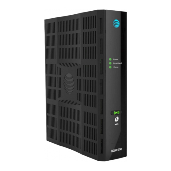
Page 17: Status Indicator Lights
LED Activity descriptions table to interpret the LED indicators. BGW210-700 Broadband Gateway Status Indicator Lights Front View 365-095-30882 Revision 4.0 BGW210-700 Broadband Gateway Release 1.0 Install and Operations Guide © 2016 ARRIS Enterprises LLC. All Rights Reserved. - Page 18 Green during Power On Self Test (POST), Power LED goes Solid Green and all other LEDs start functioning with normal behavior. If the BGW210-700 Broadband Gateway does not boot and fails its self- test or fails to perform initial load of the bootloader: ...
- Page 19 LEDs operate normally. 3. The BGW210-700 Broadband Gateway restarts automatically. As the BGW210-700 Broadband Gateway reboots, the LEDs display power-on behavior. 365-095-30882 Revision 4.0 BGW210-700 Broadband Gateway Release 1.0 Install and Operations Guide © 2016 ARRIS Enterprises LLC. All Rights Reserved.
- Page 20 Off = VoIP not in use (e.g. both VoIP lines are not configured) or BGW210-700 Broadband Gateway power is off. When in alert mode the Solid Green and Flashing Green will not be displayed and the LED will be off.
-
Page 21: Problem Isolation
Ethernet Solid Green = A 10/100/1000 Ethernet device is connected. 1,2,3,4 Off = The BGW210-700 Broadband Gateway is not powered or no (Rear Panel) powered devices are connected to the associated ports. Power Jack Green = The voltage present at the DC input connector is equal to or ... - Page 22 Disable any installed network devices (Ethernet, HomePNA, Wi-Fi) that are not being used to connect to the DSL gateway. 365-095-30882 Revision 4.0 BGW210-700 Broadband Gateway Release 1.0 Install and Operations Guide © 2016 ARRIS Enterprises LLC. All Rights Reserved.
-
Page 23: Rear Panel Connectors
Connectors on the rear panel are depicted below. BGW210-700 Broadband Gateway Rear Panel Note: The BGW210-700 Broadband Gateway supports two VoIP lines over one RJ14 (FXS) VoIP port. To connect two phone lines, an inner and outer pair splitter adapter must be attached to the RJ14 (FXS) VoIP port to terminate both lines. -
Page 24: Factory Reset Switch
Chapter 4: Basic Troubleshooting Factory Reset Switch The Reset switch will result in a reboot of the BGW210-700 Broadband Gateway. Depending on the software loaded on the BGW210-700 Broadband Gateway, holding it for an elongated duration of time may reset the device to factory defaults. -
Page 25: Technical Specifications And Safety Information
802.11 b/g/n and 802.11ac 400 mW high-power radio Wi-Fi Characteristics 2.4GHz support, 3x3 integrated omni-directional antenna with diversity 5GHz support, 4x4 365-095-30882 Revision 4.0 BGW210-700 Broadband Gateway Release 1.0 Install and Operations Guide © 2016 ARRIS Enterprises LLC. All Rights Reserved. -
Page 26: Power Supply
If collection systems are not available, contact ARRIS Customer Service for assistance at www.arris.com/consumers. 365-095-30882 Revision 4.0 BGW210-700 Broadband Gateway Release 1.0 Install and Operations Guide © 2016 ARRIS Enterprises LLC. All Rights Reserved. -
Page 27: Important Safety Instructions
Avoid using a telephone (other than a cordless type) during an electrical storm. There may be a remote risk of electric shock from lightning. 365-095-30882 Revision 4.0 BGW210-700 Broadband Gateway Release 1.0 Install and Operations Guide © 2016 ARRIS Enterprises LLC. All Rights Reserved. -
Page 28: Electrical Safety Advisory
United States: This device complies with 47 CFR Part 68 of the FCC Rules. Operation is subject to the following four conditions: 365-095-30882 Revision 4.0 BGW210-700 Broadband Gateway Release 1.0 Install and Operations Guide © 2016 ARRIS Enterprises LLC. All Rights Reserved. -
Page 29: Fcc Caution
This equipment should be installed and operated maintaining a minimum distance of 22 cm (9 inches) between the device and your body. 365-095-30882 Revision 4.0 BGW210-700 Broadband Gateway Release 1.0 Install and Operations Guide © 2016 ARRIS Enterprises LLC. All Rights Reserved. -
Page 30: Service Requirements
Changes or modifications to this product not authorized by the manufacturer could void your authority to operate the equipment. 365-095-30882 Revision 4.0 BGW210-700 Broadband Gateway Release 1.0 Install and Operations Guide © 2016 ARRIS Enterprises LLC. All Rights Reserved. -
Page 31: Arris Contacts
Chapter 7: ARRIS Contacts Chapter 7 ARRIS Contacts Technical Services For technical support on ARRIS products you can contact us by phone or on the web. By Telephone The Technical Assistance Center can be reached at: 1-888-944-HELP (4357) On the Web The Ask ARRIS web site gives you web access to service and support tools. - Page 32 Corporate Headquarters ARRIS · Suwanee · Georgia · 30024 · USA T: 1-678-473-2000 F: 1-678-473-8470 www.arris.com...
Need help?
Do you have a question about the BGW210-700 and is the answer not in the manual?
Questions and answers
Can I connect my usb printer to the router? If so, how?
Can the DSL broadband port in the BGW210 be used for a weather hub connection when also using the ethernet ports?