Table of Contents
Advertisement
Advertisement
Table of Contents

Related Manuals for Smith & Nephew JOURNEY II BCS


Summary of Contents for Smith & Nephew JOURNEY II BCS
- Page 1 Surgical Technique for use with the JOURNEY™ II BCS and JOURNEY™ II CR...
- Page 2 NAVIO™ Surgical System Surgical Technique for use with the JOURNEY™ II BCS and JOURNEY™ II CR Smith & Nephew 500081, Rev B Issue Date: 2016-11-16 The following technique is for informational and educational purposes only. It is not intended to serve as medical advice. It is the responsibility of treating physicians to determine and utilize the appropriate products and techniques according to their own clinical judgment for each of their patients.
- Page 3 Introduction This procedure guide provides an overview of the recommended surgical technique for using the NAVIO™ surgical system technology with the JOUR- NEY™ II CR (Cruciate Retaining) and JOURNEY™ II BCS (Bi-Cruciate Stabilized) Knee System. Smith & Nephew recommends that users review this guide prior to performing total knee arthroplasty utilizing the NAVIO system.
-
Page 4: Table Of Contents
Contents Intended Use, Indications, Contraindications..5 Design Rational/Surgical Planning Rational... 6 NAVIO Surgical System Overview ......7 Navio Instrument Trays .......... 8 Positioning the System .......... 9 1. System and Patient Setup ........10 2. Bone Tracking Hardware ........12 3. -
Page 5: Intended Use, Indications, Contraindications
Intended Use The NAVIO surgical system is intended to assist the surgeon in providing software-defined spatial boundaries for orientation and reference information to anatomical structures during orthopedic procedures. Indications for Use The NAVIO™ surgical system is indicated for use in surgical knee procedures, in which the use of stereotactic surgery may be appropriate, and where reference to rigid anatomical bony structures can be determined. -
Page 6: Design Rational/Surgical Planning Rational
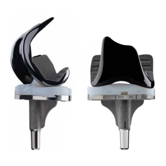
JOURNEY™ II TKA Total Knee Design Rationale The goal of the JOURNEY™ II Total Knee System is to enable a higher level of function for total knee replacement patients – to not only relieve pain, but to help them regain their active lifestyles (Figure 1). -
Page 7: Navio Surgical System Overview
NAVIO™ Surgical System Overview The NAVIO™ Surgical System is a surgical planning, navigation and intraoperative visualization system combined with a handheld smart instrument for bone sculpting. The optical tracking camera communicates the relative position of the handpiece (cutting tool), the femur, and the tibia (via rigid tracker arrays) to the computer cart, which runs algorithms that control the handpiece (Figure 2). -
Page 8: Navio Instrument Trays
NAVIO™ Instrument tray Small Parts Sterilization Case Femur Tracker Frame Handpiece Tracker Frame Handpiece The NAVIO Instrument tray consists of a two-level tray that contains the required instrumentation for a NAVIO-assisted surgery, including a robotic- controlled NAVIO handpiece, Anspach power drill, interchangeable guards, tracker frames, bone tracker hardware and clamps, a Z knee retractor, and a rasp that has flat and rounded rasping... -
Page 9: Positioning The System
Positioning the System Position the NAVIO™ computer cart so that the surgeon can clearly see and easily operate the graphical user interface at all times. The computer cart should be positioned on the opposite side of the leg to be operated. The camera stand should be placed approximately 1.5 m from the surgical site and 1.8 m - 2.1 m high, also on the opposite side of the leg to be operated. -
Page 10: System And Patient Setup
System and Patient Setup Preparing the System and Tool The surgical team will set-up the NAVIO™ system to utilize the integrated irrigation system (refer to the Irrigation Tubing Assembly section in the NAVIO™ Surgical System for Total Knee Arthroplasty User’s Manual), which will provide continuous irrigation throughout bone removal. - Page 11 System and Patient Setup Upon making the incision, carefully debride and inspect the joint. If any prominent spurs or osteophytes are present, especially in the area of the superior posterior femoral condyle, remove them with an osteotome or rongeur, as they could inhibit the leg motion.
-
Page 12: Bone Tracking Hardware
Bone Tracking Hardware Placing Tracking Hardware Rigid fixation of the femur and tibia tracking frames to the bone is critical for a successful NAVIO™- assisted surgery. The NAVIO system utilizes a two- pin bi-cortical fixation system. This fixation system is installed using bone screws, a tissue protector, and tracker clamps (2x) (Figure 7). - Page 13 Bone Tracking Hardware Slide the tracker clamp (with the clamp opening • oriented towards the camera) over the two bone screws until the bottom of the clamp is within 1 cm of the patient’s skin, taking care not to place the clamp where it is touching the patient's skin.
-
Page 14: Surgical Preferences
Surgical Preferences Workflow Preference The NAVIO™ Total Knee application allows the user to choose between a femur-first or a tibia- first workflow. This Cutting Workflow preference provides flexibility and the option to either prepare the tibia first, prior to collecting soft tissue balancing information, or to collect the soft tissue balancing information before any bone cuts are performed. - Page 15 Surgical Preferences Rotational References The NAVIO™ Total Knee application allows the user to choose landmark collection preferences on the femur and the tibia in order to define rotational references, from which the implant component placement plan and ligament balancing information is calculated.
- Page 16 Surgical Preferences Joint Line Selection Preference The joint line selection is an optional selection, which allows the user to choose a landmark point on the femur and/or tibia and offset a line perpendicular to the mechanical axis from that point to a chosen distance (Figure 15, 16). This reference line is then displayed during the implant planning stage, to guide the component placement.
-
Page 17: Registration
Registration CT-free Registration NAVIO’s™ CT-free registration process utilizes standard image-free principles in constructing a virtual representation of a patient’s anatomy and kinematics. The user may choose to move through the software’s workflow via the included NAVIO system footpedal or the touchscreen controls. - Page 18 Registration Ankle Center Using the point probe, input the locations of the medial and lateral malleoli points by identifying the most prominent portion (Figure 20). Ensure that the point probe is visible throughout the point collection. If the probe is not visible, check that the tracking spheres on the point probe array are not overlapping (in front, or behind) the tracking spheres on the tibia tracker array.
- Page 19 Registration Most Posterior Lateral Point • This point is used in conjunction with the anterior notch point and the most posterior medial point for initial sizing of the implant component. Figure 23. Anterior Notch Point • This point is used as a reference during prosthesis planning to prevent notching of the implant component.
- Page 20 Registration Femoral Condyle Rotational References Based on surgeon preference, there are three options on which the femur rotational reference frame can be defined . These rotational references are used during Implant Planning (Section 6) for component placement onto the patient anatomy. It is important to understand how these collections are taken on the patient’s bony anatomy so that they may be referenced properly during planning.
- Page 21 Registration Posterior Condylar Axis Collection • The femur posterior condyles selection for defining the femur rotational reference, uses the most medial and lateral posterior condyles collections, and allows the user to dial in the medial-lateral axis angle with respect to the two points collected. Figure 28.
- Page 22 Registration Medial Plateau Point • Take the singular low-point of cartilage wear on the medial side of the tibial plateau. Lateral Plateau Point • Attempt to access the lateral side of the tibial Figure 31. condyle by flexing the leg and internally rotating the tibia and manually distracting the joint.
- Page 23 Registration AP Axis Collection • While all of the other collections listed above are singular points referencing the tip of the point probe, this collection will reference the axis of the point probe. If the AP axis is selected for rotational reference collection, using the length of the pointer probe, collect the AP axis on the tibia, normal to the transepicondylar axis.
- Page 24 Registration Tibia Joint Line Reference [Optional- Based on Surgeon Preference] The tibia joint line reference allows the user to pick a landmark point on the bone surface and offset a line perpendicular to the mechanical axis from that point. Figure 37. Tibial Condyle Surface Mapping The Tibia Free Collection stage (Figure 38) offers a visualization of the tibial mechanical and rotational...
-
Page 25: Ligament Balancing
Ligament Balancing The Ligament Balancing stage (Figures 39a, 39b) consists of collecting ligament stress or laxity information in full extension and flexion. Joint Laxity Collection in Extension Technique Keeping the operative leg in full extension, apply constant and maximal stress to the contralateral ligaments, and collect varus and valgus data, maintaining knee flexion between -10 and +10 degrees. -
Page 26: Implant Planning
Implant Planning The Implant Planning stage presents to the user a virtual reconstruction of the patient’s femoral and tibial anatomy and visualizes soft-tissue ligament tension to aid in joint balance in extension and flexion of the patient knee. There are two visualization modes for implant placement, solid surface view (Figure 40a) and cross section view (Figure 40b). - Page 27 Implant Planning 1. Using the cross section mode, in the transverse and coronal view, confirm that the component size provides adequate coverage on the digitized femur bone surface (Figure 41). Drag vertically on this view screen to visualize the superior-most part of the implant component on the bone (Figure 42).
- Page 28 Implant Planning 5. The implant components for JOURNEY II knee system are posterior referenced. Therefore, in order to have greater resection on the posterior bone, and to increase posterior gap, the component may be downsized, without any change to the anterior transition of the component on to the bone.
- Page 29 Implant Planning 1. Confirm the implant size using the transverse viewscreen (bottom left) and the tibia size up/ down button arrows in the right-hand control panel on the right side of the screen underneath the Tibia Size button. 2. Confirm the posterior slope, utilizing the sagittal view (upper right), NAVIO software will display the posterior slope within this viewscreen, which reflects the slope of the tibial implant component...
- Page 30 Implant Planning Button Mapping Femur While the NAVIO™ System for Total Knee Arthroplasty User’s Manual details each button on this screen, the following five buttons (Figure 46) are particularly critical to understand. - The Checkpoint Verification button is used to manually force a check of the checkpoints in the femur and tibia.
- Page 31 Implant Planning Button Mapping Tibia While the NAVIO™ System for Total Knee Arthroplasty User’s Manual details each button on this screen, the following five buttons (Figure 47) are particularly critical to understand. - The Checkpoint Verification button is used to manually force a check of the safety checkpoints in the femur and tibia.
-
Page 32: Implant Planning - Soft Tissue Balancing
Implant Planning - Soft Tissue Balancing Step 2 of the Implant Planning section provides the user the ability to dial in soft-tissue laxity (gap/tightness) for the patient in extension and flexion. The soft-tissue gap planning is predicated on the stressed extension and flexion input from Ligament Balancing Input (Section 5). - Page 33 Implant Planning - Soft Tissue Balancing Gap Balancing The goal of this stage is to have balanced extension and flexion gaps, with no overlap in either condyle, (i.e, medial or lateral). The extension gap will likely look unbalanced when comparing the medial and lateral space if no ligament release has been performed for a deformed knee.
- Page 34 Implant Planning - Soft Tissue Balancing Ligament Balancing Manipulations SCENARIO MANIPULATION Balance is tight Move tibial component inferior and/or in extension reduce thickness and flexion Balance Move tibial component superior and/or is loose in increase poly thickness extension and flexion Balance is tight Move femoral component superior.
- Page 35 Implant Planning - Soft Tissue Balancing Ligament Balancing Manipulations SCENARIO MANIPULATION Balance is loose in the Internally rotate the femur implant to medial compartment in balance gap in the medial and lateral flexion compartments Balance is tight in the Externally rotate the femur implant medial compartment in to balance gap in medial and lateral flexion...
-
Page 36: Bone Cutting
Bone Cutting Bone Preparation For total knee replacement, NAVIO™ utilizes a hybrid approach for complete bone preparation, with the combined use of burs and saws. The NAVIO handpiece is used to create features on the surface of the patient bone that lock the cut guides in place, in accordance with the implant placement plan, for final bone preparation using recommended saws. - Page 37 Bone Cutting Cut Guide Placement Prior to preparation of the locking features for cut guides on to the patient bone surface using the NAVIO™ handpiece in speed control, the user is presented with a cut guide placement screen, where the goal is to size the appropriate cut guide for the operation.
- Page 38 Bone Cutting The user has the ability to move the cut guide anterior and posterior, as well as rotate it in the cut plane. Confirm that the cut slot portion of the guide is not impinging on the bone surface by referencing the cross section view, as well as the 3D view (See Figure 58).
- Page 39 Bone Cutting Screen Overview Figure 60 shows a typical cutting screen with the following icons/buttons called out: - Checkpoint Verification button, used to activate a confirmation of the safety checkpoints on femur and tibia. - Change Bur button, used when the user switches bur size to tell the system about the change.
- Page 40 Bone Cutting Bone Preparation Warning: The NAVIO™ system does not prohibit cutting of soft tissue, which may be in the surgical area. Always use retractors to protect ligaments and other capsular structures. Use steady movement to minimize potential for ligament damage. Warning: NAVIO control modes do not establish “no-cut”...
- Page 41 Bone Cutting Cut Femur The handpiece is used to prepare four cylindrical features in the patient’s bone in order to lock the NAVIO™ femur cut guide onto the bone surface. 1. Align the handpiece tool, under speed control on the cut zone (areas color-coded purple, blue and green on the monitor), by utilizing the cross-hair visualization, and the tool’s eye view.
- Page 42 Bone Cutting 10. Ensure that the dial on the block is set to the zero mark, and tighten the dial using the Smith & Nephew JOURNEY 3.5 mm hex driver. Using the recommended saw, prepare the five planar femur cuts, as recommended by the implant manufacturer in the JOURNEY II Total knee surgical technique.
- Page 43 Bone Cutting Using the handpiece, prepare four features in the patient’s bone in order to lock the NAVIO™ tibia cut guide onto the bone surface. Make sure to uncover the tibia tracker array if it was covered for protection while burring the femur. 1.
-
Page 44: Trial Reduction
Trial Reduction Trial Reduction - Confirm Sizing Trial Reduction After completing all of the bone cuts and adjustments to the final surfaces, the incision should be cleaned and dried thoroughly. Once bone surface preparation is complete, perform a trial reduction (Figure 68) with the appropriate size trial femoral component and trial tibial components as described in the JOURNEY™... -
Page 45: Cement And Close
Cement and Close Cement Final Components & Close Final Components For better anchoring of the cement, it is recommended to prepare additional anchor holes on both tibia and femur. The bone should be prepared before cementation with pulse lavage and then dried. Apply a thin layer of cement to the inner surfaces of the components. -
Page 46: Recovery Procedure Guidelines
In the following Recovery Action items, any reference to the JOURNEY™ II Total Knee Surgical Technique is referencing the document: Smith & Nephew JOURNEY™ II TKA Total Knee System Combined Technique for JOURNEY II BCS and JOURNEY II CR [PART NO: 00829 V1 11/13]. -
Page 47: Notes
Notes: ___________________________________________________________________________________ ___________________________________________________________________________________ ___________________________________________________________________________________ ___________________________________________________________________________________ ___________________________________________________________________________________ ___________________________________________________________________________________ ___________________________________________________________________________________ ___________________________________________________________________________________ ___________________________________________________________________________________ ___________________________________________________________________________________ ___________________________________________________________________________________ ___________________________________________________________________________________ ___________________________________________________________________________________ ___________________________________________________________________________________ ___________________________________________________________________________________ ___________________________________________________________________________________ ___________________________________________________________________________________ ___________________________________________________________________________________ ___________________________________________________________________________________ ___________________________________________________________________________________ ___________________________________________________________________________________ ___________________________________________________________________________________ ___________________________________________________________________________________ ___________________________________________________________________________________ ___________________________________________________________________________________ ________________________________________________________________________________... -
Page 48: Manufacturer Contact Information
Manufacturer: Blue Belt Technologies, Inc. 2905 Northwest Blvd, Ste. 40 Plymouth, MN 55441 USA Customer Support: tel) 763-452-4910 fax) 763-452-4980 email) CustomerSupport.Robotics@smith-nephew.com Blue Belt Technologies, Inc., now a company of Smith & Nephew. www.smith-nephew.com ™ Trademark of Smith & Nephew. All trademarks acknowledged.
Need help?
Do you have a question about the JOURNEY II BCS and is the answer not in the manual?
Questions and answers