ACU-RITE SENC 150 Reference Manual
Precision glass scale linear
Hide thumbs
Also See for SENC 150:
- Instructions manual (12 pages) ,
- Installation manual (8 pages) ,
- Manual (32 pages)
Table of Contents
Advertisement
Quick Links
Advertisement
Table of Contents

Related Manuals for ACU-RITE SENC 150


Summary of Contents for ACU-RITE SENC 150
- Page 1 SENC 150 REFERENCE MANUAL...
-
Page 3: Table Of Contents
SENC 150 Table of Contents / Warnings Page Introduction / Supplied items ........4 Preparing the mounting / Mounting information ... 5 Encoder dimensions ............. 8 Backup spar dimensions ..........10 Mounting the encoder without backup spar ....11 5.1 Mounting the encoder via end holes ......12 5.2 Mounting the encoder via center support .... -
Page 4: Introduction / Supplied Items
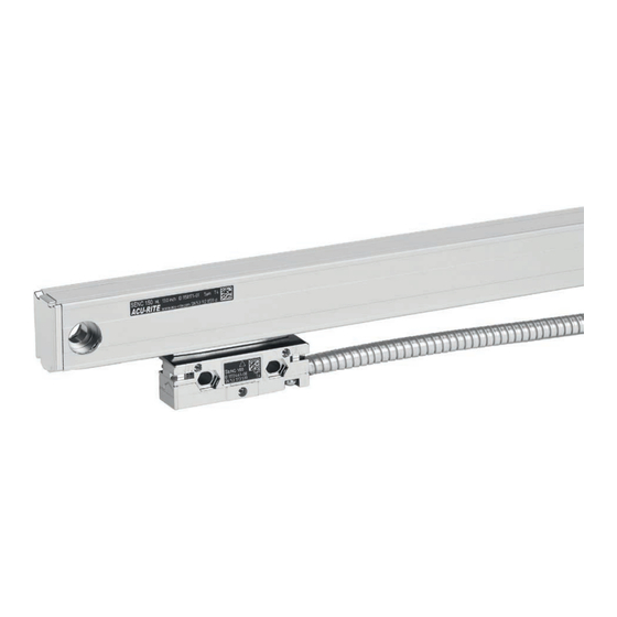
1 Introduction / Supplied items SENC 150 The SENC 150 precision glass scale linear encoder provides the Contents ML ≤ 1550 mm (60”) accuracy and reliability of an ACU-RITE measuring system with ® digital output. Features and options include: SENC 150 ... - Page 5 SENC 150 2 Preparing the mounting Mounting surface clean and free of paint. Protect sealing lips from splash water. Linear encoder F = Machine guideway ** Linear encoder with center support L = Length of backup spar (page 10)
-
Page 6: Preparing The Mounting / Mounting Information
2 Preparing the mounting / Mounting information SENC 150 Traverse path 11.75 mm (LL x 25.4 + 138.1)/2 mm 0.463” (LL + 5.437”)/2 Scale case Center marks ML/2 mm (LL + OT)/2 “ Alignment brackets (2x) Cable assembly Reading head assembly ML mm LL + OT “... -
Page 7: Mounting Information
SENC 150 2 Mounting information Mounting possibilities Determining cable direction Flush Offset Backup spar Determine cabel exit direction before mounting the encoder. mounting mounting mounting To change the cable exit direction, remove the cover plate and rotate it by 180°. -
Page 8: Encoder Dimensions
SENC 150 3 Encoder dimensions... - Page 9 SENC 150 3 Encoder dimensions = Measuring length [mm] = Measuring length [inch] = Overtravel 1.75” = Beginning of measuring length = required mating dimensions = for ML ≥ 625 mm to ≤ 1550 mm use mid-point fastening for ML ≥ 24” to ≤ 60” use mid-point fastening...
-
Page 10: Backup Spar Dimensions
4 Backup spar dimensions SENC 150 Encoder Encoder Encoder Encoder ML (mm) LL (inch) (mm) (inch) (mm) (inch) (mm) (inch) holes B ML (mm) LL (inch) (mm) (inch) (mm) (inch) (mm) (inch) holes B 185.50 7 .303 29.25 1.152 871.50 34.311... -
Page 11: Mounting The Encoder Without Backup Spar
SENC 150 5 Mounting the encoder without backup spar A variety of mounting conditions can be accomodated. Offset surfaces The machine configuration determines the brackets required to mount the linear encoder. Two typical mounting conditions are shown: flush and offset. -
Page 12: Mounting The Encoder Via End Holes
SENC 150 5.1 Mounting the encoder via end holes Bore hole pattern Mounting LL < 625 mm (24“): Use end mounting holes. P = Gauging point M6 x 25 mm (1/4”-20 x 1” BHCS) M6 flat washer M4 x 25 mm SHCS low head (8-32 x 5/8”... -
Page 13: Mounting The Encoder Via Center Support
SENC 150 5.2 Mounting the encoder via center support Bore hole pattern Mounting P = Gauging point 625 mm (24“) † LL M6 x 25 mm † 1550 mm (60”): (1/4”-20 x 1” BHCS) Use end mounting holes M6 flat washer with center support. -
Page 14: Mounting The Encoder With Backup Spar
SENC 150 6 Mounting the encoder with backup spar Mounting possibility Mounting Space of ≤4.5 mm (≤0.18”) use reading head leveling screws! Flush or offset mounting with a backup spar. Bracket used to reduce head to mounting surface gap. -
Page 15: Mounting The Reading Head
SENC 150 7 Mounting the reading head Mounting the reading head with hex nut Leveling screws M4 hex nut M3 x 12 mm SHSS M4 x 25 mm SHCS low head (8-32 x 5/8” SHCS low head) (8-32 x 3/4” SHCS low head) Adjust the leveling set screws as follows: ... -
Page 16: Checking The Mounting
SENC 150 8 Checking the mounting Connecting the encoder Route the cables with slack loops to allow for axis motion. Secure excess cable by fastening with clips or ties. Attach the linear encoder connectors to the readout. -
Page 17: Specifications
SENC 150 9 Specifications Mechanical specifications Digital Resolution 0.5 µm 1 µm 5 µm Grating pitch 20 µm Scale medium Light transmission reflective off of nickel coated glass Accuracy (@ 20° C) / 1000 mm ± 3µm, ± 5µm Max. traversing speed... -
Page 18: Pin-Outs
SENC 150 10 Pin-outs 11 Output signals Digital Differential Pin 1 Pin 2 Pin 3 Pin 4 Pin 5 Pin 6 Pin 7 Pin 8 Pin 9 green yellow blue white brown pink gray channel channel channel channel ground Vcc, +5.1... - Page 19 SENC 150...
- Page 20 ID: 516291-22 D516291-02-A-01 05/2017...
Need help?
Do you have a question about the SENC 150 and is the answer not in the manual?
Questions and answers