Table of Contents
Advertisement
Advertisement
Table of Contents

Related Manuals for Soundoff Signal pinnacle


Summary of Contents for Soundoff Signal pinnacle
- Page 1 OWNER’S MANUAL & INSTALLATION INSTRUCTIONS EPL9000 9.10...
-
Page 2: Table Of Contents
TABLE OF CONTENTS PAGE CONTENT TECHNICAL SPECIFICATIONS PRE-INSTALLATION PINNACLE BASICS FIXED HEIGHT BRACKETS AND HOOK MOUNTING FIXED HEIGHT BRACKETS PERMANENT MOUNTING 8-10 ADJUSTABLE HEIGHT BRACKETS AND HOOK MOUNTING 10-11 ELECTRICAL INSTALLATION 12-13 BREAKOUT BOX FLASH PATTERNS AND CONNECTOR INSTRUCTIONS CONTROLLER AND WIRE HARNESS INSTRUCTIONS... -
Page 3: Technical Specifications
Technical SPECIFICATIONS Input Voltage 10-16Vdc Current Draw (Amps) Average Peak Power Consumption (Watts) Inboard Module (ea): 0.5Amps @ 12.8Vdc 1.0Amps @ 12.8Vdc Corner Module (ea): 1.0Amps @ 12.8Vdc 2.0Amps @ 12.8Vdc 12.8 Takedown Module (ea): 0.5Amps @ 12.8Vdc 1.0Amps @ 12.8Vdc Alley Light Module (ea): 0.33Amps @ 12.8Vdc 0.65Amps @ 12.8Vdc Average = Flashing... -
Page 4: Pre-Installation
The lightbar is intended for use by authorized personnel only. It is the user’s responsibility to ensure they understand and operate the emergency warning devices in compliance with the applicable city, state and federal laws and regulations. (SoundOff Signal assumes no liability for any loss resulting from the use of this warning device.) -
Page 5: Pinnacle Basics
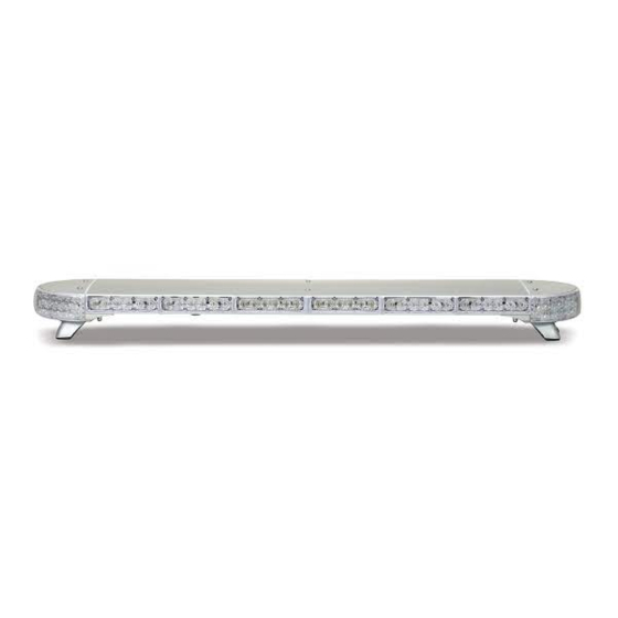
PINNACLE BASICS This is a basic configuration showing many of the features offered. Your PINNACLE may have a different configuration. This diagram should only be used as a reference. TOP VIEW WITH COVER ON 6 TOP COVER SCREWS TOP VIEW WITH COVER OFF... -
Page 6: Fixed Height Brackets And Hook Mounting
FIXED HEIGHT BRACKETS AND HOOK MOUNTING Mount fixed height brackets (See Figure 1) using supplied (3) T25 torx screws on each side. Temporarily place the lightbar in it’s correct position on the roof of the vehicle. The bar should be positioned about the center line of the “B” pillar. Based on the bar’s position, determine wire entry into vehicle. -
Page 7: Fixed Height Brackets Permanent Mounting
FIXED HEIGHT BRACKETS PERMANENT MOUNTING Locate the permanent hardware kit that is included. Kit will include (4) 1/4”-20 x 1“ hex head screws, (4) flat washers, (4) lock washers, (4) square nuts, and (6) T25 Torx Screws. Attach fixed height brackets to lightbar using T25 Torx Screws. Brackets should be adjusted to identical positions at both ends of lightbar. -
Page 8: Adjustable Height Brackets And Hook Mounting
ADJUSTABLE HEIGHT BRACKETS AND HOOK MOUNTING PIVOT HEIGHT & ROOF ANGLE ADJUSTMENT SCREWS FRONT TO BACK TILT ADJUSTMENT SCREWS VEHICLE SPECIFIC BRACKET VEHICLE SPECIFIC BRACKET ADJUSTMENT SCREW ADJUSTABLE RUBBER FEET HEIGHT ADJUSTMENT SCREWS Page 8... - Page 9 ADJUSTABLE HEIGHT BRACKETS AND HOOK MOUNTING Attach vehicle specific bracket to adjustable mounting bracket. 1 1/2” Allen drive screw must be placed “underneath” djustable mounting bracket (See Figure 1). Allen drive screw will be accessible through hole in front of adjustable bracket. Square nut must be placed in front of vehicle specific bracket.
-
Page 10: Electrical Installation
Featured Highlights: Mode Select: The PINNACLE Lightbar is equipped with 2 selectable pattern configuration modes via the Mode Select Input. Default is Mode 1 where the input is floating, Mode 2 is in use when the input activated. This feature allows 2 complete sets of patterns to be programmed into the Lightbar's non-volatile memory. - Page 11 ELECTRICAL INSTALLATION IMPORTANT: When passing cables through firewall or other sheet metal, insert grommet to protect the cable! Install a 40Amp Fuse (customer supplied) to the end of the RED wire of the Lightbar Power Cable. a. Remove the fuse before connecting any wires to the battery. b.
-
Page 12: Breakout Box
BREAKOUT BOX RED LIGHT No Inputs Flashes Every 5 Secs. Input Activated Steady On Added Input Brief Flash 40Amp FUSE (Customer Supplied) GREEN LIGHT Command Rec’d Steady On Has good (See below) connection GROUND LOW POWER (STANDBY) MODE POWER If there is no input to the breakout box for DRAIN WIRE CABLE 15 seconds, the lightbar will go into a... -
Page 13: Flash Patterns And Connector Instructions
FLASH PATTERNS AND CONNECTOR INSTRUCTIONS FLASH PATTERN TABLE BREAKOUT BOX HOOKUP: LED Takedown & Alley Flash Patterns RoadRunner™ Alternating 1.92 Make sure the 24-pin connector and the RJ-45 PowerPulse™ Alternating 3.00 connector are snapped in securely. Q-Switch™ Variable ETM™ Simultaneous 3.57 Follow the label for the wire color to connect to a 12Vdc source, which turns on that given light or... -
Page 14: Controller And Wire Harness Instructions
CONTROLLER AND WIRE HARNESS INSTRUCTIONS LIGHT MODULE WIRE HARNESS LOCATIONS REPLACEMENT OF INBOARD, CORNER, TAKEDOWN AND ALLEY LED MODULES: 1. Disconnect main power. 2. Remove top cover by removing 6 sealed torx head screws. 3. Locate module and remove mounting screw. Pull module from lightbar. 4. -
Page 15: Pinnacle Troubleshooting
PINNACLE TROUBLESHOOTING NORMAL OPERATION Under Normal operation with lightbar turned on the breakout box will have the Green and Red LED light on steady. When ever you change an input to the lightbar the Red LED on the breakout box will flash then go back to steady. -
Page 16: Replacement Parts
Alley Light Assembly Adjustable Height Bracket Hook Kit for ETL 5000 or Pinnacle Lightbars:* PETLM(nn) PETLR00 Permanent Mount Hardware for the Low Profile Fixed Height Bracket for use w/ ETL 5000 & Pinnacle Lightbars PEPL9GTT1C Pre-empt Module PEPL9RFGR2 Roof Grommet... -
Page 17: Product Maintenance
PRODUCT MAINTENANCE CLEANING - Keeping the lenses clean and scratch free will optimize the performance of the lightbar. To clean use a soft cotton cloth and mild soapy water to clean dirt and insects off from the lenses. Never use window cleaners or harsh chemicals on the lenses;... - Page 18 Fax number where RMA# should be faxed** SoundOff Signal will NOT accept returns without an RMA#. Each RMA# is good for only one (1) item and will expire (7) days after the date it was issued. Products must be shipped back to SoundOff Signal and the RMA# clearly marked on the outside of the package near the shipping label.
Need help?
Do you have a question about the pinnacle and is the answer not in the manual?
Questions and answers