
Related Manuals for Still R70-40T


Summary of Contents for Still R70-40T
- Page 1 Operating Instructions LPG forklift truck R70-40T R70-45T R70-50T 7081 7082 7083 Ident no. 171673 - EN...
-
Page 3: Table Of Contents
Table of contents Foreword Your industrial truck ........... 2 General . - Page 4 Table of contents Tyres ............. 25 Medical equipment .
- Page 5 Table of contents Operation Checks and operations prior to start-up ........54 Visual inspections .
- Page 6 Table of contents Hazard area ............104 Transporting pallets .
- Page 7 Table of contents Message SITZSCHALTER (SEAT SWITCH) ....... 145 AIR FILTER message ..........147 BREMSE ANZIEHEN (APPLY HANDBRAKE!) message .
- Page 8 Table of contents Maintenance data table ..........186 Safety instructions for maintenance .
- Page 9 Table of contents Attachment maintenance ..........221 500-hour maintenance/semi-annual maintenance .
- Page 10 Table of contents Technical data Dimensions ............248 VDI datasheet .
-
Page 11: Foreword
Foreword... -
Page 12: Your Industrial Truck
Foreword Your industrial truck Your industrial truck General The industrial trucks described in this user manual are built to the applicable standards and safety regulations. If your industrial truck is to be driven on public roads it must satisfy the applicable Road Traffic Act provisions for the country concerned. -
Page 13: Information About Documentation
Foreword Information about documentation Information about documentation Documentation scope • Operating and maintenance manual • Operating and maintenance manual for attachments (special equipment) • Maintenance data table • Spare parts list • VDMA rules for the proper use of industrial trucks •... -
Page 14: Issue Date And Currentness Of Manual
Issue date and currentness of man- May 2007 STILL is constantly engaged in the further de- velopment of industrial trucks. Please note that these operating instructions are subject to change and any claims based on the informa- tion and figures contained in these operating instructions cannot be asserted. -
Page 15: Explanations Of The Signal Terms Used
Foreword Information about documentation Explanations of the signal terms used: DANGER In the case of work procedures that must be strictly adhered to in order to prevent a danger to the life or physical condition of persons. WARNING In the case of procedures that must be strictly adhe- red to in order to prevent injury to persons. -
Page 16: Definition Of Directions
Foreword Information about documentation Definition of directions The directions forwards (1), backwards (3), right (2), left (4) give the installation locations of parts as seen from the driving position; the load is at the front. 6210_001-031 Sample graphics This documentation explains the (usually se- quential) sequence of certain functions or operations. -
Page 17: Environmental Considerations
Foreword Environmental considerations Environmental considerations Packaging During delivery of the industrial truck, cer- tain parts are packaged to provide protection during transport. This packaging must be re- moved completely prior to initial start-up. ENVIRONMENT NOTE The packaging material must be properly dis- posed of after delivery of the industrial truck. - Page 18 Foreword Environmental considerations 171673 [EN]...
-
Page 19: Introduction
Introduction... -
Page 20: Use Of Truck
Introduction Use of truck Use of truck Proper use The forklift truck described in this operating manual is suitable for lifting, transporting and stacking loads. The truck may only be used for its proper pur- pose, as set out and described in this operat- ing manual. -
Page 21: Place Of Use
Introduction Use of truck WARNING Risk of accident! Passengers are not allowed. The forklift truck may not be operated in areas where is a risk of fire, explosion or corrosion, or areas that are particularly dusty. Stacking or unstacking is not permissible on inclined surfaces or ramps. -
Page 22: Use Of Working Platforms
Introduction Use of truck Use of working platforms WARNING The use of working platforms is governed by natio- nal law. This law must be observed. This allowed only if the law allows the use of working platforms in your country. Consult your national authorities (in Germany the trade association) before any use. -
Page 23: Residual Risk
Introduction Residual risk Residual risk Residual dangers, residual risks Despite careful working and compliance with standards and regulations, the occurrence of other risks when using the industrial truck cannot be entirely excluded. The industrial truck and all other system com- ponents comply with current safety require- ments. -
Page 24: Special Risks When Using The Forklift Truck And Attachments
Introduction Residual risk • Loss of stability due to the load being unsta- ble or the load slipping etc. • Fire and explosion risks due to batteries and electrical voltages. • Human error - disregarding safety regula- tions. Special risks when using the forklift truck and attachments The manufacturer’s approval must be ob- tained for any unconventional use during... - Page 25 Introduction Residual risk 171673 [EN]...
-
Page 26: Overview Of Hazards And Countermeasures
Introduction Residual risk Overview of hazards and counter- measures NOTE This flat sheet is intended to help evaluate the hazards in your facility and applies to all drive types. NOTE Observe the national regulations for your country! Hazard Action Notes Check note √... - Page 27 Introduction Residual risk Hazard Action Check note Notes √ actioned - not affected Impermissible usage Issue of operating BetrSichVO (improper usage) instructions (Workplace Safety Ordinance) and ArbSchG (Health and Safety at Work Act) Written notice of BetrSichVO instruction to driver (Workplace Safety Ordinance) and ArbSchG (Health and...
-
Page 28: Risk For Employees
Introduction Residual risk Risk for employees According to the operating safety ordinance trucks so as to comply with the local provisions (BetrSichVO) and German Law on Health for usage. and Safety at Work (ArbSchG) the operator The result must be documented (Section 6 (see ⇒... -
Page 29: Safety
Safety... -
Page 30: Definition Of Terms Used For Responsible Persons
Safety Definition of terms used for responsible persons Definition of terms used for responsible persons Operating company The operating company is the natural or legal person that operates the industrial truck or in whose employment the industrial truck is used. The operating company must ensure that the industrial truck is used only for its proper purposes and in compliance with the safety in-... - Page 31 Safety Definition of terms used for responsible persons representative and have been specifically in- structed to drive the truck. Specific knowledge of the industrial truck to be operated is also required. The training requirements under §3 of the Health and Safety at Work Act and §9 of the plant safety regulations are satisfied if the driver has been trained in accordance with the BGG (General Employers’...
- Page 32 Safety Definition of terms used for responsible persons Prohibition on use by unauthorised per- sons The driver is responsible for the industrial truck during working hours. He may not allow unau- thorised persons to operate the truck. When leaving the truck, he must secure it against unauthorised use.
-
Page 33: Essentials For Safe Operation
Safety Essentials for safe operation Essentials for safe operation Insurance coverage on company premises In many cases, company premises are re- stricted public traffic areas. NOTE We advise checking your public liability insur- ance to determine whether you have insur- ance coverage for your industrial truck with respect to third parties in the event of damage in restricted public traffic areas. -
Page 34: Warning Regarding Non-Original Parts
Safety Essentials for safe operation For safety reasons, it is prohibited to drill holes in the driver’s overhead guard or to perform welding on it. In the case of welding to other locations of the forklift truck, the battery and all connections to the electronic control cards must be disconnected. -
Page 35: Tyres
Safety Essentials for safe operation Fixed set values may only be changed with the approval of the manufacturer. Work on the electrical system (e.g. connect- ing a radio, additional headlights etc.) is only permitted with the manufacturer’s written ap- proval. All electrical system interventions must be documented. -
Page 36: Safety Inspections
Safety Safety inspections Safety inspections Regular safety check of the industrial trucks Safety check based on time and extraor- dinary incidents jährliche Prüfung The operator (see ⇒ Chapter "Definition of gem. UVV terms used for responsible persons", P. 20) Mängel siehe Prüfbuch must make sure that the industrial truck is letzte Prüfung checked by a specialist at least once per year... -
Page 37: Regular Safety Check Of The Fuel Gas System
Safety Safety inspections Regular safety check of the fuel gas system Technical safety check of the fuel gas system In accordance with § 37 of the Trade Union Ordinance BGV D34 "accident prevention regulations for the use of liquid gas "(please observe your national regulations). -
Page 38: Insulation Testing
Safety Safety inspections (see ⇒ Chapter "Definition of terms used for responsible persons", P. 20) must ensure that the harmful substances in the exhaust are checked by a specialist at recurring and regular intervals, at least every six months, (see ⇒ Chapter "Definition of terms used for responsible persons", P. -
Page 39: Safety Regulations When Handling Consumables
Safety Safety regulations when handling consumables Safety regulations when handling consumables Permissible consumables WARNING Consumables can be dangerous. Follow the safety regulations when handling these substances. Refer to the maintenance data table for the permissible substances necessary for op- eration. (See ⇒ Chapter "Maintenance data table", P. -
Page 40: Lpg
Safety Safety regulations when handling consumables WARNING Prolonged intensive contact with the skin can result in loss of skin oils and irritate the skin! – Avoid contact and consumption. – Wear protective gloves. – After coming into contact with oil, wash the skin with soap and water, and then apply a skin care product. - Page 41 Safety Safety regulations when handling consumables The pressure of these gases in the container depends on the external temperature and may reach up to 25 bar or more. NOTE In these operating instructions, liquid gases are called LPG. DANGER Risk of explosion! LPG immediately becomes gaseous when it escapes;...
- Page 42 Safety Safety regulations when handling consumables Safe use of LPG trucks The LPG system must be checked for damage and leaks at least once per year by a special- ist in LPG systems, see ⇒ Chapter "Regular safety check of the fuel gas system", P. 3-27. The LPG system is subject to prescribed main- tenance intervals that must be maintained, see ⇒...
-
Page 43: Hydraulic Fluid
Safety Safety regulations when handling consumables NOTE Please also take into account the section ""General requirements for pressurised-gas vessels; Using pressurised-gas vessels"" in the technical regulations applicable to pressu- rised-gas vessels TRG 380 and 404, as well as national regulations where applicable. Electric hand lamps used in these rooms must be provided with an enclosed sealed cover and a strong basket guard. -
Page 44: Battery Acid
Safety Safety regulations when handling consumables WARNING These fluids are pressurised during operation of the forklift truck and are hazardous to your health. – Do not allow to come into contact with the skin. – Avoid inhaling spray. – Penetration of pressurised fluids into the skin is particularly dangerous if these fluids escape at high pressure due to leaks in... -
Page 45: Coolant
Safety Safety regulations when handling consumables WARNING Battery acid contains dissolved sulphuric acid. This is corrosive. – When working with battery acid, always wear protective clothing and eye protection. – Do not allow any acid to get onto the clothing or skin or into the eyes;... -
Page 46: Disposal Of Consumables
Safety Safety regulations when handling consumables Disposal of consumables ENVIRONMENT NOTE Materials that have to be disposed of following maintenance, repair, and cleaning must be systematically collected and disposed of in ac- cordance with regulations. Follow the national regulations for your country. Work may only be carried out in areas designated for the pur- pose. -
Page 47: Emissions
Safety Emissions Emissions Noise emissions The values were determined based on measurement procedures from the standard EN 12053 (noise measurement for industrial trucks based on EN 12001 and EN ISO 3744 and the requirements of EN ISO 4871). This machine emits the following sound-pressure levels: Continuous sound-pressure level in the driver’s compartment <... - Page 48 Safety Emissions or the operating elements in the truck are less than 2.5 m/s . There are therefore no mea- surement guidelines for these measurements. The personal vibration load on the driver over a working day shall be determined in accor- dance with the Directive 2002/44/EC by the operating company (see ⇒...
-
Page 49: Overviews
Overviews... -
Page 50: General View
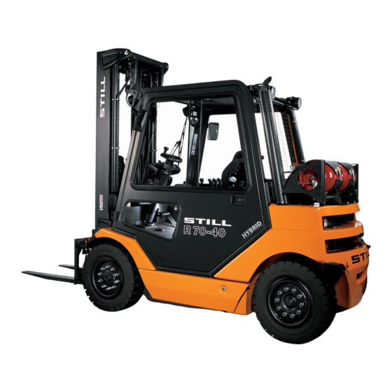
Overviews General view General view 7081_003-001 Lift mast Steering axle Overhead guard Drive axle Steering wheel Tilt cylinder Driver’s seat Fork arms 171673 [EN]... - Page 51 Overviews General view 171673 [EN]...
-
Page 52: Versions Of Driver's Compartment
Overviews Versions of driver’s compartment Versions of driver’s compartment Driver’s compartment, single pedal version 7081_003-010 171673 [EN]... - Page 53 Overviews Versions of driver’s compartment Steering wheel Storage box Steering column adjustment lever Bottle holder for 1 l PET bottles Direction of travel/flasher/fault multi-function Parking brake lever display Storage shelf for user and maintenance Travel direction switch manual (special equipment) "Lift-lower"...
-
Page 54: Driver's Compartment, Dual-Pedal Version
Overviews Versions of driver’s compartment Driver’s compartment, dual-pedal version 7081_003-039 171673 [EN]... - Page 55 Overviews Versions of driver’s compartment Steering wheel Storage box Steering column adjustment lever Bottle holder for 1 l-PET bottles Direction of travel/flasher/fault multi-function Parking brake lever display Storage compartment for operating and Alarm horn button maintenance manual "Lift-lower" operating lever Driver’s seat "Tilt"...
-
Page 56: Operating And Display Elements
Overviews Operating and display elements Operating and display elements Display and operating unit 1 0 0 % 2 3 6 0,4 h 12 : 15 7311_560-001 Front windscreen wiper switch Rear window heater switch Work light switch Rear searchlight display Rear windscreen wiper switch Rear searchlight switch Flashing light switch... -
Page 57: Direction Of Travel/Flasher/Fault Multi-Function Display
Overviews Operating and display elements Direction of travel/flasher/fault multi- function display The direction of travel/flasher/fault multi-func- tion display is used to display the direction of travel. In addition, the flasher is used to indi- cate that messages are shown on the display and operating unit. -
Page 58: Identification Points
Overviews Identification points Identification points Overview 10 bar STOP T E C H N O L O G Y STILL GmbH Hamburg jährliche Prüfung gem. UVV Mängel siehe Prüfbuch letzte Prüfung 20.. 20.. nächste Prüfung STOP STOP 7081_003-040 171673 [EN]... -
Page 59: Nameplate
Overviews Identification points Warning sign Decal information Decal information Accident prevention audit label Safe working load diagram Decal information Hook symbol Decal information Decal information Warning sign Decal information Safe working load diagram for attachment Label text (special equipment) Warning sign Decal information Warning sign Decal information (special equipment) -
Page 60: C. U. R. Data
Overviews Identification points C. U. R. data This label provides information on the weight and the load distribution of your truck. 7090-921-003 Admisssible rear axle load in kg Admissible total weight kg Admissible front axle load in kg Vehicle identification number xx xxxx x xxxxx NOTE Please state this serial number when making... -
Page 61: Accessories
Overviews Accessories Accessories Special equipment and variants Driver’s seat MSG 20 driver’s seat: • Imitation leather MSG 65 driver’s seat: • Textile cover, lumbar support • Imitation leather, lumbar support, heater, backrest extension • Textile cover, lumbar support, heater, back- rest extension MSG 75 driver’s seat: •... -
Page 62: Attachments
Overviews Accessories Attachments • Fork extension • Warning beam • Grille • Mandril • Crane arm • Snow remover • Shovel • Sideshift • Clamp forks without sideshift • Bale clamp without sideshift • Clamp forks with sideshift • Bale clamp with sideshift •... -
Page 63: Operation
Operation... -
Page 64: Checks And Operations Prior To Start-Up
Operation Checks and operations prior to start-up Checks and operations prior to start-up Visual inspections WARNING Damage or other defects of the forklift truck or at- tachment (special equipment) can result in acci- dents. If damage or other defects are identified on the forklift truck or attachment (special attachment) during the following inspections, do not use the vehicle until it has be repaired properly. -
Page 65: Opening The Bonnet
Operation Checks and operations prior to start-up – The roller tracks (2) must be lubricated with a visible lubricant film. – Check the hydraulic system and hydraulic oil tank where visible for damage and leaks. Damaged hoses must be replaced. –... -
Page 66: Checking The Engine Oil Level
Operation Checks and operations prior to start-up – Insert the release tool (3) and release the catch. To open it, use the release tool from the accessories. NOTE The catch can be secured with a lock. If ne- cessary, open the lock beforehand. –... -
Page 67: Filling The Washer System
Operation Checks and operations prior to start-up Filling the washer system – Open the sealing cap (1). – Fill the washer reservoir (2) with windscreen washer fluid. CAUTION If there is no anti-freeze in the system, the washer system (special equipment) may be damaged. –... -
Page 68: Opening Lpg Cylinders
Operation Checks and operations prior to start-up Opening LPG cylinders DANGER There is a risk of explosion if LPG escapes. – Do not smoke or use a naked flame / fire. – LPG cylinders should only be changed in well ventilated rooms and not near openings in the ground. -
Page 69: Opening The Lpg Tank Shut-Off Valve
Operation Checks and operations prior to start-up Opening the LPG tank shut-off valve DANGER There is a risk of explosion if LPG escapes! Do not smoke or use a naked flame/fire. – LPG tank shut-off valves (special equipment) should only be opened in well-ventilated rooms and not near openings in the floor. -
Page 70: Adjusting The Msg 65/Msg 75 Driver's Seat
Operation Checks and operations prior to start-up The fuel display (3) (special equipment) shows you how much LPG is available. 85 % 101.1 h 02 : 30 7311_003-040 Adjusting the MSG 65/MSG 75 driver’s seat DANGER Risk of accident! Do not adjust the seat whilst driving. –... - Page 71 Operation Checks and operations prior to start-up WARNING Risk of injury! To obtain optimum seat cushioning, you must ad- just the seat suspension to your own body weight. This helps your back and protects your health. To prevent injury, make sure that there are no ob- jects in the swivel area of the seat.
- Page 72 Operation Checks and operations prior to start-up Adjusting the seat suspension to your weight NOTE This adjustment should only be made while the seat is occupied. NOTE The MSG 75 seat is equipped with an elec- tric air suspension activated with an electric switch instead of a lever (3).
-
Page 73: Adjusting The Msg 20 Driver's Seat
Operation Checks and operations prior to start-up Adjusting the backrest extension (special equipment) – Adjust the backrest extension (6) by pulling it out or pushing it in to the desired position. To remove the backrest extension, move it past the end stop by jolting it upwards. 6321_003-040 Switching the seat heater (special equip- ment) on and off... - Page 74 Operation Checks and operations prior to start-up WARNING On some versions (special equip- ment), the amount of head clearance on your forklift truck may be restric- ted. On these versions, the distance between the head and the lower edge of the roofing sheet must be at least 40 mm.
-
Page 75: Adjusting The Steering Column
Operation Checks and operations prior to start-up Adjusting the seat suspension to your weight NOTE Make this adjust only whilst sitting in the seat. – Adjust your individual suspension comfort using the adjusting lever (1). 6321_003-044 Adjusting the steering column –... -
Page 76: Start-Up
Operation Start-up Start-up Turning on the key switch WARNING Before switching on the key switch, all tests before commissioning must be performed without detec- ting any defects. – First perform all tests before commissioning, see ⇒ Chapter "Checks and operations prior to start-up", P. - Page 77 Operation Start-up Upon switching on the key switch, the display shows the welcome screen in the set language until the truck controls have completely started Displays during the switching-on opera- tion • (2) Fuel level (special equipment) 100 % The fuel level can be displayed as either a percentage or bar display in the display field.
-
Page 78: Starting The Engine
Operation Start-up CAUTION Additional information can appear on the display. – If there are fault displays, please consult the instructions in the corresponding chapter, see ⇒ Chapter "Error messages", P. 138. Starting the engine – Apply the parking brake. WARNING Toxicity hazard from exhaust gases. -
Page 79: Operating The Signal Horn
Operation Start-up – If the message OELDRUCK (OIL PRES- in the display does not go out or SURE) reappears after starting the engine, switch off the engine immediately. – Refer to the information in the chapter en- titled Fault displays; see ⇒ Chapter "Error messages", P. -
Page 80: Restraining Belt
Operation Start-up – On trucks with two-pedal operation: press button (2). The signal horn sounds. 7081_003-045 Restraining belt DANGER Driving without a seat belt is dange- rous and never permitted! – Always fasten the belt before starting to drive. DANGER Only a fully enclosed cab with closed, fixed doors or bracket doors is an operator restraint system. - Page 81 Operation Start-up Fastening the restraining belt WARNING Risk of injury! – Always fasten the belt before moving the truck. Make sure that the belt is not twisted when faste- ning. – Use the belt only to secure a person! – If you notice any malfunction in the belt while fastening, do not put the truck into operation before the belt has been repaired.
- Page 82 Operation Start-up Fastening on a steep slope The automatic blocking mechanism prevents the belt from being extended whenever the forklift truck is on a steep gradient. It is not possible to pull the belt any further out of the retractor. –...
-
Page 83: Checking Function Of Brake System
Operation Start-up – Slowly guide the belt tongue (2) back to the retractor (3) by hand. NOTE Do not allow the belt to retract too quickly. The automatic blocking mechanism may be triggered if the belt tongue strikes the housing. It will then no longer be possible to pull the belt out again with the usual force. -
Page 84: Checking Function Of Steering System
Operation Start-up Checking the parking brake – Check operation of parking brake (2) at walking speed or on a large gradient. DANGER Risk of accident! During operation, the forklift truck must never be parked on slopes. In an emergency, secure the forklift truck by inserting chocks on the downhill side. -
Page 85: Setting The Traction Programs
Operation Start-up Setting the traction programs The driving and braking response of the drive can be set on the display and operating unit. – Press the traction programme key (1) un- til the number of the desired traction pro- 59 % gramme appears on the (2) display. -
Page 86: Driving
Operation Driving Driving Safety regulations when driving Driving conduct The driver must observe public road traffic reg- ulations when driving on company grounds. Driving speed must be appropriate to the local conditions. For example, the driver must drive slowly around corners, in tight passage ways, when driving through swing-doors, at blind spots or on uneven surfaces. - Page 87 Operation Driving WARNING In areas where use of mobile phones is prohibited, use of a mobile phones or radio telephones is ge- nerally not permitted. – Turn off the devices. Visibility when driving The driver must look in the direction of travel and have a sufficient view of the driving lane.
-
Page 88: Driveways
The required aisle widths (Ast) depend on the dimensions of the load. For pallets, these are: 7071_003-012 With pallet With pallet Aisle width (mm) 800x1200 1000x1200 lengthwise crosswise R70-40T 4418 4618 R70-45T 4470 4670 R70-50T 4510 4710 The forklift truck may only be used on drive-... - Page 89 Operation Driving to avoid the load from falling on the floor or the forklift truck being damaged. Condition of the driveways Driveways must be made sufficiently firm, level and free of dirt and fallen objects. Com- pensation must be made for drainage chan- nels, railway crossings and similar items;...
-
Page 90: Driving (Single-Pedal Operation With Multiple Lever Version)
Operation Driving Driving (single-pedal operation with multiple lever version) DANGER Risk of accident! – Operate the truck only from the driver’s seat. NOTE Please take note of the safety regulations while driving; see ⇒ Chapter "Safety regulati- ons when driving", P. 5-76. –... - Page 91 Operation Driving Travel direction switch – Using the direction switch (5), select the desired direction of travel. The appropriate arrow for the selected di- rection of travel lights up on the travel direc- tion/flasher/fault multi-function display (4). NOTE When the seat is vacated, the travel direction switch is set to neutral.
- Page 92 Operation Driving Reverse travel – Release the parking brake (6). – Toggle the direction switch (5) upward. The arrow for reverse travel (4) lights up. NOTE At the same time, an acoustic signal sounds (special equipment) as a warning or the back-up light and the front headlights light up (only if there is a lighting system (special equipment) in accordance with StVZO —...
- Page 93 Operation Driving Changing direction of travel NOTE You can also change the direction of travel whilst driving. Your foot can remain on the ac- celerator pedal. The truck is then braked and accelerated again in the opposite direction (reversing). – Take your foot off the accelerator pedal (3). –...
-
Page 94: Driving (Single-Pedal Operation With Version Including Mini-Console)
Operation Driving Driving (single-pedal operation with version including mini-console) DANGER Risk of accident! – Operate the truck only from the driver’s seat. NOTE Please take note of the safety regulations while driving, see ⇒ Chapter "Safety regulati- ons when driving", P. 5-76. –... - Page 95 Operation Driving Travel direction switch – Using the direction switch (5), select the desired direction of travel. The appropriate arrow for the selected di- rection of travel lights up on the travel direc- tion/flasher/fault multi-function display (4). NOTE When the seat is vacated, the travel direction switch is set to neutral.
- Page 96 Operation Driving Reverse travel – Release the parking brake (6). – Press the direction switch (5) backward. The arrow for reverse travel (4) lights up. NOTE At the same time, an acoustic signal sounds (special equipment) as a warning or the back-up light and the front headlights light up (only if there is a lighting system (special equipment) in accordance with StVZO —...
- Page 97 Operation Driving Changing direction of travel NOTE You can also change the direction of travel whilst driving. Your foot can remain on the ac- celerator pedal. The truck is then braked and accelerated again in the opposite direction (reversing). – Take your foot off the accelerator pedal (3). –...
-
Page 98: Driving (Two-Pedal Operation)
Operation Driving Driving (two-pedal operation) DANGER Risk of accident! – Operate the truck only from the driver’s seat. NOTE Please take note of the safety regulations while driving; see ⇒ Chapter "Safety regulati- ons when driving", P. 5-76. – Sit on the driver’s seat. The driver’s seat is equipped with a seat switch. - Page 99 Operation Driving Forwards travel – Release the parking brake (6). – Depress the accelerator pedal (3). The arrow for forward travel (4) lights up. The forklift truck moves forwards. The speed is controlled by the accelerator pedal position. When releasing the accelerator pedal, the forklift truck decelerates.
- Page 100 Operation Driving position. When releasing the accelerator pedal, the forklift truck decelerates. On a gra- dient the truck creeps downhill slowly after a stop. DANGER Risk of accident! Trucks with zero braking (special equipment) do not have an electrical braking func- tion! –...
-
Page 101: Service Brake
Operation Driving Service brake DANGER Risk of accident! Always choose a driving speed that will provide a sufficient stopping distance. Note that the pure braking distance increases at the square of the speed, and that sharp braking can cause the drive wheels to skid and the truck to tip over. - Page 102 Operation Driving Operating the service brake – Slow the truck by taking your foot off the accelerator pedal (2). – If the resultant braking action is not suffi- cient, use the footbrake (1) as well. In the first section of the pedal’s travel, only the electric brake takes effect;...
-
Page 103: Operating The Parking Brake
Operation Driving Operating the parking brake – To park the vehicle, pull the parking brake lever (2) up and let it engage. WARNING Risk of accident! If the parking brake is not applied, the truck can roll away. It can no longer be driven. The travel direc- tion/flasher/message multi-function display (3) goes out. -
Page 104: Steering
Operation Driving Steering – Steer the vehicle by turning the steering wheel (1) accordingly. For turning radius information, see ⇒ Chap- ter "Technical data", P. 247. WARNING Risk of accident! If the hydraulics fail, steering is tight (emergency steering property). 7071_003-015 171673 [EN]... -
Page 105: Lifting
Operation Lifting Lifting Lifting system variants Lifting operations are largely dependent on the following factors: • The mast with which your truck is equipped. See ⇒ Chapter "Lift mast versions", P. 5-95. • The lifting system with which your truck is equipped. -
Page 106: Malfunction During A Lifting Operation
Operation Lifting Triplex mast (special equipment) When the "lift-lower" operating lever is moved backwards, the inner cylinder moves up to (3)free lift, and then the outer cylinders directly raise the inner mast up to the max. (2)height. NOTE When raising above the free lift, the fork carri- age always remains at the upper edge of the extending mast tip. - Page 107 Operation Lifting – Notify the service centre. Load chains not under tension DANGER There is a danger that the load could suddenly fall. – Make sure that the chain(s) does (do) not be- come slack when lowering the load. Slack chains can, for instance, result from: •...
-
Page 108: Controls, Lifting System
Operation Lifting Controls, lifting system Operation of the lifting system depends on which controls the forklift truck is equipped with. Possible equipment variations are as follows: • Multi-lever controls (1) and (2). – The following information must be observed regardless of the equipment variation: DANGER Risk of accident! The lifting system must only be operated when the... -
Page 109: Lifting System, Multi-Lever Operation
Operation Lifting Lifting system, multi-lever operation Tilt mast To tilt mast forward: – Push "Tilt"(2) operating lever forward. To tilt mast backwards: – Pull back "Tilt" operating lever (2). Lift, lower fork carriage To raise fork carriage: – Pull back the "Lift-Lower" operating lever (1). -
Page 110: Fork Extension
Operation Lifting Fork extension – Slide the fork extension (1) (special equip- ment) onto the fork arms and secure it with the socket pins (2). WARNING The fork extension affects the stability of the forklift truck. The weights allowed according to the capacity ra- ting plate must thus be reduced in relation to the actual load distance;... - Page 111 Operation Lifting Reverse operation 7090_862-014 CAUTION Loads cannot be lifted up on the fork arms due to the missing(1)load support. When driving, the centre of gravity of the load may not be(2)higher than 600 mm above the ground. The fork extension (special equipment) may not be used.
-
Page 112: Working With Loads
Operation Working with loads Working with loads Safety regulations when handling loads The safety regulations for handling loads are shown in the following sections. DANGER Risk to life! The operating hydraulics may only be operated from the driver’s compartment. Never walk or stand underneath suspended loads or raised fork arms. -
Page 113: Prior To Taking Up A Load
Operation Working with loads Prior to taking up a load Load capacity The load capacity specified for the forklift truck may not be exceeded. It is affected by the load centre of gravity and the lift height and possi- bly the tyres. Observe the capacity plate to the right of the driver’s compartment. -
Page 114: Carrying Loading Units
Operation Working with loads Carrying loading units To ensure secure supporting of the load, it must be ensured that the fork arms are suffi- ciently far apart and are positioned as far as possible under the load. If possible, the load should rest on the back of the fork. -
Page 115: Transporting Pallets
Operation Working with loads WARNING Risk of injury The forks must not be stepped on. WARNING Risk of injury Do not step under the raised forks. WARNING People can be injured in the hazard area of the forklift truck. No persons should be in the hazard area of the forklift truck, except the driver in his normal ope- rating position. -
Page 116: Transport Of Swinging Loads
Operation Working with loads Transport of swinging loads Contact your national regulatory authorities (trade associations in Germany) prior to trans- porting swinging loads. National regulations may place restrictions on these operations. Please contact the authority responsible. DANGER Swinging loads can result in the following risks: •... -
Page 117: Taking Up Loads
Operation Working with loads DANGER Risk of accident! When transporting hanging loads, never abruptly perform or end driving and load movements during transport. Never drive on slopes with a hanging load! Containers with fluids cannot be transported as hanging loads. Taking up loads –... - Page 118 Operation Working with loads – Position the fork arms. – Place the mast in a vertical position. – Raise the fork carriage to the stack height. DANGER Risk of accident! – When the mast is tilted forward, make sure that the forklift truck does not tilt forward and that the load does not slip.
- Page 119 Operation Working with loads – Back out. CAUTION Risk of component damage! – Watch behind you for a clear pathway. – Drive backward carefully and slowly until the load has cleared the racking. Apply the brakes gradually. 7090_800-007 – Tilt the mast back. 7090_800-008 171673 [EN]...
-
Page 120: Transporting Loads
Operation Working with loads – Lower the load and maintain appropriate ground clearance. Now you can drive away. 7090_800-009 Transporting loads WARNING Risk of accident! As the height at which a load is transported increases, the stability decreases. – Always drive with the load lowered. –... - Page 121 Operation Working with loads – Only drive with the mast tilted back. 7090_800-011 – Drive slowly and carefully around sharp corners! – Always accelerate and brake gradually! DANGER Risk of accident! Do not start quickly, do not apply brake fully! 7090_800-012 171673 [EN]...
- Page 122 Operation Working with loads – Never drive with a laterally protruding load! (e.g. with a sideshift or sideshift device)! 7090_800-013 171673 [EN]...
-
Page 123: Depositing And Retrieving Loading Units
Operation Working with loads Depositing and retrieving loading units – Drive up to the stack with the load lowered in accordance with operating instructions. – Place the lift mast in a vertical position. WARNING Risk of accident! If your forklift truck is equipped with greater forward tilt (special equipment) (over 3°), the load can slip or the forklift truck can tip over. -
Page 124: Driving On Ascending And Descending Slopes
Operation Working with loads Driving on ascending and descend- ing slopes DANGER Risk to life! On ascending and descending slopes the load must be carried facing uphill. Only those ascending and descending slopes which are marked as traffic routes may be used and can safely be used in accordance with the technical data for this forklift truck, see ⇒... -
Page 125: Driving On Loading Bridges
Operation Working with loads approx. R70-40T 10,500 kg approx. 11,500 R70-45T approx. R70-50T 12,100 kg Driving on loading bridges 7090_001-009 DANGER Risk of accident! – Before driving across a loading bridge, ensure that it is properly attached and secured and has adequate load-bearing capacity (lorry, bridge). -
Page 126: Working With Attachments
Operation Working with attachments Working with attachments Assembling attachments If attachments are assembled at the place of use, the specifications in the operating instruc- tions for the attachment must be followed. Prior to being put into service for the first time, proper operation of the attachment and visibil- ity from the driver’s position with and without a load must be checked by a specialist (see... -
Page 127: Depressurising Connections For Attachments
Operation Working with attachments attachment. After each assembly, the attach- ment must be checked for proper functioning prior to being put into operation for the first time. Lifting capacity with attachment The permissible lifting capacity of the attach- ment and the allowable load (lifting capacity and load moment) of the forklift truck may not be exceeded in the combination of attachment and payload. -
Page 128: General Information On Control Of Attachments
Operation Working with attachments Depressurising, multi-lever controls – Lower fork carriage to the ground, tilt mast as far back as possible. – Switch off the key switch. – Operate all hydraulic operating levers (ar- rows) multiple times up to their end posi- tions. -
Page 129: Controlling Attachments Using Multi-Lever Controls
Operation Working with attachments Controlling attachments using multi- lever controls The attachments (special equipment) are controlled in this version using the operating levers (1). The pictograms on the operating levers al- ways show the function that is activated by that lever. The meanings are as follows: –... -
Page 130: Operating Attachments Using Multi-Lever Controls And The 5Th Function
Operation Working with attachments Operating attachments using multi- lever controls and the 5th function NOTE The designation "5th function" refers to the four functions that can be controlled using the four operating levers and that the func- tion which can be controlled using the func- tion change-over switch then constitutes the "5th function". -
Page 131: Taking Up A Load Using Attachments
Operation Working with attachments – Please note symbols 3 to 11! Reach frame or forks forwards/back- wards Sideshift moves to the left/to the right. Adjust fork arms: open/close Release/clamp load retainer Raise/lower load Turn to the left/to the right Tip shovel over/tip shovel back Tilt lift mast or forks to the left/to the right 7071_003-106... -
Page 132: Operation Of Additional Equipment
Operation Operation of additional equipment Operation of additional equipment Switching lighting on and off (special equipment) – Press the switch (1) for the work lights. The work lights are (3) switched on. 59 % – Press the light switch (2). The parking lights (4) are switched on. -
Page 133: Switching Flashing Light Off And On
Operation Operation of additional equipment Switching flashing light off and on – Press the switch (1) for the flashing light. The flashing light (2) is switched on. NOTE 100 % Pressing the switch again switches the flas- 2 3 6 0,4 h hing light back off. -
Page 134: Switching Hazard Warning System Off And On (Special Equipment)
Operation Operation of additional equipment Switching hazard warning system off and on (special equipment) – Press (1) warning light switch. All flashing lights (3) and the two direc- tion indicator lights (2) in the direction of 100 % travel/flasher/fault multi-function display flash. 2 3 6 0,4 h NOTE Pressing the switch again switches the hazard... -
Page 135: Switching Direction Indicators Off And On
Operation Operation of additional equipment Switching direction indicators off and – Activate the right or left direction indicators as required by moving the direction indica- tor switch (1) to the left or right. The direction indicators (2) or (3) light up. NOTE To reset, move the switch half the actuation distance in the opposite direction. -
Page 136: Cab
Operation Operation of additional equipment Opening the cab doors DANGER Risk of accident! – Always keep the doors closed when driving. DANGER Only a fully enclosed cab with closed, fixed doors or bracket doors is an operator restraint system. PVC doors are not a restraint system. -
Page 137: Heater
Operation Operation of additional equipment Heater Switch on blower and heater (special equipment) DANGER Risk of explosion! The heater should not be operated near storage rooms or similar facilities where fuel vapours or coal, wood or grain dust could be accumulate. - Page 138 Operation Operation of additional equipment Switching on cruise control WARNING Risk of accident! When using cruise control, the special behaviour of this function and the dangers associated with it must be observed by the driver, in addition to the safety guidelines. –...
- Page 139 Operation Operation of additional equipment Switching off cruise control There are different ways of switching off the cruise control function. If the cruise control function is switched off, the forward travel direction display will light up again(2)continuously. The cruise control function can be switched off by operating •...
-
Page 140: Trailer Operation
Operation Trailer operation Trailer operation Towed load NOTE This forklift truck is suitable for the occasional towing of trailers and is equipped with a towing device for this purpose. This occasional to- wing may not exceed 2% of the daily operating time. -
Page 141: Coupling The Trailer
Operation Trailer operation CAUTION The maximum permissible speed when towing is 5 km/h. Do not exceed the maximum permissible speed. Do not couple the forklift truck in front of rail vehic- les. Pushing of carriages of any type is prohibited. WARNING Towing changes the vehicle handling characteris- tics! - Page 142 Operation Trailer operation – Place the wheel chock in position (2) (spe- cial equipment), see ⇒ Chapter "Parking the truck securely", P. 5-171). 7071_003-107 – Press the towing pin (3) down, turn it 90° and pull it out. – Insert drawbar into the recess in the coun- terweight.
-
Page 143: Towing Trailers
Operation Trailer operation Towing trailers 7090_900-011 – Before you tow a trailer for the first time, practice driving in a suitable area. – When driving through a narrow section of aisle, take the dimensions of the trailer and load into consideration. –... -
Page 144: Operation Of Indicator And Operating Unit
Operation Operation of indicator and operating unit Operation of indicator and operating unit Displays Normal displays The following displays are normally visible (factory setting): • (1) Fuel level (special equipment). 85 % • (2) Set traction program with the numbers 1 to 5. -
Page 145: Setting And Changing The Displays
Operation Operation of indicator and operating unit Setting and changing the displays To set or change the displays, you must first switch to the "KONFIGURATION (CONFIGU- RATION)" menu: – Place the key switch in position "I". KONFIGURATION – Simultaneously press the traction program SPRACHE key (1) and the menu selection key (2) to switch to the "PASSWORD"... -
Page 146: Resetting The Daily Kilometres And Daily Operating Hours
Operation Operation of indicator and operating unit – Leave the menu and advance to the next higher level by pressing the arrow key (4). NOTE The date is set in a similar manner. Resetting the daily kilometres and daily operating hours The daily kilometres and daily operating hours displays can be reset to zero: –... -
Page 147: Fleet Manager Functions
Operation Operation of indicator and operating unit Fleet Manager functions Fleet Manager functions (special equipment) can be executed using the smart card (1). Ask your service centre. 59 % 2 3 6 0,4 h 12 : 15 6210_924-001 Accident recorder (special equipment) The accident recorder is an auxiliary device to the Fleet Manager. -
Page 148: Error Messages
Operation Error messages Error messages Diagram If a malfunction or a message is displayed on the display and control(1)unit, the display lights up on the combination display for direc- tion of travel/flasher/message. 7071_003-034 The following malfunction indications and messages can appear on the display:(2)A gra- phic symbol and a message describing(3)the faulty function and an error code consisting of(4)a letter and a 4-digit number. -
Page 149: Fault Code Table
Operation Error messages Fault code table The table provides you with an overview of the possible displays. The "Comment" column contains information about the procedure to follow when the corresponding messages are displayed. Message text (German) / Display animation Comment Error code Cyclic display every Traction motor(s) is/are too hot. - Page 150 SITZSCHALTER 30 sec hours. (SEAT SWITCH) A3027 Truck may still be running at reduced speed and with reduced lifting capacity. Briefly stand up and sit down again. If this does not resolve the problem, contact the service centre. Cyclic display every...
- Page 151 Operation Error messages Display animation Message text (German) / Comment Error code Cyclic display every Short circuit in sensor power supply. Vehicle POWER SUPPLY A2242 30 sec cannot be driven. A2257 Contact your service centre. Cyclic display every Traction drive not functioning. UEBERWACHUNG 30 sec Release the accelerator pedal.
-
Page 152: Safety Belt Message
Operation Error messages Display animation Message text (German) / Comment Error code Cyclic display every Starter battery does not charge. ALTERNATOR A5811 30 sec Contact your service centre. Cyclic display every Traction motor or generator overheated. MOT/GEN-TEMP A5034 30 sec Allow to cool. - Page 153 Operation Error messages Seat belt not worn, driver’s seat occu- pied. SICHERHEITSGURT – Switch on key switch. The message appears in the SAFETY BELT display as long as you operate an operating lever, the steering wheel, or the accelerator pedal. The forklift truck drives slowly or does not drive at all;...
- Page 154 Operation Error messages – Remove the seat belt from the buckle, fit the belt in line with the instructions and fasten it again. The forklift truck can again be operated with- out restriction. The seat belt is unfastened while driving –...
-
Page 155: Message Sitzschalter (Seat Switch)
Operation Error messages Message SITZSCHALTER (SEAT SWITCH) NOTE The truck is equipped with a seat switch. If the message SITZSCHALTER (SEAT SWITCH) appears on the display, the truck will only move slowly or (optionally) not at all. Depending on the selected version, the ope- rating hydraulic functions (lift/tilt) are either available as normal, slowed down or not avai- lable at all. - Page 156 Operation Error messages Exceeding the shift time NOTE SITZSCHALTER The shift time is adjustable. When the key switch is switched on after sit- ting steadily for the set time, the message appears SITZSCHALTER (SEAT SWITCH) on the display. This also occurs when an operating lever or the accelerator pedal is op- erated.
-
Page 157: Air Filter Message
Operation Error messages AIR FILTER message If the message appears on the AIR FILTER indicator and operating unit, the air filter insert must be replaced, see ⇒ Chapter "Changing the air filter insert", P. 6-202. LUFTFILTER 7311_003-005 BREMSE ANZIEHEN (APPLY HANDBRAKE!) message DANGER Risk of accident! -
Page 158: Gabeln Absenken (Lower Forks) Message
Operation Error messages The truck moves slowly despite the park- ing brake being applied BREMSE ANZIEHEN If you park the forklift truck without applying the parking brake sufficiently securely, the fork- lift truck will slowly roll away. The message BREMSE ANZIEHEN (APPLY HANDB- appears in the display. -
Page 159: Reference Lift Message
Operation Error messages REFERENCE LIFT message NOTE REFERENZHUB If you have shut down the control unit and lower the load with the lift-lower operating lever, the following happens when you restart: You switch on the key switch. In the display, the message (special REFERENCE CYCLE... -
Page 160: Bremsgeber (Brake Sensor) Message
Operation Error messages BREMSGEBER (BRAKE SENSOR) message If the BREMSGEBER (BRAKE SENSOR) message appears, the maximum driving speed is reduced. The brake sensor in the brake pedal must be checked. – Contact your service centre. BREMSGEBER 7071_003-085 SURVEILLANCE message If the UEBERWACHUNG (SURVEILLANCE) message appears, a fault has occurred in the process monitoring. -
Page 161: Mot/Gen-Temp (Mot/Gen Temp) Message
Operation Error messages MOT/GEN-TEMP (MOT/GEN TEMP) message If the MOT/GEN-TEMP (MOT/GEN TEMP) message appears, the traction motor or the generator is overheated, or a cable is broken. – Stop working and allow the truck to cool. However, do not turn off the key switch. MOT/GEN-TEMP NOTE If usability is impaired, please contact your... -
Page 162: Oeldruck (Oil Pressure) Message
Operation Error messages OELDRUCK (OIL PRESSURE) message CAUTION Risk of engine damage! If the message OELDRUCK (OIL PRESSURE) appears, the oil pressure in the engine is too low. OELDRUCK – Stop the engine immediately. The message can have different causes: •... -
Page 163: Kuehlmitteltemp (Coolant Temp.) Message
Operation Error messages KUEHLMITTELTEMP (COOLANT TEMP.) message If the KUEHLMITTELTEMP (COOLANT message appears, the coolant tem- TEMP.) perature is too high. The message can have different causes: • Insufficient coolant in the cooling system. KUEHLMITTELTEMP Check the coolant level; see ⇒ Chap- ter "Topping up coolant and checking coolant concentration", P. -
Page 164: Operation In Special Operating Situations
Operation Operation in special operating situations Operation in special operating situations Transport When driving the truck onto the means of transport, pay attention to the following: • The load/lifting capacity of the means of transport, ramps and loading bridges must be greater than the loading weight of the truck. - Page 165 Operation Operation in special operating situations Lashing – Attach the cable (1) to both sides of the truck and then secure the cable at the rear. 7071_003-126 – Attach the cable (1) to the towing pin (2) and secure the truck at the front. 7071_003-127 171673 [EN]...
-
Page 166: Towing
Operation Operation in special operating situations Towing If the brake for the towed forklift truck is no longer functional, the forklift truck can only be towed with a fixed connection (towing bar). To tow the forklift, a towing vehicle with suffi- cient tractive power and braking force for the unbraked towed load is required. - Page 167 Operation Operation in special operating situations Determining the loading weight – Park the truck so it is secured; see ⇒ Chap- ter "Parking the truck securely", P. 5-171. – Determine the loading weight of the truck. – Read the following weights on the factory nameplate, and if necessary, the factory nameplate of the attachment, and perform the addition:...
- Page 168 Operation Operation in special operating situations – Loop the lifting straps to the right and the left around the main traverse (1) on the outer mast of the lift mast. 7071_003-065 – Loop the lifting straps (2) around the coun- terweight between the counterweight and the steering axle.
-
Page 169: Frequent Short-Term Operation
– If the engine died on its own while the gas shut-off valve was still open, start the engine with closed shut-off valve until it starts up. Afterwards, ope- rate at increased idling speed until it repeatedly stalls. -
Page 170: Jump Starting
Under no circumstances should the engine be shut off via the ignition when the evaporator is iced up, since very cold residual gas still in the evaporator chamber could thermally expand as it warms to the ambient temperature, leading to impermissible excess pressure in the evaporator chamber. - Page 171 Operation Operation in special operating situations – Start the engine, see ⇒ Chapter "Starting the engine", P. 5-68. – Once the engine is running, remove the jumper cables in exactly the reverse order. – Replace the floorplate. – Close the bonnet. 171673 [EN]...
-
Page 172: Behaviour In Emergencies
Operation Behaviour in emergencies Behaviour in emergencies Procedure if truck tips over WARNING Risk of injury! Failure to comply with the limits specified in these operating instructions, e.g. driving on unacceptably steep inclines or failing to adjust speed when cor- nering, can cause the truck to tip over. -
Page 173: Emergency Lowering
Operation Behaviour in emergencies Emergency lowering NOTE If the load cannot be lowered from a raised position due to a control failure, emergency lowering is possible. DANGER Risk to life! Do not walk underneath the raised load! NOTE A 4-mm angle screwdriver is located on the 7071_003-092 right-hand side of the valve block frame for use when performing the following work (1). -
Page 174: Disconnecting The Battery
Operation Behaviour in emergencies Disconnecting the battery In order to quickly disconnect the battery in the event of a dangerous situation (e.g. a burning cable or electrical malfunction), the negative battery terminal is provided with a quick-dis- connect battery-terminal clip. NOTE The battery is located on the left side, under- neath the floorplate. -
Page 175: Refuelling
Operation Refuelling Refuelling Changing the LPG cylinder DANGER There is a risk of explosion if LPG escapes. – Check that LPG cylinders have approval. LPG cylinders with an expired inspection date should not be used. The inspection intervals laid down in the regulation applicable to pressure vessels must be observed without fail. - Page 176 The connecting nuts on cylinders should only be released slowly and only very little at first, as the gas still in the line will squirt out. Pipework and its accessories for gas in the liquid phase and LPG containers must not be exposed to an impermissible level of heat.
- Page 177 Operation Refuelling – On the protective cover (1) pull the release pin (2) and flip open the protective cover. 7081_003-003 – Close the cylinder valve (3). – Securely grip the connection nipple with the handhold (5) and carefully release the union nut (4) (left-hand thread).
-
Page 178: Filling The Lpg Tank
Operation Refuelling – Swing the handle of the tensioning device (6) upwards and remove the hook (8) from the mounting support. – Remove the top of the cylinder holder (7). – Exchange the empty gas cylinder for a full one. NOTE When installing the gas cylinder, make sure that the connection screw joint of the cylinder... - Page 179 NOTE We recommend that you refuel before starting work if the machine is still cold. If there is a major difference in temperature between the storage tank out in the open and the tank on the truck, the delivery pressure of the pump may no longer be sufficient for proper filling.
- Page 180 Operation Refuelling WARNING LPG can cause frostbite on the skin! – Accordingly, always wear protec- tive gloves. – Close the shut-off valve (3). – Unscrew the locking cap (5) from the filling valve. – Check that the connection thread of the filler nozzle is clean.
-
Page 181: Shut-Down
Operation Shut-down Shut-down Parking the truck securely DANGER The truck should not be parked on a slope. – Secure the truck in an emergency by placing chocks on the downhill side. DANGER Risk of explosion! Trucks with an LPG drive cannot be parked close to pits, cellars, access points to staircases, heating systems or other heat sources. - Page 182 Operation Shut-down CAUTION Malfunctioning of the LPG system is possible! – If outside temperatures are below +10°C, allow the engine to run for at least two minutes before switching it off. – Turn the ignition key to the left and remove –...
-
Page 183: Measures For Prolonged Shutdown, Storage Of Truck
Operation Shut-down Inserting a wheel chock The wheel chock (special equipment) serves, among other things, to prevent the forklift truck from rolling away on a slope. – Lift the handle (4) on the support mounting. – Remove the wheel chock (5) from the sup- port mounting. -
Page 184: Returning To Service After Storage
Operation Shut-down – Lubricate the forklift truck. – Remove LPG cylinder. – Check the condition and acid density of the battery and maintain the battery as specified by the manufacturer; see ⇒ Chap- ter "Servicing the battery", P. 6-204. (Fol- low the instructions provided by the bat- tery manufacturer.) Only store completely charged batteries. - Page 185 Operation Shut-down – Check engine oil for condensed water, change if necessary, see – Check hydraulic oil for condensed water; change if necessary. – Perform maintenance as before initial start- – Connect LPG cylinder, see ⇒ Chap- ter "Changing the LPG cylinder", P. 5-165. –...
- Page 186 Operation Shut-down 171673 [EN]...
-
Page 187: Maintenance
Maintenance... -
Page 188: General Maintenance Information
Maintenance General maintenance information General maintenance information Qualifications of personnel Only qualified and authorised personnel are allowed to perform maintenance work The an- nual check must be conducted by a specialist. The specialist’s evaluation must be unaffected by operational and economic conditions and be conducted solely from a safety standpoint. - Page 189 Maintenance General maintenance information Time of maintenance Maintenance on the truck must be performed based on the operating hours meter. The maintenance overview programme indicates which maintenance work is due. The maintenance overview programme in- 9 9 0 h cludes instructions for performing mainte- nance.
-
Page 190: Overview Of Areas Requiring Maintenance
Maintenance General maintenance information Overview of areas requiring maintenance 7081_003-020 171673 [EN]... -
Page 191: Intervals For Maintenance And Inspection
Maintenance General maintenance information Intervals for maintenance and in- spection The work shall be performed by your service centre according to the maintenance intervals listed below. Maintenance after 50 operating hours Position Maintenance work Maintenance during the break-in period; see ⇒ Chapter "Maintenance during the break-in period", P. - Page 192 Maintenance General maintenance information Position Maintenance work Service load chains, see ⇒ Chapter "Load chain mainte- nance", P. 6-214 Lubricate lift mast and roller track, see ⇒ Chapter "Lubricating the lift mast and roller track", P. 6-217 Service restraining belt, see ⇒ Chapter "Maintaining the restraining belt", P.
- Page 193 Maintenance General maintenance information Position Maintenance work Check exhaust system; see ⇒ Chapter "Checking the exhaust gas system", P. 6-227 Replace LPG filter; see ⇒ Chapter "Changing the LPG filter", P. 6-227 Overhaul gas fuel system; see ⇒ Chapter "Overhauling the LPG sys- tem", P.
- Page 194 Maintenance General maintenance information 6000-hour maintenance Position Maintenance work Carry out maintenance work as necessary, see ⇒ Chapter "Mainte- nance as required", P. 200 Carry out all work for 500-hour maintenance/semi-annual mainte- nance, see ⇒ Chapter "500-hour maintenance/semi-annual mainte- nance", P. 222 Carry out all work for 1000-hour maintenance/annual maintenance, see ⇒...
-
Page 195: Ordering Spare Parts And Wearing Parts
Maintenance General maintenance information Ordering spare parts and wearing parts Spare parts are provided by our spare parts service department. The information required for ordering spare parts is shown in the spare parts list. Only use spare parts as per the manufac- turer’s instructions. -
Page 196: Maintenance Data Table
Maintenance General maintenance information Maintenance data table Operating materials Specification Unit Dimension DIN 51825-KPF2 As required General lubrication Grease points N-20 penetration class 2, lithium- saponified, ID no. 141001 (400g cartridge) Battery Distilled water As required - Insulation resistance Min. 1000 against ground Controls/joints... - Page 197 Maintenance General maintenance information Unit Operating materials Specification Dimension - Mast bearing screws Torque wrench M16x80 10.9: 290 Nm Load chains Chain spray ID no. 141001 As required ID no. 156428 - Setting Distance from the support roller under the inside mast to the top edge: 15 mm Steering axle - Axle stub nuts...
-
Page 198: Safety Instructions For Maintenance
Maintenance Safety instructions for maintenance Safety instructions for maintenance General information To prevent accidents during maintenance and repair work, all necessary safety measures must be taken, e.g.: • Ensure that unintentional movement or undesired start-up of the forklift truck is pre- vented (apply the parking brake, jack up the forklift truck). -
Page 199: Working On The Ignition System
Maintenance Safety instructions for maintenance Working on the ignition system To prevent personal injury and/or destruction of the ignition system, please comply with the following: • Attach/remove leads, including, high-volt- age cables and measuring instrument leads, to/from the ignition system only when the ignition system is off. -
Page 200: Safety Devices
Maintenance Safety instructions for maintenance It must be ensured that gas fuel systems are adjusted, so that the levels of harmful sub- stances in the exhaust gases are set at the lowest possible value (CO concentration less than 0.1 vol.-% idling when the engine is at operating temperature) . -
Page 201: Raising And Jacking Up
Maintenance Safety instructions for maintenance Raising and jacking up DANGER Risk of accident! To lift the truck, the components and the attach- ments, the lifting mechanism may only be applied at the designated points. When jacking up the equipment, appropriate measures must be taken (chocks, wooden blocks) to prevent rolling or tip- ping. -
Page 202: Working At The Front Of The Forklift Truck
Maintenance Safety instructions for maintenance Jacking up at the lift mast – Lift the fork carriage and secure against accidental lowering. WARNING Risk of injury! Observe the safety regulations for working on lift masts, see ⇒ Chapter "Working at the front of the forklift truck", P. - Page 203 Maintenance Safety instructions for maintenance Securing the telescopic lift mast DANGER Risk of accident! – To secure the lift mast, use a chain with sufficient load-bearing capacity for the particular lift mast. – Note the maximum lift height. – Extend the lift mast. –...
-
Page 204: Preparation For Maintenance
Maintenance Preparation for maintenance Preparation for maintenance Installing and removing the floorplate – Open the bonnet; see ⇒ Chapter "Opening the bonnet", P. 5-55. – Lift floorplate by using (1) the handle. 7071_003-068 – Separate connector on the accelerator (2) pedal. -
Page 205: Removing And Installing The Rear Covering
Maintenance Preparation for maintenance Removing and installing the rear covering – Remove the fixing screws (1). – Remove the covering (2) by lifting it up. Installation is carried out in reverse order. 7071_003-044 171673 [EN]... -
Page 206: Cleaning
Maintenance Cleaning Cleaning Cleaning the truck CAUTION The engine must be switched off during washing. – Switch off ignition switch and remove key. Instructions for washing – Always park vehicle according to regula- tions. – Apply the (2) parking brake. –... -
Page 207: Cleaning The Electrical System
Maintenance Cleaning CAUTION Failure to follow these instructions could result in damaged components. Steam jet cleaners may be used with max. 50 bar at 85°C at a distance of at least 20 cm. Do not directly spray electric motors and other elec- trical components or their covers. -
Page 208: Cleaning The Windscreens
Maintenance Cleaning – After cleaning, immediately apply com- pressed air to chain to remove any water remaining in the chain joints. Move the chain several times during this process. – Immediately spray the chain with chain spray according to the maintenance data table (see ⇒... -
Page 209: Maintenance After First 50 Operating Hours
Maintenance Maintenance after first 50 operating hours Maintenance after first 50 operating hours Maintenance during the break-in period NOTE Some of the following tests require special tools. Contact the service centre. – Check the propellant system for leaks with leak spray. –... -
Page 210: Maintenance As Required
Maintenance Maintenance as required Maintenance as required Cleaning the radiator, checking for leaks – Switch off the engine and open the bon- net; see ⇒ Chapter "Opening the bon- net", P. 5-55 – Clean the radiator (1). – Clean the radiator fins with a suitable brush and blow them out using compressed air (not over 2 bar). - Page 211 Maintenance Maintenance as required WARNING Coolant and coolant additive are hazardous to your health. – Please observe safety regulations when working with coolant; see ⇒ Chapter "Coolant", P. 3-35. – Check the coolant concentration. Coolant concentration CAUTION Risk of corrosion! The percentage of coolant additive must always be at least 40%, even if the frost protection is not needed in warmer climates.
-
Page 212: Changing The Air Filter Insert
Maintenance Maintenance as required – Screw the sealing cap (1) back on again tightly. – Reattach the rear covering. 7071_003-045 Changing the air filter insert NOTE Changing the air filter insert is necessary only when the LUFTFILTER (AIR FILTER) message appears on the display and opera- ting unit, or every two years. - Page 213 Maintenance Maintenance as required – Loosen the 2 clamps (1) on the air filter housing. – Remove the air filter cover (2). 7071_003-070 – Remove the main cartridge (3). CAUTION Risk of engine damage! The safety cartridge must remain in the air filter housing until all residual dirt has been removed from the housing so that no dirt enters the induction system!
-
Page 214: Servicing The Battery
Maintenance Maintenance as required – Remove the safety cartridge (4), check to see whether it is dirty and change it, if nec- essary. – Install the safety cartridge (4). – Install a new main cartridge (3). 7071_003-115 – Fit the air filter cover (2) with the mark (5) pointing upward. - Page 215 Maintenance Maintenance as required WARNING There is a risk of damage, short circuiting and explosions. Do not place any metal objects or tools on the battery. Keep open flames and fire away. Do not smoke. Checking the battery charge state –...
- Page 216 Maintenance Maintenance as required – Unscrew the battery cell covers and check 7090_606-002 the acid density with an acid siphon. The acid density must achieve the value in the table. The listed density of the acid refers to 27°C acid temperature. Acid density Empty Full...
-
Page 217: Maintaining Hydraulic Equipment
Maintenance Maintenance as required Maintaining hydraulic equipment WARNING Hydraulic oils are hazardous to your health and are under pressure during operation. Note safety regulations for working with hydraulic oils; see ⇒ Chapter "Hydraulic fluid", P. 3-33. Check hydraulic oil level –... -
Page 218: Servicing Wheels And Tyres
Maintenance Maintenance as required Pipes must be replaced in case of: • Abrasion with loss of material • unnatural deformations and visible signs of bending stress • they are leaking Servicing wheels and tyres WARNING Risk of accident! With uneven wear or incorrect air pressure, the stability of the forklift truck decreases and the braking distance increases. -
Page 219: Checking Adjustment Of The Footbrake
Maintenance Maintenance as required – Measure the tread depth at all four wheels. – Remove any foreign matter that may have become lodged in the tyre tread. Checking wheel fastenings – Check the wheel fastening bolts (3) for tight- ness and re-tighten as necessary, for tight- ening torque values see ⇒... -
Page 220: Checking The Parking Brake Setting
Maintenance Maintenance as required – If necessary, adjust the clearance at the threaded adjusting sleeve (1). Checking the parking brake setting NOTE Readjust the brake cable only if it has become elongated. – Remove the floorplate, see ⇒ Chap- ter "Installing and removing the floor- plate", P. -
Page 221: Lubricating Joints And Controls
Maintenance Maintenance as required – Check whether the clearance between the linkage bar (lever) (3) and the adjusting screw (4) is 0 mm. CAUTION Risk of damage to components. The adjusting screw (4) is set at the factory and may not be readjusted. - Page 222 Maintenance Maintenance as required – Check the stub axle bearing (1) and tie rod joint (2) for play and wear. 7311_003-016 – Check the steering cylinder (4) for leaktight- ness (traces of oil). NOTE In the case of excessive play or of wear, have your service centre replace the appropriate parts.
- Page 223 Maintenance Maintenance as required Lubricating the steering axle – Use grease to lubricate the lubricating nip- ples (5) at the stub axle bearing and steer- ing lever bearings (see ⇒ Chapter "Main- tenance data table", P. 6-186). Operate steering during the lubrication process. NOTE Please note: The more often the truck is clea- ned, the more frequently it must be lubricated.
-
Page 224: Servicing The Mast Bearing
Maintenance Maintenance as required Servicing the mast bearing Mast bearing screws: Check the tighten- ing torque – Lift the fork carriage and secure against accidental lowering. WARNING Risk of injury! Observe the safety regulations for working on lift masts, see ⇒ Chapter "Working at the front of the forklift truck", P. - Page 225 Maintenance Maintenance as required WARNING If the chain is damaged before reaching the permis- sible elongation, the load chain may break. If any of the above-mentioned damage has occur- red, the load chain must be replaced without delay. – Spray the load chains with chain spray according to the maintenance data ta- ble, see ⇒...
- Page 226 Maintenance Maintenance as required Setting the load chains Tele mast – Unscrew the cap screw (1) and remove the safety (2) cap. – With the lift cylinders fully extended, retighten the load chains at the tensioning nuts (3) until the centre of the middle fork carriage support roller is 15 mm below the upper edge of the inner mast.
-
Page 227: Lubricating The Lift Mast And Roller Track
Maintenance Maintenance as required Lubricating the lift mast and roller track – Remove dirt and lubricant residue from the roller track. – Lubricate the roller tracks (1) of the out- side, middle, and inside mast with a su- per-pressure adhesion lubricant to reduce wear. - Page 228 Maintenance Maintenance as required Checking the restraining belt – Pull the belt (3) out fully and inspect it for fraying. The belt must not be frayed or cut. The stitch- ing may not be loose. – Check that the belt is not dirty. –...
-
Page 229: Maintaining The Restraint System
Maintenance Maintenance as required Maintaining the restraint system NOTE Your forklift truck can be equipped with a re- straint system (special equipment). Please follow the manufacturer’s maintenance in- structions. 7090_900-012 Check driver’s seat WARNING Risk of injury! – After an accident have the driver’s seat checked with attached restraining belt and fastening . - Page 230 Maintenance Maintenance as required Main fuse carrier – Open the motor hood, see ⇒ Chap- ter "Opening the bonnet", P. 5-55. NOTE The main fuse carrier is positioned to the right of the valve block. – Open the cover fastenings (1) and remove the cover.
-
Page 231: Attachment Maintenance
Maintenance Maintenance as required – Open the cover fastenings (4) and remove the cover. – Replace the defective fuse, fuse assign- ment see ⇒ Chapter "Fuse assignment special equipment", P. 7-254. – Push down the cover until the cover fasten- ings (4) snap back into place. -
Page 232: 500-Hour Maintenance/Semi-Annual Maintenance
Maintenance 500-hour maintenance/semi-annual maintenance 500-hour maintenance/semi-annual maintenance Checking the evaporator and pres- sure regulator NOTE Specialized knowledge and special tools are required for the following tests and overhau- ling. Contact the customer service office. – Check the evaporator/pressure regulator for: •... -
Page 233: 1000-Hour Maintenance/Annual Maintenance
Maintenance 1000-hour maintenance/annual maintenance 1000-hour maintenance/annual maintenance Work that must also be carried out – Carry out maintenance work as neces- sary, see ⇒ Chapter "Maintenance as re- quired", P. 200. – Carry out 500-hour maintenance, see ⇒ Chapter "500-hour mainte- nance/semi-annual maintenance", P. -
Page 234: Adjusting The Parking Brake
Maintenance 1000-hour maintenance/annual maintenance Adjusting the parking brake – Open the bonnet; see ⇒ Chapter "Opening the bonnet", P. 5-55. – Adjust the parking brake switch (2) so that traction drive is switched off (1) when the parking brake control cable is pulled. –... - Page 235 Maintenance 1000-hour maintenance/annual maintenance NOTE Change oil only when engine is at operating temperature. – Open the floor opening in the chassis. – Place a suitable collection vessel under the oil drain plug (1). – Unscrew the oil drain plug (1) and allow the oil to drain out completely.
-
Page 236: Checking The Ribbed V-Belt
Maintenance 1000-hour maintenance/annual maintenance – Remove the oil filler cap (7) and fill with new engine oil in accordance with the mainte- nance data table ⇒ Chapter "Maintenance data table", P. 6-186. – Start the engine, let it run briefly and then shut if down. -
Page 237: Replacing The Spark Plugs
Maintenance 1000-hour maintenance/annual maintenance Replacing the spark plugs – Open the bonnet; see ⇒ Chapter "Opening the bonnet", P. 5-55. – Disconnect the spark plug (1) connectors. – Unscrew the spark plugs. – Fit new spark plugs according to mainte- nance data table, see ⇒... - Page 238 Maintenance 1000-hour maintenance/annual maintenance – For trucks with LPG tanks (special equip- ment), close the shut-off valve (2) (ZU). – Remove the rear covering, see ⇒ Chap- ter "Removing and installing the rear cover- ing", P. 6-195. 7081_003-036 – Unscrew the fixing screw from the (3) filter housing.
-
Page 239: Overhauling The Lpg System
Maintenance 1000-hour maintenance/annual maintenance – Remove the filter housing (4). – Remove the filter insert (5). – Carefully remove any dirt inside the hous- ing. – Install the new filter insert (5) together with a new sealing ring (6). CAUTION Malfunctions possible! –... -
Page 240: Checking The Lambda Control System
– Use a testing device to check the cooling and heating system (special equipment) for leaks. NOTE A special tool is necessary for the test. Con- tact STILL service personnel. Check lift cylinders and connections for leaks. – Lift the fork carriage and secure against accidental lowering. -
Page 241: Maintain Lifting System
Maintenance 1000-hour maintenance/annual maintenance Maintain lifting system – Check bearings for wear and clearance. – Check chain roller bearings, support roller bearings on lift mast and fork carriage for clearance, condition and secure position- ing. – Bearings are lubricated for life, and are maintenance-free. - Page 242 Maintenance 1000-hour maintenance/annual maintenance Check lateral clearance (Y) – Cant fork carriage in mast guide. "x" – Measure clearance between mast cross- piece and support roller with feeler gauge. Permissible lateral clearance (Y): min. 0.1 mm max. 0.3 mm (at narrowest point) max.
-
Page 243: Checking The Clearance Between Fork Carriage Stop And Run-Out Stop
Maintenance 1000-hour maintenance/annual maintenance Checking the clearance between fork carriage stop and run-out stop NOTE Always perform this check after making adjust- ments to the load chains; see ⇒ Chapter "Load chain maintenance", P. 6-214. – Extend the fork carriage completely to the stop in the lift cylinder. -
Page 244: Checking Reversible Fork Arms
Maintenance 1000-hour maintenance/annual maintenance Checking reversible fork arms NOTE This check is only required for reversible fork arms (special equipment). – Check the outside of the fork bend (1) for cracks. Please contact the service centre. 7090_800-006 7090_842-002 171673 [EN]... -
Page 245: 3000-Hour Maintenance/Two-Year Maintenance
Maintenance 3000-hour maintenance/two-year maintenance 3000-hour maintenance/two-year maintenance Work that must also be carried out – Carry out maintenance work as neces- sary, see ⇒ Chapter "Maintenance as re- quired", P. 200. – Carry out 500-hour maintenance, see ⇒ Chapter "500-hour mainte- nance/semi-annual maintenance", P. -
Page 246: Checking The Wheel Bearing
Checking the wheel bearing – Check the wheel bearing for excessive play, stiffness, damage, and wear. Have STILL service personnel replace parts in the event of play or wear. Checking the engine mountings – Check all engine mountings for security and wear, and replace them if necessary. -
Page 247: Replacing Hoses In The Lpg System
Maintenance 3000-hour maintenance/two-year maintenance Replacing hoses in the LPG system DANGER There is a risk of explosion if LPG escapes. – Observe safety regulations for working with LPG ⇒ Chap- ter "LPG", P. 3-30. – Replace hoses of gas fuel system. NOTE Spare parts and special tools are required for this purpose. - Page 248 Maintenance 3000-hour maintenance/two-year maintenance 171673 [EN]...
-
Page 249: 6000-Hour Maintenance
Maintenance 6000-hour maintenance 6000-hour maintenance Work that must also be carried out – Carry out maintenance work as neces- sary, see ⇒ Chapter "Maintenance as re- quired", P. 200. – Carry out 500-hour maintenance, see ⇒ Chapter "500-hour mainte- nance/semi-annual maintenance", P. 222. –... - Page 250 Maintenance 6000-hour maintenance – Place a suitable collection vessel under the oil drain plug (2). – Unscrew the hydraulic oil drain plug (2) underneath the hydraulic oil tank and allow the oil to drain out completely. ENVIRONMENT NOTE Dispose of used oil according to applicable regulations.
- Page 251 Maintenance 6000-hour maintenance – Unscrew the dipstick with breather (4). – Fill with fresh hydraulic oil in accordance with the maintenance data table using the opening for the dipstick; see ⇒ Chap- ter "Maintenance data table", P. 6-186. – Change the dipstick with breather (4) and screw in the new one tightly.
- Page 252 Maintenance 6000-hour maintenance Bleeding lift cylinders Telescopic mast version: – Slacken the hexagon head screws (5) on the lift cylinder heads of the outer cylinders one-half to one turn. Hi-Lo mast and triple mast version: – Slacken the hexagon head screw (6) on the cylinder head of the middle cylinder and the hexagon head screws (5) on the lift cylinder heads of the outer cylinders one-half to one...
-
Page 253: 9000-Hour Maintenance/Five-Year Maintenance
Maintenance 9000-hour maintenance/five-year maintenance 9000-hour maintenance/five-year maintenance Work that must also be carried out – Carry out maintenance work as neces- sary, see ⇒ Chapter "Maintenance as re- quired", P. 200. – Carry out 500-hour maintenance, see ⇒ Chapter "500-hour mainte- nance/semi-annual maintenance", P. - Page 254 Maintenance 9000-hour maintenance/five-year maintenance – Open the lid slowly (1) and allow the pres- sure to drop. – Open the bonnet; see ⇒ Chapter "Opening the bonnet", P. 5-55. – Place a sufficiently large collection vessel under the engine. 7071_003-045 –...
- Page 255 Maintenance 9000-hour maintenance/five-year maintenance – Re-attach the coolant hose to the connec- tion spigot (5). Check that the clip is properly seated. NOTE Only use coolant additive according to the manufacturer’s guidelines. – Refill with coolant; for mixture ratio see ⇒...
-
Page 256: 10-Year Maintenance
Maintenance 10-year maintenance 10-year maintenance Checking the LPG tank – Subject the LPG tank (special equipment) to TÜV (Technical Inspection Authority) inspection. Follow the national regulations for your country. 7081_003-034 171673 [EN]... -
Page 257: Technical Data
Technical data... -
Page 258: Dimensions
Technical data Dimensions Dimensions The customer-specific dimensions for dimen- sions h and b can be found in your order acknowledgement. Centre of gravity S (distance from front axle) R70-40T 1123 mm R70-45T 1139 mm R70-50T 1159 mm 171673 [EN]... -
Page 259: Vdi Datasheet
Technical data VDI datasheet VDI datasheet NOTE Provisional values valid for the standard de- vice. Variants may deviate from them. Characteristics R70-40T R70-45T R70-50T Manufacturer STILL STILL STILL Drive: electric, diesel, petrol, LPG, mains electric Operation: manual, accompanied, Seated Seated... - Page 260 Technical data VDI datasheet Basic dimensions R70-40T R70-45T R70-50T Tilt lift mast/fork carriage, for- Degree wards/backwards Height with lift mast retracted h1 (mm) 2400 2400 2400 h2 (mm) Free lift Lift height h3 (mm) 3180 3180 3180 Height with lift mast extended...
- Page 261 Technical data VDI datasheet R70-40T R70-45T R70-50T Lowering speed with/without load 0.56/0.55 0.54/0.51 0.54/0.51 Pulling force with/without load 22230/18820 22180/19350 22110/19830 Climbing capability with/without 24/34 22/33 20/32 load Acceleration time with/without 5.1/4.5 5.3/4.6 5.5/4.7 load Service brake Mechanical Mechanical Mechanical...
-
Page 262: Wheels And Tyres
Technical data Wheels and tyres Wheels and tyres Permissible types of tyres Only the tyre types listed can be used. We recommend consulting our customer service office before refitting. R70-40T tyres Tyre Mast type (height pressure Tyres Track (mm) Comment... -
Page 263: Fuse Assignment
Technical data Fuse assignment Fuse assignment Fuse assignment in main fuse holder 1F08 Fuse 10 A 1F21 Fuse 15 A 1F09 Fuse 10 A 1F22 Fuse 15 A 1F10 Fuse 15 A 4F01 Fuse 10 A 1F11 Fuse 5 A 5F12 Fuse 30 A 1F12... -
Page 264: Fuse Assignment Special Equipment
Technical data Fuse assignment NOTE Depending on equipment, not all fuses will be present in your truck. Fuse assignment special equipment C B A NOTE Depending on equipment, not all fuses will be C B A present in your truck. F3 F2 C B A 12345678910... -
Page 265: Circuit Diagrams
Circuit diagrams... -
Page 266: Hydraulics
Circuit diagrams Hydraulics Hydraulics Hydraulic circuit diagram 7071_003-083 171673 [EN]... - Page 267 Circuit diagrams Hydraulics Steering cylinder 4-way directional control valve block Steering unit Burst pipe protection Priority valve Lift cylinders Variable pump Tilt cylinder Hydraulic oil tank Lowering brake Breather plug Accumulator tank Return line filter Pressure reducing valve with housing Suction screen Fan motor 3-way directional control valve block...
-
Page 268: Electrical Equipment
Circuit diagrams Electrical equipment Electrical equipment Legend for circuit diagrams Fuse (control fuse) NOTE Fuse for A2 This legend applies to all possible equipment variants. Not all components/assemblies lis- ted here have to be installed in your industrial Battery truck. Battery General operating materials Battery... - Page 269 Circuit diagrams Electrical equipment Battery plug female half Current sensor printed circuit board Battery plug male half Start V-engine printed circuit board Connector plug for 1A1 1A10 Impulse control system Connector plug for 2A1 Connector plug for 1A2 Accelerator Connector plug for 1A4 Brake transmitter Connector plug for 6A1 2-pedal potentiometer...
- Page 270 Circuit diagrams Electrical equipment Parking brake switch 1K21 Forwards motion contactor Parking brake switch 1K22 Reverse motion contactor 1K23 Relay for forwards motion switch-off Cornering switch Cornering switch Charge reversal throttle Cornering switch Cornering switch Throttle Traction safety switch Throttle 1S10 Reversing button 1M1 Right traction motor 1S11 Safety switch for 1S10...
- Page 271 Circuit diagrams Electrical equipment 1V14 Diode Lift sensor Tilt sensor Auxiliary hydraulic sensor 1 Protective circuit for 1V1 Auxiliary hydraulic sensor 2 Protective circuit for 1V2 Auxiliary hydraulic sensor 3 Protective circuit for 1V3 Protective circuit for 1V4 Retarder Protective circuit for 1V5 2C1 Quenching capacitor Protective circuit for 1V6 Protective circuit for 1V7...
- Page 272 Circuit diagrams Electrical equipment Protective circuit for 2V2 Lift end limit switch Lift end limit switch Protective circuit for 2V3 Lift end limit switch Protective circuit for 2V4 Auxiliary drives Charging current transformer Power-assisted steering control unit Control motor injection pump printed 2U1 Pump current actual-value sensor circuit board Main thyristor pump control...
- Page 273 Circuit diagrams Electrical equipment 5E20 Left rotating signal beacon Horn relay 5E21 Right rotating signal beacon 5E22 Middle rotating signal beacon 5E23 Rotating signal beacon Horn button 5E24 Left reverse light 5E25 Right reverse light Diode for 9H2 5E26 Left corner marker light Protective circuit for 4H1 (capacitor) 5E27 Right corner marker light 5E28 Rear searchlight...
- Page 274 Circuit diagrams Electrical equipment Measurement and display devices 5H7 Lighting indicator light 5H8 Lighting indicator light Carbon brush monitor printed circuit board Carbon brush monitor printed circuit Direction hazard warning light sensor board Relay for reverse light Discharge indicator printed circuit board Relay for trailer socket Impulse transmitter printed circuit...
- Page 275 Circuit diagrams Electrical equipment Oil temperature indicator 6H1 Coolant temperature light Oil pressure indicator 6H2 Oil pressure warning light Fuel level indicator 6H3 Fuel level lamp Wheel base indicator 6H4 Glow filter indicator light 6P10 Speed indicator 6H5 Air filter indicator light 6P11 Ammeter indicator 6H6 Carbon brush indicator light for 1M1 6P12 Discharge indicator/hour meter...
- Page 276 Circuit diagrams Electrical equipment Miscellaneous Emergency cut-off contactor Dead man relay (lift) Control unit for ignition Dead man relay (traction) Shut-down solenoid printed circuit board Relay for seat contact Jetronik control unit Generator start/carbon brush monitor Seat contact switch printed circuit board Emergency switch Lambda control system control unit Battery locking switch...
- Page 277 Circuit diagrams Electrical equipment 9E15 Sheathed-element heater plug 9H4 Indicator light for 9S4 9E16 Sheathed-element heater plug 9H5 GREEN soot burner indicator 9E17 Sheathed-element heater plug 9H6 RED soot burner alarm 9E18 Auxiliary heater 9H7 Soot burner diagnostic LED 9E19 Passenger seat heater 9H8 Soot burner signal transmitter 9E20 Defroster blower 9E21 Cigar lighter...
- Page 278 Circuit diagrams Electrical equipment Series resistor for sheathed-element 9K26 Relay for 9H8 heater plug 9K27 Relay for 9Y8 Series resistor for sheathed-element 9R10 heater plug Throttle for charge controller 9R11 Series resistor 9R12 Series resistor 9M1 Starter 9R13 Resistor Series resistor for sheathed-element 9M2 Wiper motor 9R15 heater plug/soot burner...
- Page 279 Circuit diagrams Electrical equipment Start valve for catalytic converter Cold-start valve Idle stop valve Soot burner fuel injector Throttle valve solenoid Protective circuit for thermostatic Solenoid valve for gas tank switch Shut-down solenoid Protective circuit for fan 9M5/9M6 Actuator solenoid for automatic battery charging unit 171673 [EN]...
- Page 280 Circuit diagrams Electrical equipment 171673 [EN]...
- Page 281 Index Changing the engine oil ....224 Accessories engine oil filter ....224 Overview .
- Page 282 Index Crane loading ....156 Driver’s compartment Attaching lifting straps ... 157 Dual-pedal version .
- Page 283 Index Fork extension ....100 Insurance coverage on company premises ....23 Forwards travel Intervals for maintenance and inspec- Single-pedal operation with multiple...
- Page 284 Index Maintenance data table ... . 186 MSG 65/MSG 75 driver’s seat Maintenance during the break-in Adjusting ..... 60 period .
- Page 285 Index Prohibition on use by unauthorised Rules for driveways and the working persons ....22 area ..... . . 79 Proper use .
- Page 286 Index Setting the time ....135 Transport of swinging loads ..106 Setting the traction programs ..75 Transporting pallets .
- Page 288 Still GmbH Berzeliusstrasse 10 D-22113 Hamburg Ident no. 171673 EN...
Need help?
Do you have a question about the R70-40T and is the answer not in the manual?
Questions and answers
Погрузчик still r 70-20 1997 года нет хода вперёд и назад остальное работает хорошо
A possible cause of a Still R70-40T forklift from 1997 not moving forward or backward while other functions work properly could be the seat switch activation. If the parking brake is released, the driver’s seat is occupied for longer than the set operation time, and neither the accelerator pedal nor an operating lever is used, the message "SITZSCHALTER (SEAT SWITCH)" appears on the display. In this condition, the forklift can move only slowly or not at all, depending on the version. To resolve this, the operator should briefly stand up from the seat and sit back down to reset the seat switch, allowing normal operation.
This answer is automatically generated