Table of Contents
Troubleshooting

Related Manuals for Canon imageRUNNER C1335 Series


Summary of Contents for Canon imageRUNNER C1335 Series
- Page 1 imageRUNNER C1335/C1325 Series Service Manual Rev. 2.0 Product Overview Technical Explanation Periodical Service Disassembly/Assembly Adjustment Troubleshooting Error•Jam•Alarm Service Mode Installation Appendix...
- Page 2 This manual is copyrighted with all rights reserved. Under the copyright laws, this manual may changes in the contents of this manual over a long or short period, Canon will issue a new not be copied, reproduced or translated into another language, in whole or in part, without the edition of this manual.
- Page 3 Explanation of Symbols Symbols Explanation Symbols Explanation The following symbols are used throughout this Service Manual. Symbols Explanation Symbols Explanation Cleaning is needed. Measurement is needed. Check. Remove the claw. The following rules apply throughout this Service Manual: Check visually. Insert the claw.
-
Page 4: Table Of Contents
Contents Safety Precautions Technical Explanation Laser Safety --------------------------------------------------------------------0-2 Basic Configuration -----------------------------------------------------------2-2 Handling of Laser System --------------------------------------------------0-2 Functional Configuration --------------------------------------------------------- 2-2 Turn Power Switch ON ------------------------------------------------------0-3 Original Exposure and Feed System -------------------------------------2-3 Power Supply ------------------------------------------------------------------0-3 Construction ------------------------------------------------------------------------- 2-3 Safety of Toner -----------------------------------------------------------------0-4 Basic Operation -------------------------------------------------------------------- 2-6 About Toner ------------------------------------------------------------------------- 0-4 Reader Unit controls -------------------------------------------------------------2-13... - Page 5 Embedded RDS ----------------------------------------------------------- 2-108 Removing the Delivery Tray ----------------------------------------------------4-45 Product Overview --------------------------------------------------------------- 2-108 Removing the Rear Upper Cover ---------------------------------------------4-45 Limitations ------------------------------------------------------------------------ 2-109 Removing the Upper Cover ----------------------------------------------------4-46 Service cautions ----------------------------------------------------------------- 2-110 Removing the Control Panel Unit ---------------------------------------------4-47 E-RDS Setup --------------------------------------------------------------------- 2-110 Original Exposure/Feed System ---------------------------------------- 4-50 FAQ --------------------------------------------------------------------------------- 2-112 Layout Drawing --------------------------------------------------------------------4-50...
- Page 6 Removing the Toner Container (Y/M/C/Bk) ------------------------------ 4-109 Cleaning the Registration Patch Sensor Unit ---------------------------- 4-175 Removing the Drum Unit (Y/M/C/Bk) -------------------------------------- 4-109 Cleaning the Registration Front Guide ------------------------------------ 4-176 Removing the ITB Unit -------------------------------------------------------- 4-112 Cleaning the Registration Roller/Pre-registration Roller -------------- 4-177 Removing the Registration Patch Sensor Unit -------------------------- 4-117 Cleaning the Secondary Transfer Guide ---------------------------------- 4-178 Removing the Secondary Transfer Outer Roller Unit ------------------ 4-119...
- Page 7 Test Print ------------------------------------------------------------------------6-3 FUNCTION -------------------------------------------------------------------------8-72 Overview ----------------------------------------------------------------------------- 6-3 OPTION -----------------------------------------------------------------------------8-82 Steps to select the test print PG-TYPE --------------------------------------- 6-3 COUNTER -------------------------------------------------------------------------8-111 Troubleshooting Items -------------------------------------------------------6-4 FEEDER --------------------------------------------------------------------- 8-124 List of Troubleshooting Items --------------------------------------------------- 6-4 ADJUST --------------------------------------------------------------------------- 8-124 Image Failure ----------------------------------------------------------------------- 6-4 FUNCTION ----------------------------------------------------------------------- 8-125 Category: Malfunction ----------------------------------------------------------- 6-11 FAX --------------------------------------------------------------------------- 8-126...
- Page 8 Setting After Installation ---------------------------------------------------------9-27 Appendix Service Tools ----------------------------------------------------------------- 10-2 Special Tools -----------------------------------------------------------------------10-2 Solvents and Oils -----------------------------------------------------------------10-3 General Circuit Diagram --------------------------------------------------- 10-4 Backup Data ------------------------------------------------------------------ 10-5 Soft counter specifications ------------------------------------------------ 10-6 Soft counter specifications ------------------------------------------------------10-6...
-
Page 9: Safety Precautions
Safety Precautions ■ Laser Safety ■ Handling of Laser System ■ Turn Power Switch ON ■ Power Supply ■ Safety of Toner ■ Notes When Handling a Lithium Battery ■ Notes Before Servicing imageRUNNER C1335/ ■ Points to Note at Cleaning C1325 Series ■... -
Page 10: Laser Safety
Laser Safety Since radiation emitted inside the machine is completely confined within protective housings, external covers and interlock switches, the laser beam cannot escape from the machine during any phase of user operation. Therefore this machine is classified in Class 1 laser products that are regarded as safe during normal use according to International Standard IEC60825-1. -
Page 11: Turn Power Switch
Turn Power Switch ON Power Supply The machine is equipped with 2 power switches: main power switch and control energy saver key. CAUTION: The machine goes on when the main power switch is turned on (i.e., other than in low power 1. -
Page 12: Safety Of Toner
Safety of Toner Notes When Handling a Lithium Battery About Toner CAUTION: The machine's toner is a non-toxic material made of plastic, iron, and small amounts of dye. RISK OF EXPLOSION IF BATTERY IS REPLACED BY AN INCORRECT TYPE. DISPOSE OF USED BATTERIES ACCORDING TO THE INSTRUCTIONS. CAUTION: Do not throw toner into fire. -
Page 13: Notes On Assembly/Disassembly
Notes On Assembly/Disassembly Points to Note when Tightening a Screw For reduction in weight, thin plates are used in some parts of this machine. Follow the items below to assemble/disassemble the device. In the case of a screw hole with a triangle mark near it as shown in the figure below, strongly 1. -
Page 14: Product Overview
Product Overview ■ Product Lineup ■ Features ■ Specifications ■ Parts Name Product Overview... -
Page 15: Host Machine
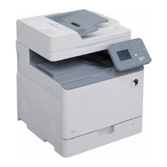
Product Overview > Product Lineup > Host machine > Model type Product Lineup ■ Host machine configuration Configuration Reader+ADF+Printer Host machine T-1-1 ■ Model type imageRUNNER C1335 imageRUNNER C1325 Print Speed 35 ppm 25 ppm T-1-2 F-1-1 Product Overview > Product Lineup > Host machine > Model type... -
Page 16: Option ---------------------------------------------------------------------------------
1 imageRUNNER C1335/C1325 Series 2 ADF Access Handle-A1 3 Cassette Feeding Unit-AJ1 4 Cassette Feeding Unit-AK1 5 Canon FL Cassette-AV1 6 Cassette Heater Unit-39 7 Copy Card Reader-F1 To install the Copy Card Reader-F1, the Copy Card Reader Attachment Kit-H1 is required. - Page 17 Product Overview > Product Lineup > Option > Function expansion system options ■ Function expansion system options ● Hardware Products Product name Remarks and condition 1 Super G3 FAX Board-AQ1 2 Copy Control Interface Kit-C1 3 Handset-J1 eM Controller-C1 T-1-4 ●...
-
Page 18: Features
Product Overview > Features > Product Features Features Product Features Pickup Roller / Separation Roller / Separation Pad Improved serviceability • Easier replacement Toner Container • Reduction in toner soiling achieved by the new toner Improved usability supply system Fixing Assembly ITB Unit Secondary transfer outer Roller Drum Unit (Y/M/C/Bk) -
Page 19: Specifications
Specifications Duplexing method Through-pass duplex Operation noise 71.5dB or less (during printing) Specifications imageRUNNER C1335 series :71.5dB or less (during printing) imageRUNNER C1325 series: 68.5dB or less (during printing) Ozone volume Max 0.001ppm or less Item Specifications Rated power supply Americas: 120 to 127 V, 60 Hz, 7.5 A... -
Page 20: Productivity (Print Speed)
Product Overview > Specifications > Productivity (Print speed) Productivity (Print speed) imageRUNNER C1335IF imageRUNNER C1325/C1325IF Paper type Size Cassette Multi-purpose Tray Cassette Multi-purpose Tray 1-sided 2-sided 1-sided 2-sided 1-sided 2-sided 1-sided 2-sided Thin paper (60 to 63 g/m Plain paper1 (64 to 75 g/m Recycled paper1/Color paper (64 to 75 g/m B5/16K 3 to 26... -
Page 21: Paper Type
Product Overview > Specifications > Paper type > Pickup Paper type Following shows the types of usable papers. See the table below for the custom paper size. Type Feeding direction (mm) Width direction (mm) Custom paper size1 148.0 to 190.4 98.4 to 216.0 Custom paper size2-1 190.5 to 209.9... - Page 22 Product Overview > Specifications > Paper type > Pickup Paper Type Size Feeding direction Width direction Pickup position Auto Duplex 2-Side Setting Multi CST1 CST2 CST3 CST4 (mm) (mm) Plain paper3 (91 to 105 g/m 297.0 210.0 Recycled paper3 (91 to 105 g/m 257.0 182.0 210.0...
- Page 23 Product Overview > Specifications > Paper type > Pickup 1-10 Paper Type Size Feeding direction Width direction Pickup position Auto Duplex 2-Side Setting Multi CST1 CST2 CST3 CST4 (mm) (mm) Transparency 297.0 210.0 LTRR 279.4 215.9 Postcard Postcard 148.0 100.0 200.0 148.0 296.0...
-
Page 24: Parts Name
Product Overview > Parts Name > External View > Reader 1-11 Parts Name ■ Reader External View ■ ADF F-1-5 Original Tray ADF Base Feeder Cover ADF Rear Cover Side Guide Plate F-1-6 Copyboard Glass Unit Reader Rear Cover 1 Reader Rear Cover 2 Reader Motor Cover 1-11... - Page 25 Product Overview > Parts Name > External View > Front view, Left side 1-12 ■ Front view, Left side Front Cover Cassette [15] [14] [16] Face Cover Left Lower Cover [13] Face Cover Left Upper Cover Rear Sub Cover Delivery Cover Reverse Tray [10] Upper Cover...
- Page 26 Product Overview > Parts Name > External View > Rear view, Right side 1-13 ■ Rear view, Right side Rear Cover 1 FAN Cover [14] Environment Heater Cover FAX Connector Cover [13] Multi-purpose Tray Lower Cover Right Front Cover [12] Main Power Switch Cover Right Upper Cover [11]...
-
Page 27: Cross Sectional View
Product Overview > Parts Name > Cross Sectional View 1-14 Cross Sectional View ■ Front Inner [10] [11] F-1-9 [12] Front Inner Right Cover Front Inner Lower Cover [13] Front Inner Upper Cover [16] [15] [14] F-1-10 1-14 Product Overview > Parts Name > Cross Sectional View... -
Page 28: Operation
Product Overview > Parts Name > Operation > Power Switch 1-15 Operation ■ Power Switch ADF Unit Pickup Roller Separation Roller Feed Roller ● Types of Power Switches Separation Pad Delivery Roller Original Tray ADF Base Platen Guide [10] Reader Unit [11] Copyboard Glass [12]... -
Page 29: Control Panel
Product Overview > Parts Name > Operation > Description of Control Panel 1-16 ● Points to Note on Turning ON/OFF the Power Switch ■ Description of Control Panel • Be sure to turn OFF the Main Power Switch when turning off the power. ●... -
Page 30: Main Menu
Product Overview > Parts Name > Operation > Description of Control Panel 1-17 ● Main Menu F-1-13 F-1-14 Name Remarks Copy Super G3 FAX Board-AQ1 is required. Scan Memory Media Print Secure Print Paper Settings Home Screen Settings ID Card Copy T-1-11 1-17 Product Overview >... - Page 31 Product Overview > Parts Name > Operation > Description of Control Panel 1-18 ● Settings / Registration Menu [10] [11] F-1-17 Name Remarks F-1-15 Network Settings Preferences Timer Settings Common Settings Copy Settings Fax Settings Super G3 FAX Board-AQ1 is required. Scan Settings Memory Media Print Settings Printer Settings...
-
Page 32: Technical Explanation
Technical Explanation ■ Basic Configuration ■ Original Exposure and Feed System ■ Main Controller ■ Laser Exposure System ■ Image Formation System ■ Fixing System ■ Pickup / Feed System ■ External Auxiliary System ■ Embedded RDS Technical Explanation... -
Page 33: Functional Configuration
Technical Explanation > Basic Configuration > Functional Configuration Basic Configuration Functional Configuration This machine consists of 6 major blocks: Original Exposure and Feed System, Controller System, Laser Exposure System, Image Formation System, Fixing System, and Pickup Feed System. Original Exposure and Feed System Reader Delivery Fixing... -
Page 34: Original Exposure And Feed System
Technical Explanation > Original Exposure and Feed System > Construction > Specifications/controls/functions Original Exposure and Feed System Item Specification/function ADF original tray capacity A4/LTR-R: 50 sheets (80 g/m LGL: 30 sheets (80 g/m Construction ADF original processing mode 1-sided original processing 2-sided original processing ADF original size detection ■... - Page 35 Technical Explanation > Original Exposure and Feed System > Construction > Major Components ■ Major Components ● ADF unit Following shows major components of ADF unit. ● Reader Unit Following shows major components of reader unit. 1) Layout Drawing of Major Parts Drive Pulley Separation Pad Contact Image Sensor (CIS)
- Page 36 Technical Explanation > Original Exposure and Feed System > Construction > Major Components 2) Layout Drawing of Sensors Item Notation Specification/function ADF Motor Pulse Motor: Feeds originals. PS03 Disengagement Solenoid When reverse feeding in the upward direction, disengages the roller from the Delivery Reverse Roller. Document Sensor PS03 Photo Interrupter: Detects whether an original is present.
-
Page 37: Basic Operation
Technical Explanation > Original Exposure and Feed System > Basic Operation > Basic Sequence Basic Operation 3) The Reader Motor activates and moves the carriage to the right. 4) After the CIS HP Sensor (PS01) is turned OFF, the carriage moves the designated ■... - Page 38 Technical Explanation > Original Exposure and Feed System > Basic Operation > Basic Sequence ● Basic Sequence at Start Key ON (Book mode) ● Basic Sequence at Start Key ON (ADF mode) Start ADF scan CIS, AFE ON CIS, AFE ON Black shading is executed Black shading is executed LED ON...
- Page 39 Technical Explanation > Original Exposure and Feed System > Basic Operation > ADF Operation Mode ■ ADF Operation Mode ADF has 4 operation modes. Operation mode names and outline of operations and associated print modes are given in the following table: Operation mode name Outline of operation Associated print mode...
- Page 40 Technical Explanation > Original Exposure and Feed System > Basic Operation > ADF Operation Mode ● Single-sided original reading • Operation of single-sided original reading (2 originals) Single-sided reading operation Single-sided reading operation (when 2 sheet of original is placed) 2/2 (when 2 sheet of original is placed) 1/2 - Setting of original - Start of reading of the front side...
- Page 41 Technical Explanation > Original Exposure and Feed System > Basic Operation > ADF Operation Mode 2-10 ● Double-sided original reading • Operation of double-sided original reading (2 originals) Duplex reading operation Duplex reading operation (when 2 sheet of original is placed) (when 2 sheet of original is placed) - Feed of the 1st Sheet - Feed to the reverse point...
- Page 42 Technical Explanation > Original Exposure and Feed System > Basic Operation > ADF Operation Mode 2-11 Duplex reading operation Duplex reading operation (when 2 sheet of original is placed) (when 2 sheet of original is placed) - Delivery of the 1st sheet Waiting for reading of the front side - Re-pickup of the 2nd Sheet - End of reading of the back side of...
- Page 43 Technical Explanation > Original Exposure and Feed System > Basic Operation > ADF Operation Mode 2-12 Duplex reading operation (when 2 sheet of original is placed) - Idle feed of the 2nd Sheet & engagement of Delivery Roller - Passing of the 2nd Sheet reading position - Delivery of the 2nd sheet &...
-
Page 44: Reader Unit Controls
Technical Explanation > Original Exposure and Feed System > Reader Unit controls > Original Detection 2-13 Reader Unit controls ● Reader Motor Control The rotation/stopping and rotation direction/speed of Reader Motor (M01) are controlled ■ Scanner Drive Control based on signals from the ASIC. ●... -
Page 45: Image Processing
Technical Explanation > Original Exposure and Feed System > Image Processing > Overview 2-14 Image Processing 6ch CIS 4ch CIS Control Signal 2 Drive IC ■ Overview Sensor Sensor Sensor Sensor The image processing is executed by the CIS Unit (AFE) and the Main Controller PCB. Sensor Sensor The functions related to the image processing are shown below:... - Page 46 Technical Explanation > Original Exposure and Feed System > Image Processing > Image Processing by the CIS Unit (AFE) 2-15 ■ Image Processing by the CIS Unit (AFE) Component Function Illuminates the original. ● Contact Image Sensor (CIS) Light guide Illuminates the entire image line with the LED light.
- Page 47 Technical Explanation > Original Exposure and Feed System > Image Processing > Image Processing by the Main Controller PCB (Reader ASIC) 2-16 ● Analog Control Performed by the CIS ■ Image Processing by the Main Controller PCB (Reader ASIC) The flow of analog image processing performed by the contact image sensor (CIS) is as ●...
-
Page 48: Shading Correction
Technical Explanation > Original Exposure and Feed System > Image Processing > Image Processing by the Main Controller PCB (Reader ASIC) 2-17 ● Shading Correction White shading (for stream reading) The shading correction of stream reading is performed using the white level adjustment value Due to the characteristics of each of the elements in the CIS, variations occur in the reading (factory adjustment value). - Page 49 Technical Explanation > Original Exposure and Feed System > Image Processing > Image Processing by the Main Controller PCB (Reader ASIC) 2-18 ● Dust Detection Control 1) Before the original is fed, the Platen Guide is read through the Reading Glass to detect points where there is a possibility of dust.
- Page 50 Technical Explanation > Original Exposure and Feed System > Image Processing > Image Processing by the Main Controller PCB (Reader ASIC) 2-19 Dust Detection Preventive Process If dust is detected in paper of the last job, the reading position of the following stream reading jobs is changed to avoid the dust.
-
Page 51: Control Of Adf
Technical Explanation > Original Exposure and Feed System > Control of ADF > Pickup Control 2-20 Control of ADF ● Pickup operation (1-sided/2-sided stream reading) When the key to start printing is pressed while an original is placed on the Original Tray, ■... - Page 52 Technical Explanation > Original Exposure and Feed System > Control of ADF > Feed Control 2-21 ■ Feed Control ● At 1-sided stream reading The drive of the ADF Motor (M02) rotates the Feed Roller, and feeds an original to the reading position.
- Page 53 Technical Explanation > Original Exposure and Feed System > Control of ADF > Feed Control 2-22 ● At 2-sided stream reading The drive (clockwise rotation) of the ADF Motor (M02) rotates the Feed Roller, and feeds an original. When the Document End Sensor (PS02) is turned ON, the ADF Motor (M02) is stopped to stop the original.
- Page 54 Technical Explanation > Original Exposure and Feed System > Control of ADF > Reverse Control 2-23 ■ Read Control ■ Reverse Control When the edge of an original reaches the reading position, stream reading is started by ● Basic operation sending the image leading edge signal to the host machine.
- Page 55 Technical Explanation > Original Exposure and Feed System > Control of ADF > Reverse Control 2-24 ● Reverse/Feed Counterclockwise Rotation The drive (counterclockwise rotation) of the ADF Motor (M02) rotates the Feed Roller, and feeds an original. When the Document End Sensor (PS02) is turned ON, the ADF Motor (M02) is stopped to stop the original.
-
Page 56: Original Size Detection
Technical Explanation > Original Exposure and Feed System > Control of ADF > Original Detection 2-25 ■ Feed/Delivery of Original ■ Original Detection ● Basic Operation ● Detection of presence/absence of original After stream reading on the Copyboard Glass is completed, the Feed Roller rotates to send As the actuator is pushed up by placing an original on the Original Tray, the Original Sensor an original to the Delivery Tray. -
Page 57: Service Tasks
Technical Explanation > Original Exposure and Feed System > Service Tasks > Actions at Parts Replacement 2-26 Service Tasks ■ Jam Detection This machine detects jam using the Document End Sensor (PS02) and the Document ■ Periodically Replaced Parts Sensor (PS03). The check timing to detect jam is already stored in the Main Controller PCB, None. -
Page 58: Main Controller
Technical Explanation > Main Controller > Overview > Configuration / Function 2-27 Main Controller Item Function Main Controller PCB System Control / Memory Control / Printer Output Image Processing Control, Reader Image Input Processing Overview T-2-12 ■ Configuration / Function Main Controller PCB Memory PCB F-2-36... - Page 59 Technical Explanation > Main Controller > Overview > Main controller PCB 2-28 ■ Main controller PCB USB PCB Function J908 J902 USB I/F J908 USB PCB J909 J911 LAN I/F J936 ECO PCB J918 FAX Unit I/F J924 J921 Off-hook PCB J950 J924 Control Panel I/F...
-
Page 60: Laser Exposure System
Technical Explanation > Laser Exposure System > Overview 2-29 Laser Exposure System Overview Photosensitive Drum Laser exposure system forms the electrostatic latent image on the photosensitive drum by the laser exposure. This system is composed of the laser assembly and the scanner motor assembly that are unified as the laser scanner unit. - Page 61 Technical Explanation > Laser Exposure System > Overview 2-30 Laser A Laser B F-2-39 [1] Y/M/C/Bk Laser Driver PCB [4] Reflection Mirror [2] BD Circuit [5] Polygon Mirrors [3] Imaging Lens [6] Scanner Motor 2-30 Technical Explanation > Laser Exposure System > Overview...
-
Page 62: Specification
Technical Explanation > Laser Exposure System > Specification > 1-Polygon 4-Laser Method 2-31 Specification ■ 1-Polygon 4-Laser Method This method uses 1 scanner motor (polygon motor) and 4 laser diodes to execute laser Item Description scanning. This method allows to emit the 4 lasers on the multi-facet mirror on one scanner Wavelength 780 to 800nm motor contributing to space-saving. -
Page 63: Various Controls
Technical Explanation > Laser Exposure System > Various Controls > Laser ON/OFF control 2-32 Various Controls ■ Laser ON/OFF control ● Purpose ■ Overview Laser light is turned ON / OFF according to the combination of laser control signal. Item Operation description Laser ON / OFF control Laser light is turned ON / OFF according to the combination of... - Page 64 Technical Explanation > Laser Exposure System > Various Controls > Horizontal scanning synchronous control 2-33 ■ Horizontal scanning synchronous control BD Sensor ● Purpose To align the writing start position in horizontal scanning direction. DC Controller PCB (UN04) Bk Laser Y/M/C/K ●...
- Page 65 Technical Explanation > Laser Exposure System > Various Controls > Laser scanner motor control 2-34 ■ Vertical Scanning Synchronous Control ■ Laser scanner motor control ● Purpose ● Purpose This is to align the writing start position in vertical scanning direction. This is to rotate the scanner mirror by the specified speed.
- Page 66 Technical Explanation > Laser Exposure System > Various Controls > APC(Auto Power Control) Control 2-35 ■ APC(Auto Power Control) Control Related error code ● Purpose • E100-0100: BD error This is to make the laser light for 1 line consistent amount. The BD lock was unlocked although it had been locked once.
- Page 67 Technical Explanation > Laser Exposure System > Various Controls > Dustproof shutter control 2-36 ■ BD correction control ■ Dustproof shutter control ● Purpose ● Purpose This is to correct the displacement of writing start position of each color laser due to the angle This is to prevent the residue toner from sticking to the dust-prevention glass.
-
Page 68: Service Tasks
Technical Explanation > Laser Exposure System > Service Tasks > Actions at Parts Replacement 2-37 Service Tasks ■ Periodically Replaced Parts None. ■ Consumable Parts None. ■ Periodical Servicing None. Perform as needed. ■ Actions at Parts Replacement • Actions at Laser Scanner Unit Replacement 2-37 Technical Explanation >... -
Page 69: Image Formation System
Technical Explanation > Image Formation System > Overview > Specifications 2-38 Image Formation System ■ Specifications Item Function/Method Photosensitive Material Overview Drum Drum diameter 30mm dia Cleaning Cleaning blade ■ Overview Process speed 35 ppm model: 200 mm/s 25 ppm model: 135 mm/s Drum Heater None Image formation system of this machine uses the Dry, 2-component AC developing for... -
Page 70: Print Process
Technical Explanation > Image Formation System > Overview > Print Process 2-39 ■ Parts Configuration ■ Print Process ● Major Parts ● Overview Hopper Unit Delivery Fixing block 7.Fixing ITB cleaning block Transfer block Toner Container 6.Separation 8.ITB cleaning 5.Secondary transfer 4.Primary 4.Primary 4.Primary... - Page 71 Technical Explanation > Image Formation System > Overview > Print Process 2-40 ● Bias Types Static latent image 1 Primary To charge the surface of photosensitive drum to be uniformed formation block charging negative potential The following 5 types of bias are used with this machine. 2 Laser To create static latent image on the surface of photosensitive Bias...
-
Page 72: Controls
Technical Explanation > Image Formation System > Controls > Primary Charging 2-41 Controls ■ Primary Charging ● Overview ■ Overview This machine uses the roller charging method for primary charging. Primary charging Primary charging bias control Photosensitive Drum Image stabilization control D-max control PASCAL control D-half control... - Page 73 Technical Explanation > Image Formation System > Controls > Drum Unit (Developing/Drum) 2-42 ● Primary Charging Bias Control ■ Drum Unit (Developing/Drum) DC charging (no AC charging) is a distinguishing feature of the primary charging of this ● Drum Unit Overview machine.
-
Page 74: Developing Bias Control
Technical Explanation > Image Formation System > Controls > Drum Unit (Developing/Drum) 2-43 ● Developing Overview/ Drive Configuration ● Developing bias control A toner image is formed on the Photosensitive Drum by attaching toner to the Developing Developing Cylinder Cylinder. Control description Developing Cylinder Clutch The developing bias (AC, DC negative), which has been generated on the Developing... - Page 75 Technical Explanation > Image Formation System > Controls > Drum Unit (Developing/Drum) 2-44 ● Drum Overview ● Drive Configuration Photosensitive Drum Photosensitive Drum CL Drum Motor Bk Drum _ ITB Motor Cleaning Screw Cleaning Screw Cleaning Blade Cleaning Primary Charging Roller Blade Primary Charging Roller F-2-60...
- Page 76 Technical Explanation > Image Formation System > Controls > Drum Unit (Developing/Drum) 2-45 ● Drum Unit Detection NOTE: Whether the Drum Unit is installed or not is detected. Drum Unit detection may not be executed at times such as at recovery from sleep mode (of 4 or more hours).
- Page 77 Technical Explanation > Image Formation System > Controls > Drum Unit (Developing/Drum) 2-46 ● Drum Unit Life Detection *4: During the period from when a pre-toner low alarm is sent to when a replacement completion alarm is sent, the next pre-toner low alarm is not sent. It is printed in JAM/ERR Life of the Drum Unit (Photosensitive Drum) is detected.
- Page 78 Technical Explanation > Image Formation System > Controls > Transfer/Separation 2-47 ■ Transfer/Separation ● Drive Configuration Developing Motor Bk Drum _ ITB Motor ● Overview The ITB Unit transfers a toner image on the Photosensitive Drum onto the ITB. Then, the toner image is transferred on the paper.
-
Page 79: Atvc Control
Technical Explanation > Image Formation System > Controls > Transfer/Separation 2-48 ● Primary Transfer Roller Disengagement Control ● ATVC Control The Primary Transfer Roller is usually disengaged. Primary Transfer ATVC The transfer voltage required to prevent transfer failure due to environmental changes and to Timing of engagement obtain the target transfer current value is set. - Page 80 Technical Explanation > Image Formation System > Controls > Transfer/Separation 2-49 Secondary Transfer ATVC ● Primary Transfer Bias Control The transfer voltage required to prevent transfer failure due to environmental changes or The primary transfer bias is divided into each color (Y, M, C, Bk) to be generated on the paper type and to obtain the target transfer current value is set.
- Page 81 Technical Explanation > Image Formation System > Controls > Transfer/Separation 2-50 ● Secondary Transfer Bias Control ● ITB Displacement Correction Toner on the ITB is transferred to a paper. The newly developed ITB displacement control mechanism mechanically prevents full The secondary transfer bias, which has been generated on the Secondary Transfer High- displacement of the belt.
-
Page 82: Itb Cleaning
Technical Explanation > Image Formation System > Controls > Transfer/Separation 2-51 Mechanism for preventing displacement ● ITB Cleaning 1. The ITB is displaced toward one side. Residual toner on the ITB is removed. 2. The belt is displaced and driven onto the sliding member at the end. This sliding member does not rotate, and friction is generated between the belt and the sliding Control description member. - Page 83 Technical Explanation > Image Formation System > Controls > Transfer/Separation 2-52 ● Secondary Transfer Outer Roller Cleaning Control ● Separation Soiling at the back of the sheet caused by soiling of the Secondary Transfer Outer Roller can This control separates paper from the ITB by elastic force of the paper (curvature separation be prevented.
-
Page 84: Drum Cleaning
Technical Explanation > Image Formation System > Controls > Image Stabilization Control 2-53 ■ Drum Cleaning ■ Image Stabilization Control ● Drum cleaning control ● Overview To clean residual toner on the photosensitive drum Image failure due to change of the environment or deterioration of the Photosensitive Drum is Residual toner on the drum is scraped by the drum cleaning blade. - Page 85 Technical Explanation > Image Formation System > Controls > Image Stabilization Control 2-54 ● Control timing ● D-max Control Execution items for image stabilization control differ according to the environment and The optimal laser output is determined. condition of image formation parts. Following shows the control items at each sequence and estimated downtime.
- Page 86 Technical Explanation > Image Formation System > Controls > Image Stabilization Control 2-55 Start Main Controller PCB (UN81) Output of patch pattern data DC Controller PCB (UN04) Patch pattern is created Developing Laser output Cylinder Registration Patch Sensor Unit (Front) (UN31) Registration Patch Sensor Unit (Rear) (UN32) Primary Patch scanning...
- Page 87 Technical Explanation > Image Formation System > Controls > Image Stabilization Control 2-56 ● PASCAL control NOTE: Gradation density characteristics on the image are stabilized. The following 3 types of patch patterns are formed with this control: This control is executed when the following is selected in UI menu: Auto Adjust Gradation > •...
- Page 88 Technical Explanation > Image Formation System > Controls > Image Stabilization Control 2-57 ● D-half Control Start Optimal image gradation is determined. Main Controller PCB (UN81) Control timing Output of patch pattern data 1) During installation and when replacing the Drum Unit 2) At last rotation on a specified print basis (1000 sheets or more) DC Controller PCB (UN04) 3) At last rotation when PASCAL control is executed...
- Page 89 Technical Explanation > Image Formation System > Controls > Image Stabilization Control 2-58 Start Main Controller PCB (UN81) Output of patch pattern data DC Controller PCB (UN04) Patch pattern is created Registration Patch Sensor Unit (Y) D-half correction table (Front,Rear)(UN31,UN32) Actual gradation Registration Patch scanning...
- Page 90 Technical Explanation > Image Formation System > Controls > Image Stabilization Control 2-59 The flow to calculate correction value for ARCDAT control ● ARCDAT Control (Automatic and Reciprocal Color Density Adjustment Technology) Start While reducing downtime, the ideal gradation characteristics are realized. Main Controller PCB (UN81) Control timing Output of patch pattern data...
- Page 91 Technical Explanation > Image Formation System > Controls > Image Stabilization Control 2-60 Start Main Controller PCB (UN81) Output of patch pattern data DC Controller PCB (UN04) Patch pattern is created Registration Patch Sensor Unit (Front,Rear)(UN31,UN32) Reference data for Registration example) Patch scanning ARCDAT of copy pattern...
- Page 92 Technical Explanation > Image Formation System > Controls > Image Stabilization Control 2-61 ● Color Displacement Correction Control Control description 2: Color displacement correction based on temperature prediction Uneven exposure of the Laser Scanner Unit and color displacement caused by uneven 1) The degree of color displacement is measured based on the operating condition (mainly rotation of the drum or the ITB is corrected.
- Page 93 Technical Explanation > Image Formation System > Controls > Toner Supply Assembly 2-62 ■ Toner Supply Assembly ● Toner Head Assembly Opening This control automatically opens/closes the head assembly of toner container. ● Overview Toner is supplied from the Toner Container to the Developing Assembly. The toner level of the Control timing Toner Container is detected at the same time.
- Page 94 Technical Explanation > Image Formation System > Controls > Toner Supply Assembly 2-63 ● Toner Log Detection ● ATR Control (Auto Toner Replenishment) A Toner Log is detected. Toner is supplied to the Developing Assembly to make the developer (toner + carrier) in the assembly to meet at an ideal ratio.
- Page 95 Technical Explanation > Image Formation System > Controls > Toner Supply Assembly 2-64 ● Driving the Toner Bottles Toner Log Connector Bottle Rotation Sensor This machine has only 2 Toner Bottle Motors, and toner is supplied by driving Toner Bottles of (Y,M,C,Bk) (Y,M,C,Bk) (UN38,39,40,41)
- Page 96 Technical Explanation > Image Formation System > Controls > Toner Supply Assembly 2-65 The operation is going to be explained taking Bk and C as an example. 3. When the motor rotates in the reverse direction, the gear in the center moves to the 1.
- Page 97 Technical Explanation > Image Formation System > Controls > Toner Supply Assembly 2-66 ● Toner Supply Control The Bottle Rotation Sensor (Y/M/C/Bk) (PS06/PS07/PS08/PS09) starts while it is turned ON at the time of feeding. Driving the Bottle Motor (YM) (M09) or the Bottle Motor (CK) (M10) Toner is supplied from the Toner Container to the Developing Assembly.
- Page 98 Technical Explanation > Image Formation System > Controls > Toner Supply Assembly 2-67 ● Toner Level Detection ● Detection of the completion of toner replacement Detection Prior delivery alarm Display Remaining Toner Empty toner Detection of the completion of replacement Detection timing When a replacement of Toner Container is detected description...
- Page 99 Technical Explanation > Image Formation System > Controls > Waste Toner Feeding Area 2-68 ■ Waste Toner Feeding Area ● Waste Toner Container Full Level Detection To detect toner level accumulated in the waste toner case. ● Overview Waste Toner Waste Toner Container To feed waste toner of the drum cleaning unit and the ITB cleaning unit to the Waste Toner Container.
- Page 100 Technical Explanation > Image Formation System > Controls > Warm-up Rotation 2-69 ● Detection of the completion of waste toner replacement ■ Warm-up Rotation Detection timing When the Waste Toner Sensor PCB (UN17) is turned ON for 3 seconds after ●...
-
Page 101: Service Tasks
Technical Explanation > Image Formation System > Service Tasks > Periodical Servicing 2-70 Service Tasks ■ Periodically Replaced Parts None. ■ Consumable Parts Parts name Parts Quantity Estimated life Remarks number ITB Unit FM1-A153 1 150,000 sheets Secondary transfer outer Roller FC0-5848 150,000 sheets Waste Toner Container FM0-0015... -
Page 102: Fixing System
Technical Explanation > Fixing System > Overview > Specifications 2-71 Fixing System ■ Specifications Item Function/method Fixing method On-demand fixing Overview Fixing speed 35-ppm model 1/1 speed 200 mm/sec 2/3 speed 135 mm/sec ■ Features 1/2 speed 100 mm/sec 25-ppm model 1/1 speed This machine uses the on-demand fixing method. - Page 103 Technical Explanation > Fixing System > Overview > Major Components 2-72 ■ Major Components Fixing Pressure Release Sensor (PS13) Fixing Heater (H01) Pressure Roller Fixing Thermoswitch (TP01) Delivery Sensor (PS12) Sub Thermistor (Rear) (TH02) Fixing Film Main Thermistor (TH01) F-2-105 Sub Thermistor (Front) (TH03) F-2-106...
-
Page 104: Controls
Technical Explanation > Fixing System > Controls > Fixing Temperature Control (temperature control) 2-73 Controls ● Standby Temperature Control This is a control to pre-heat the Fixing Assembly to reduce time to start printing. ■ Fixing Temperature Control (temperature control) •... - Page 105 Technical Explanation > Fixing System > Controls > Standby Temperature Control 2-74 ■ Standby Temperature Control ● Flying Start Purpose: Fixing To reduce time to print the first sheet (FCOT). temperature STBY INTR PRNT Startup conditions: • When Control Panel Numeric Keypad/Touch Panel is pressed Flaying start control •...
-
Page 106: Print Temperature Control
Technical Explanation > Fixing System > Controls > Print Temperature Control 2-75 ■ Print Temperature Control ● Print Temperature Control To set optimal target temperature to prevent fixing failure or offset, and keep the specified target temperature during printing A. Setting the target temperature A target temperature is determined according to the paper type/size, time which elapsed from when fixing temperature control (including standby control) finished the last time, and fixing temperature when startup control started. - Page 107 Technical Explanation > Fixing System > Controls > Print Temperature Control 2-76 ● Target temperature during printing Related Service Mode: The control temperature is determined according to the fixing mode and fixing temperature (Lv.1) COPIER > DISPLAY > ANALOG at the start of Startup control. 11 fixing modes are available according to the selected pickup >...
- Page 108 Technical Explanation > Fixing System > Controls > Down Sequence Control 2-77 ■ Down Sequence Control Purpose: To prevent fixing offset and deterioration of the Fixing Film by controlling temperature ● Down sequence when feeding small-size paper increase at a non paper feed area at continuous printing of small-size paper (paper that has smaller than A4R/LTR of width-direction length) Fixing Film Pressure Roller...
- Page 109 Technical Explanation > Fixing System > Controls > Down Sequence Control 2-78 Detected temperature Detected temperature Paper Paper Speed Paper type Speed Paper type size size 1st stage 2nd stage 3rd stage 4th stage 5th stage 1st stage 2nd stage 3rd stage 4th stage 5th stage stage stage A4 </= *...
- Page 110 Technical Explanation > Fixing System > Controls > Down Sequence Control 2-79 Detected temperature Detected temperature Paper Paper Speed Paper type Speed Paper type size size 1st stage 2nd stage 3rd stage 4th stage 5th stage 1st stage 2nd stage 3rd stage 4th stage 5th stage stage stage A5 </= *...
- Page 111 Technical Explanation > Fixing System > Controls > Down Sequence Control 2-80 Termination condition: ● Down sequence when switching paper size The termination condition is when the job ends. Purpose: When feeding a sheet with a wider width than a preceding sheet during continuous printing, Related Service Mode: temperature at the non paper-feed area of the preceding sheet increases, and it can cause •...
- Page 112 Technical Explanation > Fixing System > Controls > Down Sequence Control 2-81 Termination conditions: ● Film unit engagement / disengagement control • When the highest of the temperatures detected by the Sub Thermistor (Rear) (TH02) The Fixing Film Unit is disengaged from the Pressure Roller under a specific conditionfor and the Sub Thermistor (Front) (TH03) has become the specified temperature (150 the purpose of preventing deformation of the Fixing Film/Pressure Roller due to heat deg C) or less.
- Page 113 Technical Explanation > Fixing System > Controls > Pre-fixing arch level control 2-82 ■ Pre-fixing arch level control <Pressure state> <Pressure Release state> Purpose: Fixing Slit Pressure Release To prevent image failure and feeding failure Sensor (PS13) Since the feeding speed of the Pressure Roller and that of the Secondary Transfer Outer Roller are not the same when a sheet is fed to the Fixing Assembly, image failure, paper wrinkle, image stretching, etc.
- Page 114 Technical Explanation > Fixing System > Controls > Arch Sensor control 2-83 ■ Arch Sensor control Operation: Fixing Film The Arch Sensor (PS11) detects a paper arch between the transfer nip and fixing nip to Pressure Roller change the drive speed of the Fixing Motor. 1) When the paper's leading edge goes over 65 mm from the secondary transfer nip area by 65 mm, drive speed of the Fixing Motor is reduced by 1.0% against the process Fixing Motor...
-
Page 115: Protection Function
Technical Explanation > Fixing System > Controls > Protection function 2-84 Sensor : OFF Sensor : ON ■ Protection function Slack of paper is small Slack of paper is large Clearing Code Description of error E001 Fixing Assembly high temperature error A001 Main Thermistor detected a temperature of 265 deg C or higher for 0.1 PS11 sec or longer (software). - Page 116 Technical Explanation > Fixing System > Controls > Protection function 2-85 Clearing Code Description of error E009 Film unit engagement / disengagement error 0001 Signal of the Fixing Pressure Release Sensor could not be detected at pressure application operation of the Fixing Pressure Release Cam, required and the operation was not completed within 4 sec from the start of counterclockwise rotation of the Fixing Motor.
-
Page 117: Service Tasks
Technical Explanation > Fixing System > Service Tasks > Periodical Servicing 2-86 Service Tasks ■ Periodically Replaced Parts None. ■ Consumable Parts Parts name Parts number Quantity Estimated life Remarks Fixing Assembly FM0-0033(100V) 150,000 sheets FM0-0072(120V) FM0-0073(230V) T-2-43 ■ Periodical Servicing None. -
Page 118: Pickup / Feed System
Technical Explanation > Pickup / Feed System > Overview > Parts Configuration 2-87 Pickup / Feed System ■ Parts Configuration ● Rollers Layout drawing Overview ■ Specifications Item Description Paper storage method Front-loading method Pickup method Cassette Retard separation Multi-purpose Tray Retard separation Stacking capacity Cassette... - Page 119 Technical Explanation > Pickup / Feed System > Overview > Parts Configuration 2-88 ● Sensors Layout Drawing ● Route of Drive PS14 PS12 PS11 PS01 SL02 PS04 PS05 PS03 PS10 SW09 PS20 PS02 PS18 F-2-118 PS01 Duplex Sensor PS11 Arch Sensor F-2-119 PS02 Cassette 1 Paper Sensor PS12 Delivery Sensor...
-
Page 120: Paper Path
Technical Explanation > Pickup / Feed System > Overview > Paper Path 2-89 ■ Paper Path Reversing point Delivery point Pickup from manual feeder Pickup from cassette F-2-120 2-89 Technical Explanation > Pickup / Feed System > Overview > Paper Path... -
Page 121: Controls
Technical Explanation > Pickup / Feed System > Controls > Overview 2-90 Controls ■ Overview Area Detection/Control Cassette Pickup Pickup Retry Control Paper Detection Control Assembly Paper Size Detection Control Paper Level Detection Control Lifter Control Reverse Multi-purpose Tray Pickup Retry Control Paper Size Detection /Duplex Assembly Pickup Assembly... - Page 122 Technical Explanation > Pickup / Feed System > Controls > Cassette Pickup Assembly 2-91 ■ Cassette Pickup Assembly ● Pickup Retry Control If the Cassette 1 Pickup Sensor (PS05) is not turned ON within a specified period of time ● Overview after the start of pickup operation of the top paper, operation of the Cassette 1 Multi-purpose Paper inside a cassette is lifted up by the Lifter Plate.
- Page 123 Technical Explanation > Pickup / Feed System > Controls > Cassette Pickup Assembly 2-92 ● Paper Size Detection Control A5-R The paper size in the cassette is automatically detected by the "Cassette 1 Size Switch STMT-R (SW09)" after the position of the Guide Plate is adjusted and the cassette is installed in the host machine.
- Page 124 Technical Explanation > Pickup / Feed System > Controls > Cassette Pickup Assembly 2-93 Paper size*1 All modes AB configuration Inch-configuration AK configuration A5-R 210.0 STMT-R 215.9 B5-R 257.0 Paper load error Paper load error EXEC-R 267.0 Paper load error 16K-R 270.0 Paper load error...
- Page 125 Technical Explanation > Pickup / Feed System > Controls > Cassette Pickup Assembly 2-94 ● Paper Level Detection Control Cassette 1 Paper Lifting Plate Surface Sensor Detection Lever Paper level inside the cassette is detected by the sensors shown in the following table. (PS18) Cassette 1 The paper level in the cassette is detected by the Cassette 1 Lifter Motor (M11), Cassette 1...
- Page 126 Technical Explanation > Pickup / Feed System > Controls > Cassette Pickup Assembly 2-95 Cassette 1 Cassette 1 Paper Sensor Paper Sensor (PS02) (PS02) Cassette 1 Paper Cassette 1 Paper Surface Sensor Surface Sensor (PS18) (PS18) Paper Paper Paper Paper Cassette 1 Paper Cassette 1 Paper Level Sensor...
- Page 127 Technical Explanation > Pickup / Feed System > Controls > Multi-purpose Tray Pickup Assembly 2-96 ● Paper Detection Control ■ Multi-purpose Tray Pickup Assembly Paper is detected by the Cassette 1 Size Switch (SW09), Cassette 1 Paper Surface Sensor ● Overview (PS18) and Cassette 1 Paper Sensor (PS02).
-
Page 128: Registration Control
Technical Explanation > Pickup / Feed System > Controls > Fixing/Registration Assembly 2-97 ● Pickup Retry Control ■ Fixing/Registration Assembly If the Pre-Registration Sensor (PS03) is not turned ON within the specified period of time ● Registration Control after the start of pickup operation, the Cassette 1_Multi-purpose Tray Pickup Motor (M05) It is a control to align paper and image on the ITB at a specified timing. -
Page 129: Delivery Assembly
Technical Explanation > Pickup / Feed System > Controls > Delivery Assembly 2-98 ● Stop Registration Control ■ Delivery Assembly It is a control to stop paper at the registration position, align paper and image on the ITB at a ●... - Page 130 Technical Explanation > Pickup / Feed System > Controls > Reverse/Duplex Assembly 2-99 ■ Reverse/Duplex Assembly ● Duplex Reverse Control Paper is reversed outside the machine using the Reverse Mouth. ● Reverse Flapper Operation Paper stops at the duplex reverse stop position after a specified time has elapsed since The Reverse Flapper operates in accordance with the Reverse Motor (M08).
- Page 131 Technical Explanation > Pickup / Feed System > Controls > Reverse/Duplex Assembly 2-100 ● Duplex standby control ● Duplex Pre-standby control If it is possible to secure necessary paper interval by estimating the paper interval with the When the succeeding paper has not finished the registration control (non-stop registration preceding paper when the Duplex Sensor (PS01) is ON, the paper is re-picked up to the pre- control and stop registration control), the paper stops before the nip of the Duplex Feed registration.
- Page 132 Technical Explanation > Pickup / Feed System > Controls > Jam Detection 2-101 The Duplex Solenoid (SL02) is turned ON 100 msec before the leading edge of the fed paper ■ Jam Detection reaches the duplex standby position. After the Duplex Solenoid (SL02) is turned ON, the drive ●...
-
Page 133: Service Tasks
Technical Explanation > Pickup / Feed System > Service Tasks > Periodical Servicing 2-102 Service Tasks ACC ID Jam Code Type Sensor Name Sensor ID 0CC1 Sequence Software sequence error (Automatic adjustment: Transfer-related) ■ Periodically Replaced Parts 0CC2 Sequence Software sequence error (Automatic adjustment: Image formation-related) None. -
Page 134: External Auxiliary System
Technical Explanation > External Auxiliary System > Controls > Software counter 2-103 External Auxiliary System Display number of each counter (in service mode) / item Country Target Counter Counter Counter Counter Counter Counter Counter Counter Code Controls 240V UK model Total Total Scan... - Page 135 Technical Explanation > External Auxiliary System > Controls > Software counter 2-104 <Explanation of the list> Display number of each counter (in service mode) / item Country Target Counter Counter Counter Counter Counter Counter Counter Counter • Large: Large size paper (when paper length exceeds 324 mm in paper feed direction) Code •...
- Page 136 Technical Explanation > External Auxiliary System > Controls > Fan 2-105 ■ Fan Copy/print Service Stand Post Deep Initial Reader Sleep1 name rotation rotation rotation Sleep ● Location of Fans Drum Unit Suction Cooling Fan Drive Unit Cooling Fan Delivery FM05 Cooling Fan Duplex...
- Page 137 Technical Explanation > External Auxiliary System > Controls > Power supply 2-106 ■ Power supply ● Internal power supply Host Machine 3.3V (Remote) Cassette Heater Environment Switch Cassette Pedestal 24V (Interlock) Cassette Heater 5V (Interlock) Main Power Switch 3.3V Main Controller PCB All-night Power Supply AD→DC...
- Page 138 Technical Explanation > External Auxiliary System > Controls > Power-Saving Mode 2-107 ■ Power supply connection with the options ■ Power-Saving Mode Reader/ADF This is the function to save power consumed by the printer. The table below lists various power-saving modes. Power-Saving Mode Status Stand-by...
-
Page 139: Embedded Rds
Technical Explanation > Embedded RDS > Product Overview > Major Functions 2-108 Embedded RDS ■ Features and benefits E-RDS embedded with a network module in advance can realize a front-end processing Product Overview of e-Maintenance/ imageWARE Remote system without attaching any extra hardware equipment. -
Page 140: Limitations
Technical Explanation > Embedded RDS > Limitations > Service Mode Menu Transmission Function 2-109 Limitations Transmission timing Transmitting data Error retry When the first communication test is done. COPIER Display ANALOG (For transmission process, 5 minutes after the ■ Service Mode Menu Transmission Function HV-STS execution) 1) In the following cases, service mode menu data is not transmitted. -
Page 141: Service Cautions
Technical Explanation > Embedded RDS > E-RDS Setup > Confirmation and preparation in advance 2-110 Service cautions E-RDS Setup ■ Confirmation and preparation in advance 1) After clearing RAM of the Main Controller PCB, initialization of the E-RDS setting (ERDS- DAT) and a communication test (COM-TEST) need to be performed. - Page 142 Technical Explanation > Embedded RDS > E-RDS Setup > Initializing E-RDS settings 2-111 3) Network settings 6) Select [COM-RSLT]. Based on the results of the information obtained in 2) Advance preparations, make this If the communication is successful, "OK!" is displayed. If "NG!" (failed) appears, refer to the machine network related settings.
-
Page 143: Faq
Technical Explanation > Embedded RDS > FAQ 2-112 No.5 Q: Although Microsoft ISA as a proxy server is introduced, the authentication check is failed. No.1 Can E-RDS adopt with Microsoft ISA? Q: In what case does a communication test with UGW fail? A: E-RDS must comply with "Basic"... -
Page 144: Troubleshooting
Technical Explanation > Embedded RDS > Troubleshooting 2-113 Troubleshooting No.10 Q: Is there any setting to be made on the device side to enable the service mode menu No.1 transmission function? Moreover, what is Service mode menu set as the object of Symptom: A communication test (COM-TEST) results NG! transmission? Cause: Initial settings or network conditions is incomplete. - Page 145 Technical Explanation > Embedded RDS > Troubleshooting 2-114 (c) Select [IPv4 Settings] > [PING Command], enter the primary DNS server noted down No.3 in step a) as the IP address, and touch the [Apply] button. Symptom: Registration information of the E-RDS machine was deleted from the device information on Web Portal, and then registered again.
-
Page 146: Error Code And Strings
Technical Explanation > Embedded RDS > Error code and strings 2-115 Error code and strings Code Cause Remedy 8xxx 0201 During the communication test, there When the error occurs, report the details 8xxx 0202 has been some kind of error in the to the support section. - Page 147 Technical Explanation > Embedded RDS > Error code and strings 2-116 Code Cause Remedy 25 8xxx 2015 Could not connect to proxy server due to • Check that the proxy server name is name resolution error of proxy address. correct. If the proxy server name is correct, check the DNS connection, as per the initial procedures described in the troubleshooting.
-
Page 148: Periodical Service
Periodical Service ■ List of periodically replacement parts, consumable parts and locations for cleaning Periodical Service... -
Page 149: Periodically Replacement Parts
Periodical Service > List of periodically replacement parts, consumable parts and locations for cleaning > Estimated Life of Consumables List of periodically replacement parts, consumable parts and locations for cleaning Periodically Replacement Parts There are no periodically replacement parts in this machine. Estimated Life of Consumables Service Task Parts counter... -
Page 150: Consumable Parts
Periodical Service > List of periodically replacement parts, consumable parts and locations for cleaning > Consumable parts Consumable parts F-3-1 Service Parts counter Alarm code when Remarks Type Item Parts number *1 Q'ty Estimated life *2 Task COPIER> COUNTER> counters are cleared Image Formation System ITB Unit FM1-A153... -
Page 151: Disassembly/Assembly
Disassembly/Assembly ■ Preface ■ List of Parts ■ List of Connectors ■ External Cover/Interior System ■ Original Exposure/Feed System ■ Controller System ■ Laser Exposure System ■ Image Formation System ■ Fixing System ■ Pickup/Feed System ■ Cleaning Procedure Disassembly/Assembly... -
Page 152: Outline
Disassembly/Assembly > Preface > Points to Note when Tightening a Screw Preface Points to Note when Tightening a Screw For reduction in weight, thin plates are used in some parts of this machine. Outline In the case of a screw hole with a triangle mark near it as shown in the figure below, strongly tightening the screw may damage or deform the screw hole. -
Page 153: List Of Parts
Disassembly/Assembly > List of Parts > External / Internal Cover > Reader Unit List of Parts ■ Reader Unit External / Internal Cover ■ ADF UNIT F-4-3 Parts Name Reference Original Tray ADF Base Feeder Cover ADF Rear Cover ADF Side Guide Plate T-4-2 F-4-4 Parts Name... - Page 154 Disassembly/Assembly > List of Parts > External / Internal Cover > Printer (Front Side) ■ Printer (Front Side) Parts Name Reference Front Cover (Refer to page 4-33) Cassette [15] [14] [16] Face Cover [13] Left Lower Cover (Refer to page 4-36) Face Cover Left Upper Cover (Refer to page 4-36)
- Page 155 Disassembly/Assembly > List of Parts > External / Internal Cover > Printer (Rear Side) ■ Printer (Rear Side) Parts Name Reference Rear Cover (Refer to page 4-34) [14] FAN Cover [13] Environment Heater Cover [12] FAX Connector Cover [11] Face Cover [10] Right Lower Cover Multi-purpose Tray Lower Cover...
-
Page 156: List Of Main Unit
Disassembly/Assembly > List of Parts > List of Main Unit > ADF UNIT List of Main Unit ■ Internal View ■ ADF UNIT F-4-7 Parts Name Reference Front Inner Right Cover Front Inner Lower Cover Front Inner Upper Cover T-4-6 F-4-8 Parts Name Reference... - Page 157 Disassembly/Assembly > List of Parts > List of Main Unit > Printer (Front Side) (1/2) ■ Reader Unit ■ Printer (Front Side) (1/2) F-4-9 Parts Name Reference Reader Unit (Refer to page 4-66) T-4-8 [10] [11] F-4-10 Disassembly/Assembly > List of Parts > List of Main Unit > Printer (Front Side) (1/2)
- Page 158 Disassembly/Assembly > List of Parts > List of Main Unit > Printer (Front Side) (2/2) ■ Printer (Front Side) (2/2) Parts Name Reference Toner Bottle Mount Unit (Y) (Refer to page 4-132) Toner Bottle Mount Unit (M) (Refer to page 4-132) Toner Bottle Mount Unit (C) (Refer to page 4-132) Toner Bottle Mount Unit (Bk)
-
Page 159: Electrical Components
Disassembly/Assembly > List of Parts > Electrical Components > ADF Unit Electrical Components ■ Printer (Rear Side) ■ ADF Unit ● Motor F-4-13 Parts Name Main Unit Reference ADF Motor ADF Pickup Unit [10] T-4-12 F-4-12 Parts Name Reference Fixing Drive Unit (Refer to page 4-141) Bottle Drive Unit (CK) (Refer to page 4-131) - Page 160 Disassembly/Assembly > List of Parts > Electrical Components > Reader Unit 4-10 ● Sensor ■ Reader Unit ● Motor PS03 PS02 F-4-14 Parts Name Main Unit Reference F-4-16 PS02 Document End Sensor ADF Pickup Unit Parts Name Main Unit Reference PS03 Document Sensor ADF Pickup Unit...
- Page 161 Disassembly/Assembly > List of Parts > Electrical Components > Printer 4-11 ■ Printer Parts Name Main Unit Reference ● Motor CL Drum Motor Main Drive Unit Bk Drum _ ITB Motor Main Drive Unit Developing Motor Main Drive Unit Fixing Motor Fixing Drive Unit Cassette 1 _ Multi-purpose Tray Cassette 1 Pickup Drive Unit...
- Page 162 Disassembly/Assembly > List of Parts > Electrical Components > Printer 4-12 ● Fan ● Clutch FM05 FM04 FM03 CL04 CL03 CL02 CL01 FM02 FM01 F-4-20 F-4-19 Parts Name Main Unit Reference CL01 Developing Cylinder Clutch (Y) Main Drive Unit Parts Name Main Unit Reference CL02...
- Page 163 Disassembly/Assembly > List of Parts > Electrical Components > Printer 4-13 ● Solenoid Parts Name Main Unit Reference SL01 Primary Transfer Main Drive Unit Disengagement Solenoid SL02 Duplex Solenoid Right Cover Unit SL03 Registration Shutter Solenoid Registration Patch Sensor Unit T-4-20 ●...
- Page 164 Disassembly/Assembly > List of Parts > Electrical Components > Printer 4-14 ● Sensor (1/2) Parts Name Main Unit Reference PS01 Duplex Sensor Right Cover Unit PS06 Bottle Rotation Sensor (Y) Toner Bottle Mount Unit (Y) PS07 Bottle Rotation Sensor (M) Toner Bottle Mount Unit (M) PS08 Bottle Rotation Sensor (C) Toner Bottle Mount Unit (C)
- Page 165 Disassembly/Assembly > List of Parts > Electrical Components > Printer 4-15 ● Sensor (2/2) Parts Name Main Unit Reference PS02 Cassette 1 Paper Sensor Regist/Paper Pickup Unit PS03 Multi-purpose Tray Paper Sensor Right Cover Unit PS04 Pre-registration Sensor Regist/Paper Pickup Unit PS05 Cassette 1 Pickup Sensor Regist/Paper Pickup Unit PS10 Multi-purpose Tray HP Sensor...
- Page 166 Disassembly/Assembly > List of Parts > Electrical Components > Printer 4-16 ● Switch Parts Name Main Unit Reference SW01 Main Power Supply Switch Product Configuration SW02 Interlock Switch 1 Product Configuration SW03 Interlock Switch 2 Product Configuration SW04 Environment Switch Product Configuration SW05 Right Cover Open/Close...
- Page 167 Disassembly/Assembly > List of Parts > Electrical Components > Printer 4-17 ● PCB (1/2) Parts Name Main Unit Reference UN05 Y/M/C/Bk Laser Driver PCB Laser Scanner Unit (Refer to page 4-102) UN08 Drum Unit Relay PCB (Y) Product Configuration UN09 Drum Unit Relay PCB (M) Product Configuration UN10...
- Page 168 Disassembly/Assembly > List of Parts > Electrical Components > Printer 4-18 ● PCB (2/2) Parts Name Main Unit Reference UN01 Low-voltage Power Supply PCB Product Configuration (Refer to page 4-93) UN02 Secondary Transfer High-voltage Product Configuration (Refer to page 4-88) UN03 Primary Transfer High-voltage PCB Product Configuration (Refer to page 4-90)
-
Page 169: List Of Connectors
Disassembly/Assembly > List of Connectors 4-19 List of Connectors J904 J905 J907 J910 J911 J904 J903 J911 J913 J901 F-4-28 J No. Symbol Name Relay connector J No. Symbol Name Remarks J901 UN61 Main Controller PCB J911 CIS Unit J904 UN61 Main Controller PCB J904... - Page 170 Disassembly/Assembly > List of Connectors 4-20 J6401 J6301 J6402 J6302 J6403 J6404 J5304 J5303 J5302 J155 J5301 J156 J151 F-4-29 J No. Symbol Name Relay connector J No. Symbol Name Remarks J151 UN04 DC Controller PCB J5301 PS06 Bottle Rotation Sensor (Y) J5302 PS07 Bottle Rotation Sensor (M)
- Page 171 Disassembly/Assembly > List of Connectors 4-21 J6014 J6005 J6013 J6004 J6012 J6003 J6011 J6002 J6001 J160 J6024 J162 J6023 J6021 J6022 F-4-30 J No. Symbol Name Relay connector J No. Symbol Name Remarks J160 UN04 DC Controller PCB J6001 UN08 Drum Unit Relay PCB (Y) J6002 UN09...
- Page 172 Disassembly/Assembly > List of Connectors 4-22 J5708 J5701 J5702 J5703 J5704 J140 J5219 J142 J146 J5218 J5217 F-4-31 J No. Symbol Name Relay connector J No. Symbol Name Remarks J140 UN04 DC Controller PCB J5701 M01 Reader Motor J5705 J5702 M02 ADF Motor J5708 J5708 SL01...
- Page 173 Disassembly/Assembly > List of Connectors 4-23 J5611 J5610 J5608 J5615 J5511 J5513 J5551 J5607 J5550 J122 J5552 J5609 J121 J5201 J123 J171 F-4-32 J No. Symbol Name Relay connector J No. Symbol Name Remarks J121 UN04 DC Controller PCB J5509 J5511 Cassette 1 _ Multi-purpose Tray Pickup Motor J5509...
- Page 174 Disassembly/Assembly > List of Connectors 4-24 J5604 J5612 J5504 J5603 J5506 J272 J5503 J274 J5505 J276 J120 J5421 J170 J271 J180 J272 J5214 J191 F-4-33 J No. Symbol Name Relay connector J No. Symbol Name Remarks J120 UN04 DC Controller PCB J5501 J5503 PS18...
- Page 175 Disassembly/Assembly > List of Connectors 4-25 J5215 J5411 J5406 J5415 J5412 J5414 J5407 J5402 J323 J5413 J302 J5405 J303 J135 J5211 J130 J151 J134 F-4-34 J No. Symbol Name Relay connector J No. Symbol Name Remarks J130 UN04 DC Controller PCB J5411 SW05 Right Cover Open/Close Detection Switch...
- Page 176 Disassembly/Assembly > List of Connectors 4-26 J5403 J5404 J5420 J5205 J929 J5204 J202 J938 J134 J201 J110 J251 J241 J6104 J183 J184 F-4-35 J No. Symbol Name Relay connector J No. Symbol Name Remarks J134 UN04 DC Controller PCB J5401 J5404 PS12 Delivery Sensor...
- Page 177 Disassembly/Assembly > List of Connectors 4-27 J951 J313 J321 J952 J315 J322 J314 J936 J950 J924 J914 J915 J301 J937 J304 J112 F-4-36 J No. Symbol Name Relay connector J No. Symbol Name Remarks J924 UN61 Main Controller PCB J951 UN62 Control Panel PCB J950...
- Page 178 Disassembly/Assembly > List of Connectors 4-28 J922 J922 J918 J921 J2001 J2000 J942 J941 F-4-37 J No. Symbol Name Relay connector J No. Symbol Name Remarks J918 UN61 Main Controller PCB J941 UN63 FAX-NCU PCB J921 UN61 Main Controller PCB J2000 UN64 Off-hook PCB...
- Page 179 Disassembly/Assembly > List of Connectors 4-29 J972 J908 J902 J909 J935 J911 J906 J933 J932 J192 J199 J198 J190 F-4-38 J No. Symbol Name Relay connector J No. Symbol Name Remarks J902 UN61 Main Controller PCB J906 UN61 Main Controller PCB RS232C Board Option J908...
-
Page 180: External Cover/Interior System
Disassembly/Assembly > External Cover/Interior System > Layout Drawing > Reader Unit 4-30 External Cover/Interior System ■ Reader Unit Layout Drawing ■ ADF UNIT F-4-39 Parts Name Reference Original Tray ADF Base Feeder Cover ADF Rear Cover ADF Side Guide Plate T-4-38 F-4-40 Parts Name... - Page 181 Disassembly/Assembly > External Cover/Interior System > Layout Drawing > Printer (Front Side) 4-31 ■ Printer (Front Side) Parts Name Reference Front Cover (Refer to page 4-33) Cassette [15] [14] [16] Face Cover [13] Left Lower Cover (Refer to page 4-36) Device Port Cover Left Upper Cover (Refer to page 4-36)
- Page 182 Disassembly/Assembly > External Cover/Interior System > Layout Drawing > Printer (Rear Side) 4-32 ■ Printer (Rear Side) Parts Name Reference Rear Cover (Refer to page 4-34) [14] FAN Cover [13] Environment Heater Cover [12] FAX Connector Cover [11] Face Cover [10] Right Lower Cover Multi-purpose Tray Lower Cover...
-
Page 183: Removing The Front Cover
Disassembly/Assembly > External Cover/Interior System > Removing the Front Cover > Procedure 4-33 Removing the Front Cover ■ Internal View F-4-44 ■ Procedure 1) Open the Front Cover [1]. 2) Remove the Front Cover Retainer Band [2]. • 1 Boss [3] F-4-43 Parts Name Reference... -
Page 184: Removing The Rear Cover 1
Disassembly/Assembly > External Cover/Interior System > Removing the Rear Cover 1 > Procedure 4-34 Removing the Rear Cover 1 3) Pull out the cassette [1]. 4) Remove the Front Cover [2] while it is halfway open. • 1 Claw [3] •... - Page 185 Disassembly/Assembly > External Cover/Interior System > Removing the Rear Cover 1 > Procedure 4-35 1) Remove the Reader Rear Cover 2 [1]. 3) When the Cassette Pedestal is installed, remove the fixture [1]. • 2 Claws [2] • 1 Knurled Screw [2] •...
-
Page 186: Removing The Left Upper Cover
Disassembly/Assembly > External Cover/Interior System > Removing the Left Lower Cover > Procedure 4-36 Removing the Left Upper Cover Removing the Left Lower Cover F-4-53 F-4-55 ■ Preparation ■ Preparation 1) Remove the Rear Cover 1(Refer to page 4-34). 1) Remove the Rear Cover 1(Refer to page 4-34). ■... -
Page 187: Removing The Right Front Cover
Disassembly/Assembly > External Cover/Interior System > Removing the Right Front Cover > Pre-check items 4-37 Removing the Right Front Cover 2) Remove the Left Lower Cover [1]. • 3 Screws [2] • 2 Hooks [3] F-4-58 ■ Pre-check items F-4-57 NOTE: The 4 claws [1] of the Right Front Cover are shown in the figure below. -
Page 188: Removing The Right Rear Cover/Right Rear Lower Cover
Disassembly/Assembly > External Cover/Interior System > Removing the Right Rear Cover/Right Rear Lower Cover > Procedure 4-38 Removing the Right Rear Cover/Right Rear Lower ■ Procedure Cover 1) Pull out the cassette [1], and open the Front Cover [2]. 2) Pull the Right Cover Open/Close Lever [3], and open the Right Cover Unit [4]. F-4-62 ■... -
Page 189: Removing The Right Upper Cover
Disassembly/Assembly > External Cover/Interior System > Removing the Right Upper Cover > Pre-check items 4-39 Removing the Right Upper Cover 2) Release the lock of the Right Cover Stopper Front [1] and the Right Cover Stopper Rear [2], and then further open the Right Cover Unit [3]. F-4-66 ■... - Page 190 Disassembly/Assembly > External Cover/Interior System > Removing the Right Upper Cover > Procedure 4-40 ■ Procedure 2) Remove the Right Upper Cover [1]. • 9 Claws [2] 1) Open the ADF Unit + Reader Unit [1]. • 2 Bosses [3] F-4-68 F-4-69 4-40...
-
Page 191: Removing The Right Cover Unit
Disassembly/Assembly > External Cover/Interior System > Removing the Right Cover Unit > Procedure 4-41 Removing the Right Cover Unit CAUTION: • Be careful not to drop the Right Cover Unit [1] when disassembling/assembling. F-4-70 ■ Preparation 1) Remove the Rear Cover 1(Refer to page 4-34). 2) Remove the Right Rear Cover/Right Rear Lower Cover(Refer to page 4-38). - Page 192 Disassembly/Assembly > External Cover/Interior System > Removing the Right Cover Unit > Procedure 4-42 1) Disconnect the Connector [1]. 2) Remove the Right Cover Stopper Rear Holder [1]. • 1 Screw [2] F-4-74 F-4-76 CAUTION: NOTE: How to assemble the Right Cover Stopper Rear Holder Be sure to disassemble/assemble by holding the Right Cover Unit [1] after step 2.
- Page 193 Disassembly/Assembly > External Cover/Interior System > Removing the Right Cover Unit > Procedure 4-43 3)Remove the Right Cover Stopper Front Holder [1]. 4) Remove the Right Cover Rear Support Holder [1]. • 1 Screw [2] • 1 Screw [2] • 1 Boss [3] •...
-
Page 194: Removing The Multi-Purpose Tray
Disassembly/Assembly > External Cover/Interior System > Removing the Multi-purpose Tray > Procedure 4-44 Removing the Multi-purpose Tray 1) Open the Multi-purpose Tray Lower Cover [1], and release the Multi-purpose Tray Shaft Holder [2]. F-4-82 ■ Procedure CAUTION: Be careful not to drop the Multi-purpose Tray Shaft Holder [2] in the host machine when F-4-84 disassembling/assembling. -
Page 195: Removing The Delivery Tray
Disassembly/Assembly > External Cover/Interior System > Removing the Rear Upper Cover > Procedure 4-45 Removing the Delivery Tray Removing the Rear Upper Cover F-4-86 F-4-88 ■ Preparation ■ Preparation 1) Remove the Rear Cover 1(Refer to page 4-34). 1) Remove the Rear Cover 1(Refer to page 4-34). 2) Remove the Left Upper Cover(Refer to page 4-36). -
Page 196: Removing The Upper Cover
Disassembly/Assembly > External Cover/Interior System > Removing the Upper Cover > Procedure 4-46 Removing the Upper Cover 1) Remove the Rear Upper Cover [1]. • 2 Bosses [2] F-4-91 ■ Preparation 1) Remove the Rear Cover 1(Refer to page 4-34). 2) Remove the Right Rear Cover/Right Rear Lower Cover(Refer to page 4-38). -
Page 197: Removing The Control Panel Unit
Disassembly/Assembly > External Cover/Interior System > Removing the Control Panel Unit > Procedure 4-47 Removing the Control Panel Unit 2) Remove the Upper Cover [2] while pressing the ADF Unit + Reader Unit [1]. • 1 Screw [3] • 1 Boss [4] •... - Page 198 Disassembly/Assembly > External Cover/Interior System > Removing the Control Panel Unit > Procedure 4-48 2) Remove the Control Panel Unit [1]. 4) Free the 2 harnesses [1] on the Control Panel. • 3 Screws [2] • Harness Guide [A] • 2 Hooks [3] F-4-99 F-4-97 5) Remove the Control Panel Upper Hinge Cover [1].
- Page 199 Disassembly/Assembly > External Cover/Interior System > Removing the Control Panel Unit > Procedure 4-49 8) Remove the Control Panel Unit [1] and the Control Panel Lower Hinge Cover [2]. • 1 Wire Saddle [3] • 1 Reuse Band [4] • 1 Control Panel Communication Connector [5] •...
-
Page 200: Original Exposure/Feed System
Disassembly/Assembly > Original Exposure/Feed System > Layout Drawing 4-50 Original Exposure/Feed System Parts Name Main Unit Remarks Reference ADF Unit Product Configuration (Refer to page 4-51) ADF Pickup Feed Unit ADF Unit (Refer to page 4-61) Layout Drawing Separation Pad ADF Unit (Refer to page 4-60) ADF Pickup Unit... -
Page 201: Removing The Adf Unit
Disassembly/Assembly > Original Exposure/Feed System > Removing the ADF Unit > Procedure 4-51 Removing the ADF Unit CAUTION: Be careful not to damage the White Sheet [1] and the White Plate [2] of the ADF Unit when disassembling/assembling. F-4-103 ■ Procedure CAUTION: Be careful not to drop the ADF [1] when disassembling/assembling. - Page 202 Disassembly/Assembly > Original Exposure/Feed System > Removing the ADF Unit > Procedure 4-52 2) Remove the Original Tray [1]. 3) Remove the ADF Rear Cover [1]. • 1 Claw [2] • 1 Boss [2] • 5 Hooks [3] F-4-108 4) Disconnect the terminal [1] of the Grounding Wire. •...
- Page 203 Disassembly/Assembly > Original Exposure/Feed System > Removing the ADF Unit > Procedure 4-53 6) Close the Feeder Cover [1]. 7) Remove the ADF Unit [2] while freeing the harness [1]. • Harness Guide [A] F-4-110 F-4-111 4-53 Disassembly/Assembly > Original Exposure/Feed System > Removing the ADF Unit > Procedure...
- Page 204 Disassembly/Assembly > Original Exposure/Feed System > Removing the ADF Unit > ADF Unit 4-54 ■ ADF Unit Adjustment of the Degree of a Right Angle 1) Set a test chart on ADF, and give one sheet of copy. ● Prepare before Adjustment 2) Confirm the degree of a right angle of the image on the leading edge of the test chart and Prepare a test chart.
- Page 205 Disassembly/Assembly > Original Exposure/Feed System > Removing the ADF Unit > ADF Unit 4-55 DADF reading position adjustment Adjustment of the leading edge margin of image at ADF reading (single-sided) After executing the reading position adjustment with the following service mdoe 1, check the 1) Set a test chart on ADF, and give one sheet of single-sided copy.
- Page 206 Disassembly/Assembly > Original Exposure/Feed System > Removing the ADF Unit > ADF Unit 4-56 Adjustment of the leading edge margin of image at ADF reading (duplex/front Adjustment of the leading edge margin of image at ADF reading (duplex/back side) side) 1) Set a test chart on ADF, and give one sheet of copy.
- Page 207 Disassembly/Assembly > Original Exposure/Feed System > Removing the ADF Unit > ADF Unit 4-57 Adjust the image position (horizontal scanning direction/front side) at ADF 5) Write the new changed value in the service label. 6) Exit the service mode. reading. 1) Place a test chart on the ADF, and make one single-sided copy.
- Page 208 Disassembly/Assembly > Original Exposure/Feed System > Removing the ADF Unit > ADF Unit 4-58 Fine adjustment of the image magnification ratio at ADF reading (front side) Fine adjustment of the image magnification ratio at ADF reading (back side) 1) Set the image of the test chart upward in ADF, and give one sheet of copy. 1) Set the image of the test chart downward in ADF, and give one sheet of copy.
-
Page 209: Removing The Adf Pickup Unit
Disassembly/Assembly > Original Exposure/Feed System > Removing the ADF Pickup Unit > Procedure 4-59 Removing the ADF Pickup Unit Adjustment the White Level for ADF Scanning 1) Take the action stated below in the service mode. (Lv.1) COPIER > FUNCTION > CCD > DF-WLVL1/2 (White level adj in book/DADF mode) 1. -
Page 210: Removing The Adf Separation Pad
Disassembly/Assembly > Original Exposure/Feed System > Removing the ADF Separation Pad > Procedure 4-60 Removing the ADF Separation Pad 1) Open the Feeder Cover [1]. F-4-126 ■ Procedure F-4-124 CAUTION: 2) Remove the ADF Pickup Unit [1]. • 1 Claw [2] Be sure not to touch the surface [A] of the pad when disassembling/assembling. -
Page 211: Removing The Adf Pickup Feed Unit
Disassembly/Assembly > Original Exposure/Feed System > Removing the ADF Pickup Feed Unit > Procedure 4-61 Removing the ADF Pickup Feed Unit 1) Open the Feeder Cover [1]. F-4-130 ■ Procedure CAUTION: F-4-128 Be careful not to damage the white sheet [1] of the ADF Unit when disassembling/ 2) Remove the ADF Separation Pad [1]. - Page 212 Disassembly/Assembly > Original Exposure/Feed System > Removing the ADF Pickup Feed Unit > Procedure 4-62 1) Open the ADF Unit [1] to remove the White Plate [2]. 3) Open the Feeder Cover [1]. • 4 Hooks [3] F-4-132 2) Remove the 2 screws [1], and then close the ADF Unit [2]. F-4-134 4) Remove the Original Tray [1].
- Page 213 Disassembly/Assembly > Original Exposure/Feed System > Removing the ADF Pickup Feed Unit > Procedure 4-63 5) Remove the ADF Rear Cover [1]. 8) Remove the 4 screws [1]. • 1 Boss [2] 9) Close the Feeder Cover [2], and then remove the ADF Pickup Feed Unit [3]. •...
-
Page 214: Removing The Adf Feed Drive Unit
Disassembly/Assembly > Original Exposure/Feed System > Removing the ADF Feed Drive Unit > Procedure 4-64 Removing the ADF Feed Drive Unit CAUTION: Be sure to perform work carefully so as not to shift the phase of the inner gear [2] on the ADF Feed Drive Unit [1] when disassembling/assembling. - Page 215 Disassembly/Assembly > Original Exposure/Feed System > Removing the ADF Feed Drive Unit > Procedure 4-65 2) Remove the ADF Feed Drive Unit [1]. NOTE: How to install the ADF Feed Drive Unit • Harness Guide [A] The arm edge [B] must not be laid on top of the [A] part of the coupling [1]. •...
-
Page 216: Opening The Adf Unit + Reader Unit
Disassembly/Assembly > Original Exposure/Feed System > Opening the ADF Unit + Reader Unit > Procedure 4-66 Opening the ADF Unit + Reader Unit 1) Remove the Rear Cover 2 [1] • 2 Claws [2] • 2 Hooks [3] F-4-145 ■ Procedure CAUTION: Be careful not to drop the ADF Unit + Reader Unit [1] when disassembling/assembling. -
Page 217: Removing The Adf Unit + Reader Unit
Disassembly/Assembly > Original Exposure/Feed System > Removing the ADF Unit + Reader Unit > Procedure 4-67 Removing the ADF Unit + Reader Unit 3) Open the ADF Unit + Reader Unit [1] F-4-150 ■ Preparation 1) Remove the Rear Cover 1(Refer to page 4-34). F-4-149 2) Open the ADF Unit + Reader Unit(Refer to page 4-66) ■... - Page 218 Disassembly/Assembly > Original Exposure/Feed System > Removing the ADF Unit + Reader Unit > Procedure 4-68 1) Remove the Connector Cover [1] 3) Remove the Main Controller Cover [1]. • 2 Hooks [2] • 1 Connectors [2] • 6 Screw [3] •...
-
Page 219: Removing The Copyboard Glass Unit
Disassembly/Assembly > Original Exposure/Feed System > Removing the Copyboard Glass Unit > Procedure 4-69 Removing the Copyboard Glass Unit F-4-158 ■ Procedure F-4-156 CAUTION: 7) Remove the ADF Arm [1], and then remove the ADF Unit + Reader Unit [2]. •... - Page 220 Disassembly/Assembly > Original Exposure/Feed System > Removing the Copyboard Glass Unit > Copyboard Glass Unit 4-70 1) Open the ADF [1]. ■ Copyboard Glass Unit 2) Remove the Copyboard Glass Unit [2]. ● Procedure of Replacement • 6 Face Rubbers [3] 1) Enter the value (White level data entry of white plate) indicated on the platen glass as •...
- Page 221 Disassembly/Assembly > Original Exposure/Feed System > Removing the Copyboard Glass Unit > Copyboard Glass Unit 4-71 7) After executing the reading position adjustment with the following service mdoe 1, check 9) Adjust the image position (horizontal scanning direction/front side) at ADF reading. the auto setting value with the following service mode 2 and write the value in the service 1.
- Page 222 Disassembly/Assembly > Original Exposure/Feed System > Removing the Copyboard Glass Unit > Copyboard Glass Unit 4-72 10) Adjust the image position (horizontal scanning direction) at copyboard reading. 11) Adjust the image position (vertical scanning direction) at copyboard reading. 1. Place a test chart on the Copyboard Glass, and make one single-sided copy. 1.
-
Page 223: Removing The Cis Unit
Disassembly/Assembly > Original Exposure/Feed System > Removing the CIS Unit > Procedure 4-73 Removing the CIS Unit 12) Make a fine adjustment of image magnification ratio (vertical scanning direction) at copyboard reading. 1. Set the image of the test chart upward in Copyboard Glass, and give one sheet of single-sided copy. - Page 224 Disassembly/Assembly > Original Exposure/Feed System > Removing the CIS Unit > Procedure 4-74 1) Move the CIS Unit [1] to the center. 3) Remove the CIS Unit [1]. • 2 Shafts [2] F-4-173 F-4-171 Caution: 2) Remove the 2 spacers [1] and the Flat Cable [2]. When replacing the CIS Unit [1], be sure to replace the CIS Unit [1] and the CIS Spacer [2], which are included in the package of the service part, at the same time.
- Page 225 Disassembly/Assembly > Original Exposure/Feed System > Removing the CIS Unit > After Replacing the Scanner Unit (Reader side CIS) 4-75 ■ After Replacing the Scanner Unit (Reader side CIS) Caution: 1) Perform the following steps. • When the CIS Spacers are mixed up or lost, check the CIS Rank Label [3] to use, 1.
- Page 226 Disassembly/Assembly > Original Exposure/Feed System > Removing the CIS Unit > After Replacing the Scanner Unit (Reader side CIS) 4-76 4) Turn OFF/ON the main power switch. 8) Adjust the image position (horizontal scanning direction/front side) at ADF reading. 5) After executing the shading position adjustment with the following service mdoe 1, check 1.
- Page 227 Disassembly/Assembly > Original Exposure/Feed System > Removing the CIS Unit > After Replacing the Scanner Unit (Reader side CIS) 4-77 9) Adjust the image position (horizontal scanning direction) at copyboard reading. 10) Adjust the image position (vertical scanning direction) at copyboard reading. 1.
-
Page 228: Removing The Reader Motor
Disassembly/Assembly > Original Exposure/Feed System > Removing the Reader Motor > Procedure 4-78 Removing the Reader Motor 11) Make a fine adjustment of image magnification ratio (vertical scanning direction) at copyboard reading. 1. Set the image of the test chart upward in Copyboard Glass, and give one sheet of single-sided copy. - Page 229 Disassembly/Assembly > Original Exposure/Feed System > Removing the Reader Motor > Procedure 4-79 3) Remove the Reader Motor [1]. • 1 Connector [2] • 1 Wire Saddle [3] • 2 Screws [4] F-4-187 4-79 Disassembly/Assembly > Original Exposure/Feed System > Removing the Reader Motor > Procedure...
-
Page 230: Controller System
Disassembly/Assembly > Controller System > Layout Drawing 4-80 Controller System Parts Name Main Unit Remarks Reference [1] Touch Panel / LCD Control Panel Unit (Refer to page 4-97) [2] Primary Transfer High-voltage Product Configuration UN03 (Refer to page 4-90) Layout Drawing PCB Unit [3] Speaker Product Configuration... -
Page 231: Removing The Main Controller Unit
Disassembly/Assembly > Controller System > Removing the Main Controller Unit > Procedure 4-81 Removing the Main Controller Unit ■ Preparation 1) Remove the Rear Cover 1(Refer to page 4-34). ■ Procedure 1) Remove the Connector Cover [1]. • 2 Hooks [2] F-4-189 ■... - Page 232 Disassembly/Assembly > Controller System > Removing the Main Controller Unit > Procedure 4-82 3) Remove the Main Controller Cover [1]. 5) Remove the harness connected to the Main Controller Unit [1]. • 1 Connector [2] • 8 Connectors [2] • 6 Screws [3] •...
- Page 233 Disassembly/Assembly > Controller System > Removing the Main Controller Unit > Procedure 4-83 7) Remove the Main Controller Unit [1]. • 3 Screws [2] • 2 Hooks [3] F-4-198 NOTE: F-4-196 The completed assembly of the Main Controller Unit [1] is shown below. 6) Remove the Flat Cable Retainer [1] and the Harness Guide [A].
-
Page 234: Removing The Dc Controller Pcb
Disassembly/Assembly > Controller System > Removing the DC Controller PCB > Procedure 4-84 Removing the DC Controller PCB ■ Aftter Replacing Aftter Replacing 1) After the parts are assembled, turn ON the power. 2) Setting of the paper size group COPIER >... - Page 235 Disassembly/Assembly > Controller System > Removing the DC Controller PCB > Aftter Replacing 4-85 Aftter Replacing 1) Restore the backup data. Execute the following: COPIER > FUNCTION > VIFFNC > RSTR-DCN 2) When backup data cannot be uploaded before replacement due to reasons such as damage of the DC Controller PCB, enter the value of each service mode item described on the service label.
-
Page 236: Removing The Dc Controller Pcb Unit
Disassembly/Assembly > Controller System > Removing the DC Controller PCB Unit > Procedure 4-86 Removing the DC Controller PCB Unit ■ Procedure 1) Disconnect the connector connected to the DC Controller PCB [1]. • 27 Connectors [2] 2) Remove the 2 round shape terminals [3]. •... - Page 237 Disassembly/Assembly > Controller System > Removing the DC Controller PCB Unit > Aftter Replacing 4-87 4) Remove the DC Controller PCB Unit [1]. ■ Aftter Replacing • 3 Wire Saddles [2] Aftter Replacing 1) Restore the backup data. • 4 Screws [3] Execute the following: COPIER >...
-
Page 238: Removing The Secondary Transfer High-Voltage Pcb
Disassembly/Assembly > Controller System > Removing the Secondary Transfer High-voltage PCB/Developing High-voltage PCB Unit > Procedure 4-88 Removing the Secondary Transfer High-voltage PCB/ 2) Free the harness [1] from the Harness Guides [A] and [B]. • 1 Reuse Band [2] Developing High-voltage PCB Unit F-4-209 ■... - Page 239 Disassembly/Assembly > Controller System > Removing the Secondary Transfer High-voltage PCB/Developing High-voltage PCB Unit > Procedure 4-89 3) Remove the Harness Guide [1]. 5) Remove the Environment Sensor [1] from the Secondary Transfer High-voltage PCB/ • 1 Hook [2] Developing High-voltage PCB Unit. 4) Remove the Secondary Transfer High-voltage PCB/Developing High-voltage PCB Unit [3].
-
Page 240: Removing The Primary Transfer High-Voltage Pcb Unit
Disassembly/Assembly > Controller System > Removing the Primary Transfer High-voltage PCB Unit > Procedure 4-90 Removing the Primary Transfer High-voltage PCB Unit NOTE: Actions after assembly Execute Auto Adjust Gradation. Settings/Registration > Adjustment/Maintenance > Adjust Image Quality > Auto Adjust Gradation >... - Page 241 Disassembly/Assembly > Controller System > Removing the Primary Transfer High-voltage PCB Unit > Procedure 4-91 4) Remove the Primary Transfer High-voltage PCB Unit [1]. • 1 Screw [2] • 1 Claw [3] • 4 Hooks [4] F-4-216 2) Remove the round shape terminal [1]. F-4-218 •...
- Page 242 Disassembly/Assembly > Controller System > Removing the Primary Transfer High-voltage PCB Unit > Procedure 4-92 CAUTION: NOTE: Actions after assembly Execute Auto Adjust Gradation. • When disassembling/assembling, be sure to handle carefully so as to not scatter Settings/Registration > Adjustment/Maintenance > Adjust Image Quality > Auto Adjust Gradation >...
-
Page 243: Removing The Power Supply Cooling Fan
Disassembly/Assembly > Controller System > Removing the Low-voltage Power Supply PCB Unit > Procedure 4-93 Removing the Power Supply Cooling Fan Removing the Low-voltage Power Supply PCB Unit F-4-221 F-4-223 ■ Preparation ■ Preparation 1) Remove the Rear Cover 1(Refer to page 4-34). 1) Remove the Rear Cover 1(Refer to page 4-34). - Page 244 Disassembly/Assembly > Controller System > Removing the Low-voltage Power Supply PCB Unit > Procedure 4-94 3) Remove the Power Switch Harness Guide [1]. NOTE: How to install the Power Switch Harness Guide • 1 Claw [2] Be sure to align the groove [A] of the Power Switch Harness Guide with the edge [B] of •...
- Page 245 Disassembly/Assembly > Controller System > Removing the Low-voltage Power Supply PCB Unit > Procedure 4-95 4) Remove the Fixing Harness Guide [1]. 5) Remove the Power Supply Harness Guide [1]. • 1 Boss [2] • 2 Bosses [2] • 2 Hooks [3] •...
- Page 246 Disassembly/Assembly > Controller System > Removing the Low-voltage Power Supply PCB Unit > Procedure 4-96 6) Remove the Low-voltage Power Supply PCB Unit [1]. NOTE: How to install the Power Supply Harness Guide • 4 Screws [2] Be sure to align the 2 grooves [A] of the Power Supply Harness Guide with the edge •...
-
Page 247: Removing The Touch Panel/Control Panel Cpu Pcb Unit / Lcd Unit
Disassembly/Assembly > Controller System > Removing the Touch Panel/Control Panel CPU PCB Unit /LCD Unit > Procedure 4-97 Removing the Touch Panel/Control Panel CPU PCB ■ Procedure Unit /LCD Unit CAUTION: Be careful not to damage the Control Panel during disassembly/assembly. F-4-232 ■... - Page 248 Disassembly/Assembly > Controller System > Removing the Touch Panel/Control Panel CPU PCB Unit /LCD Unit > Procedure 4-98 1) Remove the Control Panel Rear Cover [1]. 3) Remove the Control Panel CPU PCB Unit [1]. • 4 Screws [2] • 2 Flat Cables [2] •...
- Page 249 Disassembly/Assembly > Controller System > Removing the Touch Panel/Control Panel CPU PCB Unit /LCD Unit > Procedure 4-99 5) Remove the Touch Panel [1] while removing the double-sided tape. F-4-239 4) Remove the LCD Unit [1]. F-4-241 • 3 Screws [2] NOTE: Actions after assembly The removed Touch Panel cannot be used again.
-
Page 250: Removing The Fax Speaker Unit
Disassembly/Assembly > Controller System > Removing the Fax Speaker Unit > Procedure 4-100 Removing the Fax Speaker Unit NOTE: How to install the Touch Panel The following shows the locations of the 2 Control Panel Grounding Plates [1]. F-4-244 ■ Preparation 1) Remove the Rear Cover 1(Refer to page 4-34). -
Page 251: Removing The Fax Unit
Disassembly/Assembly > Controller System > Removing the Fax Unit > Procedure 4-101 Removing the Fax Unit 2) Free the Fax Cable [1] from the guide [A]. • 2 Connectors [2] • 1 Edge Saddle [3] F-4-246 ■ Preparation 1) Remove the Rear Cover 1(Refer to page 4-34). ■... -
Page 252: Laser Exposure System
Disassembly/Assembly > Laser Exposure System > Removing the Laser Scanner Unit > Preparation 4-102 Laser Exposure System Removing the Laser Scanner Unit Layout Drawing F-4-251 ■ Preparation 1) Removing the ITB Unit(Refer to page 4-112). 2) Removing the Waste Toner Container(Refer to page 4-108). 3) Removing the Drum Unit (Y/M/C/Bk)(Refer to page 4-109). - Page 253 Disassembly/Assembly > Laser Exposure System > Removing the Laser Scanner Unit > Procedure 4-103 ■ Procedure 2) Remove the Laser Scanner Fixation Spring [1]. • 1 Hook [2] CAUTION: • Be sure not to disassemble the Laser Scanner Unit because adjustment is required. •...
- Page 254 Disassembly/Assembly > Laser Exposure System > Removing the Laser Scanner Unit > Procedure 4-104 3) Pull out the Laser Scanner [1]. 4) Free the Flat Cable [1] from the Wire Saddle [2], and disconnect the 2 connectors [3]. • 1 Edge Saddle [2] CAUTION: Do not touch the PCB installed on the Laser Scanner Unit when disassembling/ assembling.
- Page 255 Disassembly/Assembly > Laser Exposure System > Removing the Laser Scanner Unit > Procedure 4-105 NOTE: How to install the Laser Scanner Unit 1) Insert the 3 protrusions [B] of the Laser Scanner Unit [1] into the 3 holes [A] of the plate.
-
Page 256: Image Formation System
Disassembly/Assembly > Image Formation System > Layout Drawing 4-106 Image Formation System Parts Name Main Unit Remarks Reference Toner Bottle Mount Unit (Y) Product Configuration (Refer to page 4-132) Toner Bottle Mount Unit (M) Product Configuration (Refer to page 4-132) Layout Drawing Toner Bottle Mount Unit (C) Product Configuration... - Page 257 Disassembly/Assembly > Image Formation System > Layout Drawing 4-107 Parts Name Main Unit Remarks Reference [15] Secondary transfer outer Roller Right Cover Unit (Refer to page 4-120) Guide Unit [15] [16] Secondary transfer outer Roller Secondary Transfer Outer (Refer to page 4-119) Unit Roller Guide Unit [17] Registration Patch Sensor Unit Product Configuration...
-
Page 258: Removing The Waste Toner Container
Disassembly/Assembly > Image Formation System > Removing the Waste Toner Container > Procedure 4-108 Removing the Waste Toner Container 1) Open the Front Cover [1], and remove the Waste Toner Container [2]. F-4-262 ■ Procedure CAUTION: F-4-264 If the Waste Toner Container is tilted, toner [2] may spill out of the collection mouth [1] onto the floor. -
Page 259: Removing The Toner Container (Y/M/C/Bk)
Disassembly/Assembly > Image Formation System > Removing the Drum Unit (Y/M/C/Bk) > Procedure 4-109 Removing the Toner Container (Y/M/C/Bk) Removing the Drum Unit (Y/M/C/Bk) F-4-265 F-4-267 ■ Procedure ■ Preparation 1) Remove the Waste Toner Container(Refer to page 4-108). NOTE: In this procedure, the procedure for the (Bk) color Toner Container Unit is described. - Page 260 Disassembly/Assembly > Image Formation System > Removing the Drum Unit (Y/M/C/Bk) > Procedure 4-110 1) Remove the Drum Cartridge [1]. CAUTION: Touching the drum part [A] of the Drum Unit may cause finger oil to be attached on the drum.This makes the finger oil on the drum to be attached to toner, causing the risk of soiled image.
- Page 261 Disassembly/Assembly > Image Formation System > Removing the Drum Unit (Y/M/C/Bk) > Procedure 4-111 CAUTION: NOTE: Actions after assembly Execute Auto Adjust Gradation. When the Drum Unit [1] is installed to the host machine, if the Drum Unit is not installed Settings/Registration >...
-
Page 262: Removing The Itb Unit
Disassembly/Assembly > Image Formation System > Removing the ITB Unit > Procedure 4-112 Removing the ITB Unit CAUTION: • Do not damage the ITB [1] when disassembling/assembling. F-4-273 ■ Procedure NOTE: If the duration level of the ITB Unit and that of the Secondary Transfer Outer Roller Unit are not equal, a color displacement may occur in the output image. - Page 263 Disassembly/Assembly > Image Formation System > Removing the ITB Unit > Procedure 4-113 1) Pull the Right Cover Open/Close Lever [1], and open the Right Cover Unit [2]. CAUTION: • Do not open the outlet [A] of the Transfer Cleaning Shutter when disassembling/ assembling.
- Page 264 Disassembly/Assembly > Image Formation System > Removing the ITB Unit > Cleaning when installing/removing the ITB Unit 4-114 3) Hold the 2 Push Levers [1], and pull out the ITB Unit [3] to the position where the 2 handles ■ Cleaning when installing/removing the ITB Unit [2] are lifted.
- Page 265 Disassembly/Assembly > Image Formation System > Removing the ITB Unit > Cleaning the Registration Patch Sensor Unit 4-115 1) Put the removed Drum Unit (Y) [1] on a sheet of paper [2]. ■ Cleaning the Registration Patch Sensor Unit 2) Cover the removed Drum Unit (Y) [1] with a paper [3] to block the light for Drum (4). Be sure to clean the Registration Patch Sensor Unit when replacing the ITB Unit.
- Page 266 Disassembly/Assembly > Image Formation System > Removing the ITB Unit > Installing the ITB Unit 4-116 ■ Installing the ITB Unit ● Procedure 1) Hold the 2 handles [1], align the 2 protrusions [B] of the ITB Unit [2] with the 2 grooves [A] of the rails of the ITB Unit, and then put the unit inside the machine.
-
Page 267: Removing The Registration Patch Sensor Unit
Disassembly/Assembly > Image Formation System > Removing the Registration Patch Sensor Unit > Procedure 4-117 Removing the Registration Patch Sensor Unit 1) Remove the Registration Patch Sensor Unit [1]. • 1 Claw [2] • 4 Shafts [3] • 1 Connector [4] •... - Page 268 Disassembly/Assembly > Image Formation System > Removing the Registration Patch Sensor Unit > Procedure 4-118 NOTE: How to install the Registration Patch Sensor Unit NOTE: Actions after assembly Execute Auto Adjust Gradation and Correct Print Color Mismatch. 1) When assembling, be sure to hook the protrusion [A] of the Registration Patch Settings/Registration >...
-
Page 269: Removing The Secondary Transfer Outer Roller Unit
Disassembly/Assembly > Image Formation System > Removing the Secondary Transfer Outer Roller Unit > Procedure 4-119 Removing the Secondary Transfer Outer Roller Unit 1) Pull the Right Cover Open/Close Lever [1], and open the Right Cover Unit [2]. F-4-296 ■ Procedure F-4-298 NOTE: 2) Hold the 2 edges [A], and remove the Secondary Transfer Outer Roller Unit [1]. -
Page 270: Removing The Secondary Transfer Outer Roller Guide Unit
Disassembly/Assembly > Image Formation System > Removing the Secondary Transfer Outer Roller Guide Unit > Procedure 4-120 Removing the Secondary Transfer Outer Roller Guide 1) Pull the Right Cover Open/Close Lever [1], and open the Right Cover Unit [2]. Unit F-4-300 ■... - Page 271 Disassembly/Assembly > Image Formation System > Removing the Secondary Transfer Outer Roller Guide Unit > Procedure 4-121 3) Remove the Right Cover Stopper Rear Holder [1]. 4) Remove the Duplex Gear Holder [1]. • 1 Screw [2] • 3 Claws [2] CAUTION: Be sure to perform work carefully so as not to damage the gear [1] when disassembling/ assembling.
- Page 272 Disassembly/Assembly > Image Formation System > Removing the Secondary Transfer Outer Roller Guide Unit > Procedure 4-122 5) Remove the Lock Guide Rear [1]. 7) Remove the Secondary Transfer Outer Roller Guide Unit [1]. • 1 Claw [2] • 1 Boss [3] •...
-
Page 273: Removing The Registration Drive Unit
Disassembly/Assembly > Image Formation System > Removing the Registration Drive Unit > Procedure 4-123 Removing the Registration Drive Unit NOTE: How to assemble the Secondary Transfer Outer Roller Guid Unit When assembling, insert the protrusion [A] of the Secondary Transfer Outer Roller Guid Unit into the groove [B] of the Right Cover Unit, and insert the protrusion [C] between the groove [D] of the Lock Guide and the spring [1] to install the unit. - Page 274 Disassembly/Assembly > Image Formation System > Removing the Registration Drive Unit > Procedure 4-124 CAUTION: NOTE: Actions after assembly Execute Correct Print Color Mismatch. • Do not install the Front Inner Lower Cover with the lens [1] of the Waste Toner Settings/Registration >...
-
Page 275: Removing The Main Drive Unit
Disassembly/Assembly > Image Formation System > Removing the Main Drive Unit > Procedure 4-125 Removing the Main Drive Unit ■ Procedure 1) Pull the Right Cover Open/Close Lever [1], and open the Right Cover Unit [2]. F-4-316 ■ Preparation 1) Remove the Rear Cover 1(Refer to page 4-34). 2) Remove the Fax Unit (to be removed for models equipped with a fax)(Refer to page 4-101). - Page 276 Disassembly/Assembly > Image Formation System > Removing the Main Drive Unit > Procedure 4-126 NOTE: How to assemble the Main Drive Unit NOTE: How to assemble the Main Drive Unit When assembling the Main Drive Unit, make sure to align one of 3 protrusions of the Check that there is no gap and then secure using 6 screws in the order indicated by the cam [2] on machine's side to the top position and then assemble it.
-
Page 277: Removing The Hopper Unit (Y/M/C/Bk)
Disassembly/Assembly > Image Formation System > Removing the Hopper Unit (Y/M/C/Bk) > Preparation (for the Hopper Unit (Y/M/C)) 4-127 Removing the Hopper Unit (Y/M/C/Bk) 13) Free the harness [1] from the Harness Guide [A] of the High-voltage Contact Unit. F-4-321 ■... - Page 278 Disassembly/Assembly > Image Formation System > Removing the Hopper Unit (Y/M/C/Bk) > Procedure 4-128 14) Remove the High-voltage Contact Unit [1]. ■ Preparation (for the Hopper Unit (Bk)) • 2 Connector [2] 1) Remove the Rear Cover 1(Refer to page 4-34). •...
- Page 279 Disassembly/Assembly > Image Formation System > Removing the Hopper Unit (Y/M/C/Bk) > Procedure 4-129 CAUTION: NOTE: Actions after assembly Execute Auto Adjust Gradation and Correct Print Color Mismatch. Perform work carefully so as not to scatter the toner when disassembling/assembling. Settings/Registration >...
-
Page 280: Removing The Itb Pressure Release Switch
Disassembly/Assembly > Image Formation System > Removing the ITB Pressure Release Switch > Procedure 4-130 Removing the ITB Pressure Release Switch ■ Procedure 1) Remove the ITB Pressure Release Switch [1]. • 1 Connector [2] • Harness Guide [A] • 1 Claw [3] •... -
Page 281: Removing The Bottle Drive Unit (Y/M/C/Bk)
Disassembly/Assembly > Image Formation System > Removing the Bottle Drive Unit (Y/M/C/Bk) > Procedure 4-131 Removing the Bottle Drive Unit (Y/M/C/Bk) 1) Free the Harness [1]. • Harness Guide [A] F-4-328 F-4-329 ■ Preparation 1) Remove the Rear Cover 1(Refer to page 4-34). 2) Remove the Fax Unit (to be removed for models equipped with a fax)(Refer to page 4-101). -
Page 282: Removing The Toner Bottle Mount (Y/M/C/Bk)
Disassembly/Assembly > Image Formation System > Removing the Toner Bottle Mount (Y/M/C/Bk) > Preparation (for the Toner Bottle Mount (Y/M/C)) 4-132 Removing the Toner Bottle Mount (Y/M/C/Bk) NOTE: How to install the Bottle Drive Unit (C Bk) Be sure to align the hole [A] of the gear with the protrusion [B] of the shaft to install the unit. - Page 283 Disassembly/Assembly > Image Formation System > Removing the Toner Bottle Mount (Y/M/C/Bk) > Preparation (for the Toner Bottle Mount (Bk)) 4-133 13) Remove the High-voltage Contact Unit [1]. ■ Preparation (for the Toner Bottle Mount (Bk)) • 2 Connector [2] 1) Remove the Rear Cover 1(Refer to page 4-34).
- Page 284 Disassembly/Assembly > Image Formation System > Removing the Toner Bottle Mount (Y/M/C/Bk) > Preparation (for the Toner Bottle Mount (Bk)) 4-134 19) Remove the Control Panel Rear Hinge Cover [1]. 21) Remove the Delivery Guide [1]. • 2 Bosses [2] •...
- Page 285 Disassembly/Assembly > Image Formation System > Removing the Toner Bottle Mount (Y/M/C/Bk) > Procedure 4-135 23) Remove the Delivery Cooling Fan Holder [1]. ■ Procedure • 1 Connector [2] • Harness Guide [A] NOTE: • 2 Claws [3] In this procedure, the procedure for the Toner Bottle Mount (Bk) is described. Perform the same procedure for removing the Toner Bottle Mount (Y/M/C).a 1) Remove the tag [1].
- Page 286 Disassembly/Assembly > Image Formation System > Removing the Toner Bottle Mount (Y/M/C/Bk) > Procedure 4-136 2) Disconnect the connector [1], and remove the Harness Guide [A] and the screw [2]. NOTE: Actions after assembly Execute Auto Adjust Gradation and Correct Print Color Mismatch. Settings/Registration >...
-
Page 287: Fixing System
Disassembly/Assembly > Fixing System > Removing the Fixing Assembly > Procedure 4-137 Fixing System Removing the Fixing Assembly Layout Drawing F-4-345 ■ Procedure CAUTION: • Be sure to start removing the Fixing Assembly after it is cooled down enough. The Fixing Assembly may cause burn injuries due to the high temperature immediately after printing. -
Page 288: Removing The Fixing Film Unit / Pressure Roller Unit
Disassembly/Assembly > Fixing System > Removing the Fixing Film Unit / Pressure Roller Unit > Procedure 4-138 Removing the Fixing Film Unit / Pressure Roller Unit 2) Hold the 2 Release Levers [1] of the Fixing Assembly, and remove the Fixing Assembly [2]. F-4-349 ■... - Page 289 Disassembly/Assembly > Fixing System > Removing the Fixing Film Unit / Pressure Roller Unit > Procedure 4-139 2) Turn the gear [1] to engage the Fixing Film Unit [2] and the Pressure Roller Unit [3]. NOTE: Procedure when installing the Pressure Springs [2]. In order to facilitate installation of the Pressure Spring, rotate the gear to have the cam facing down, put a screwdriver [1] between the Fixing Pressure Plate (Front/Rear) and the Side Plate and hold down the Fixing Plate while installing the Pressure Spring.
- Page 290 Disassembly/Assembly > Fixing System > Removing the Fixing Film Unit / Pressure Roller Unit > Procedure 4-140 5) Remove the gear [1]. 7) Remove the Fixing Inlet Guide [1]. • 1 Claw [2] • 1 Claw [2] • 5 Hooks [3] CAUTION: Do not damage the claw [2] when removing the gear [1].
-
Page 291: Removing The Fixing Drive Unit
Disassembly/Assembly > Fixing System > Removing the Fixing Drive Unit > Preparation 4-141 Removing the Fixing Drive Unit NOTE: Actions at installation • Apply grease (MOLYKOTE HP-300 GREASE: QY9-0035) to the 2 locations [1] where the bearings of a new Pressure Roller is installed. F-4-361 ■... - Page 292 Disassembly/Assembly > Fixing System > Removing the Fixing Drive Unit > Procedure 4-142 ■ Procedure 1) Disconnect the 2 connectors [2], free the cable from the Reuse Band [3] and remove the 3 screws [4], all of which are of the Fixing Drive Unit [1]. F-4-362 2) Remove the Fixing Drive Unit [2] while disconnecting the inner connector [1].
-
Page 293: Pickup/Feed System
Disassembly/Assembly > Pickup/Feed System > Layout Drawing 4-143 Pickup/Feed System Parts Name Main Unit Remarks Reference Delivery/Reverse Unit Product Configuration (Refer to page 4-166) Layout Drawing Regist/Paper Pickup Unit Product Configuration (Refer to page 4-158) Cassette 1 pickup Roller Regist/Paper Pickup (Refer to page Unit 4-145) -
Page 294: Removing The Right Inner Cover Unit
Disassembly/Assembly > Pickup/Feed System > Removing the Right Inner Cover Unit > Procedure 4-144 Removing the Right Inner Cover Unit 2) Release the lock of the Right Cover Stopper (Front) [1] and the Right Cover Stopper Rear [2], and then further open the Right Cover Unit [3]. F-4-365 ■... -
Page 295: Removing The Cassette Pickup Roller/Cassette Separation Roller/Cassette Feed Roller
Disassembly/Assembly > Pickup/Feed System > Removing the Cassette Pickup Roller/Cassette Separation Roller/Cassette Feed Roller > Procedure 4-145 Removing the Cassette Pickup Roller/Cassette 3) Remove the Right Inner Cover Unit [1]. • 2 Shafts [2] Separation Roller/Cassette Feed Roller F-4-369 • Cassette Pickup Roller [1] •... - Page 296 Disassembly/Assembly > Pickup/Feed System > Removing the Cassette Pickup Roller/Cassette Separation Roller/Cassette Feed Roller > Procedure 4-146 2) Release the lock of the Right Cover Stopper (Front) [1] and the Right Cover Stopper Rear [2], CAUTION: and then further open the Right Cover Unit [3]. Be sure not to touch the surface [A] of the roller when disassembling/assembling.
- Page 297 Disassembly/Assembly > Pickup/Feed System > Removing the Cassette Pickup Roller/Cassette Separation Roller/Cassette Feed Roller > Procedure 4-147 ● When removing the Cassette Pickup Roller NOTE: How to install the Cassette Pickup Roller 4) Move the Pickup Guide Holder [1]. • Be sure to align the groove [A] of the Cassette Pickup Roller [1] with the protrusion [B] of the gear to install the roller.
- Page 298 Disassembly/Assembly > Pickup/Feed System > Removing the Cassette Pickup Roller/Cassette Separation Roller/Cassette Feed Roller > Procedure 4-148 7) Remove the Cassette Feed Roller [1]. ● When removing the Cassette Separation Roller • 1 Claw [2] 8) Remove the Cassette Separation Roller [1]. •...
-
Page 299: Removing The Multi-Purpose Tray Pickup Roller /Multi-Purpose Tray Separation Roller /Multi-Purpose Tray Feed Roller
Disassembly/Assembly > Pickup/Feed System > Removing the Multi-purpose Tray Pickup Roller /Multi-purpose Tray Separation Roller /Multi-purpose Tray Feed Roller > Procedure 4-149 Removing the Multi-purpose Tray Pickup Roller ■ Procedure /Multi-purpose Tray Separation Roller NOTE: The layout for the Cassette Pickup Roller [1] /Separation Roller [2] /Feed Roller /Multi-purpose Tray Feed Roller [3] is shown below. - Page 300 Disassembly/Assembly > Pickup/Feed System > Removing the Multi-purpose Tray Pickup Roller /Multi-purpose Tray Separation Roller /Multi-purpose Tray Feed Roller > Procedure 4-150 ● Disassembling Procedure 2) Remove the Multi-purpose Tray Roller Holder 2 [1]. • 2 Shaft Holes [2] 1) Remove the Multi-purpose Tray Roller Holder 1 [1]. •...
- Page 301 Disassembly/Assembly > Pickup/Feed System > Removing the Multi-purpose Tray Pickup Roller /Multi-purpose Tray Separation Roller /Multi-purpose Tray Feed Roller > Procedure 4-151 When removing the Multi-purpose Tray Feed Roller 6) Remove the Multi-purpose Tray Separation Roller [1]. 4) Remove the Multi-purpose Tray Feed Roller [2] while pressing the Torque Limiter [1]. •...
- Page 302 Disassembly/Assembly > Pickup/Feed System > Removing the Multi-purpose Tray Pickup Roller /Multi-purpose Tray Separation Roller /Multi-purpose Tray Feed Roller > Procedure 4-152 2) Store the Multi-purpose Tray Separation Roller [2] while paying attention not to remove its 4) Align the groove [A] of the Multi-purpose Tray Feed Roller [2] with the protrusion [B] of the shaft [1].
-
Page 303: Reassembling When The Multi-Purpose Tray Separation Roller Shaft Is Detached
Disassembly/Assembly > Pickup/Feed System > Reassembling when the Multi-purpose Tray Separation Roller Shaft is detached 4-153 Reassembling when the Multi-purpose Tray Separation 6) Install the Multi-purpose Tray Roller Holder 2 [1]. • 2 Shaft Holes [2] Roller Shaft is detached •... - Page 304 Disassembly/Assembly > Pickup/Feed System > Reassembling when the Multi-purpose Tray Separation Roller Shaft is detached 4-154 ● Procedure 2) Assemble the Torque Limiter [2] on the Multi-purpose Tray Separation Roller Shaft [1]. 1) Hook the 2 shafts [2] on the 2 hooks [1]. CAUTION: CAUTION: Be sure to align the groove [B] of the Torque Limiter [2] with the protrusion [B] of the...
- Page 305 Disassembly/Assembly > Pickup/Feed System > Reassembling when the Multi-purpose Tray Separation Roller Shaft is detached > Reassembling when the Multi-purpose Tray Separation Roller Shaft is detache 4-155 ■ Reassembling when the Multi-purpose Tray Separation Roller ● Procedure 1) Remove the Right Cover Stopper Rear Holder [1]. Shaft is detached and dropped inside the host machine •...
- Page 306 Disassembly/Assembly > Pickup/Feed System > Reassembling when the Multi-purpose Tray Separation Roller Shaft is detached > Reassembling when the Multi-purpose Tray Separation Roller Shaft is detache 4-156 5) Assemble the Multi-purpose Tray Separation Roller Shaft [2] on the Multi-purpose Tray Separation Roller Holder [1].
- Page 307 Disassembly/Assembly > Pickup/Feed System > Reassembling when the Multi-purpose Tray Separation Roller Shaft is detached > Reassembling when the Multi-purpose Tray Separation Roller Shaft is detache 4-157 6) Assemble the Torque Limiter [2] on the Multi-purpose Tray Separation Roller Shaft [1]. 7) Assemble the Separation Roller [2] on the Multi-purpose Tray Separation Roller Shaft [1].
-
Page 308: Removing The Registration/Pickup Unit
Disassembly/Assembly > Pickup/Feed System > Removing the Registration/Pickup Unit > Procedure 4-158 Removing the Registration/Pickup Unit CAUTION: • If the Registration Roller [2] and the Pre-registration Roller [1] are replaced separately, not simultaneously, it may generate a difference in feeding speed and cause feeding problems such as geometrical characteristics and jams. - Page 309 Disassembly/Assembly > Pickup/Feed System > Removing the Registration/Pickup Unit > Procedure 4-159 1) Remove the Right Cover Stopper Front [1] and the Right Cover Stopper Rear [2]. 2) Remove the Swing Guide [1]. • 2 Hooks [3] • 2 Shafts [2] •...
- Page 310 Disassembly/Assembly > Pickup/Feed System > Removing the Registration/Pickup Unit > Procedure 4-160 4) Remove the Registration/Pickup Unit [1]. • 5 Screws [2] NOTE: Actions after assembly • 2 Bosses [3] Execute Correct Print Color Mismatch. Settings/Registration > Adjustment/Maintenance > Adjust Image Quality > Correct Print Color Mismatch CAUTION: Be careful not to drop the shaft [1] when disassembling/assembling.
- Page 311 Disassembly/Assembly > Pickup/Feed System > Removing the Registration/Pickup Unit > Procedure after replacement When images with uneven density (white spots) are generated after re 4-161 ■ Procedure after replacement 1) Test Print (output of halftone). Service mode: Select 5 for COPIER > TEST > PG > TYPE. When images with uneven density (white spots) are generated 2) Check if there is no image with uneven density (white spots).
- Page 312 Disassembly/Assembly > Pickup/Feed System > Removing the Registration/Pickup Unit > Procedure after replacement When images with uneven density (white spots) are generated after re 4-162 Procedure when images with uneven density (white spots) are generated on the front side CAUTION: •...
- Page 313 Disassembly/Assembly > Pickup/Feed System > Removing the Registration/Pickup Unit > Procedure after replacement When images with uneven density (white spots) are generated after re 4-163 2) Remove the Swing Guide [1]. 4) Loosen the 2 screws [2] of the Registration/Pickup Unit [1]. •...
- Page 314 Disassembly/Assembly > Pickup/Feed System > Removing the Registration/Pickup Unit > Procedure after replacement When images with uneven density (white spots) are generated after re 4-164 6) Assemble the Registration/Pickup Unit, output a test print, and confirm that images with Procedure when images with uneven density (white spots) are generated on the rear side uneven density (white spots) are not generated.
- Page 315 Disassembly/Assembly > Pickup/Feed System > Removing the Registration/Pickup Unit > Procedure after replacement When images with uneven density (white spots) are generated after re 4-165 2) Remove the Swing Guide [1]. 4) Loosen the 2 screws [2] of the Registration/Pickup Unit [1]. •...
-
Page 316: Removing The Delivery/Reverse Unit
Disassembly/Assembly > Pickup/Feed System > Removing the Delivery/Reverse Unit > Procedure 4-166 Removing the Delivery/Reverse Unit 6) Assemble the Registration/Pickup Unit, output a test print, and confirm that images with uneven density (white spots) are not generated. F-4-441 ■ Preparation 1) Remove the Fixing Assembly(Refer to page 4-137). -
Page 317: Removing The Cassette 1 Lifter Drive Unit
Disassembly/Assembly > Pickup/Feed System > Removing the Cassette 1 Lifter Drive Unit > Preparation 4-167 Removing the Cassette 1 Lifter Drive Unit NOTE: How to assemble the Delivery/Reverse Unit Be sure to lift up the Paper Full Detection Flag [1] to install the unit. F-4-444 ■... - Page 318 Disassembly/Assembly > Pickup/Feed System > Removing the Cassette 1 Lifter Drive Unit > Procedure 4-168 ■ Procedure 2) Move the High-voltage Contact Guide 2 [1]. • 1 Claw [2] 1) Remove the High-voltage Contact Guide 1 [1]. • 2 Bosses [3] •...
- Page 319 Disassembly/Assembly > Pickup/Feed System > Removing the Cassette 1 Lifter Drive Unit > Procedure 4-169 3) Remove the Cassette 1 Lifter Drive Unit [1]. NOTE: How to assemble the Cassette 1 Lifter Drive Unit • 2 Connectors [2] • 2 Screws [3] 1) Insert the hook [4] of the Cassette 1 Lifter Drive Unit [1] inside the hole [A] of the •...
-
Page 320: Removing The Cassette 1 Pickup Drive Unit
Disassembly/Assembly > Pickup/Feed System > Removing the Cassette 1 Pickup Drive Unit > Procedure 4-170 Removing the Cassette 1 Pickup Drive Unit NOTE: How to assemble the Cassette 1 Lifter Drive Unit 3) Install the High-voltage Contact Guide 1 [1]. •... - Page 321 Disassembly/Assembly > Pickup/Feed System > Removing the Cassette 1 Pickup Drive Unit > Procedure 4-171 2) Move the Harness Guide [1]. 4) Remove the Cassette 1 Pickup Drive Unit [1]. • 1 Boss [2] • 4 Screws [2] • 1 Hook [3] •...
-
Page 322: Cleaning Procedure
Disassembly/Assembly > Cleaning Procedure > Layout Drawing 4-172 Cleaning Procedure Parts Name Reference Cleaning the Copyboard Glass/Reading Glass (Refer to page 4-173) Cleaning the Dustproof Glass (Refer to page 4-173) Layout Drawing Cleaning when installing/removing the ITB Unit (Refer to page 4-174) Cleaning the Registration Patch Sensor Unit (Refer to page 4-175) Cleaning the Registration Front Guide... - Page 323 Disassembly/Assembly > Cleaning Procedure > Cleaning the Dustproof Glass > Procedure 4-173 Cleaning the Copyboard Glass/Reading Glass Cleaning the Dustproof Glass ■ Procedure ■ Procedure 1) Clean the Copyboard Glass [1]/Reading Glass [2] with a glass cleaning sheet [3]. 1) Open the Front Cover [1]. 2) Remove the Dustproof Glass Cleaning Tool [2].
-
Page 324: Cleaning When Installing/Removing The Itb Unit
Disassembly/Assembly > Cleaning Procedure > Cleaning when installing/removing the ITB Unit > Procedure 4-174 Cleaning when installing/removing the ITB Unit 1) Put the removed Drum Unit (Y) [1] on a sheet of paper [2]. 2) Cover the removed Drum Unit (Y) [1] with a paper [3] to block the light for Drum (4). Be sure to check for any soiling before cleaning since toner may be spilled over Drum Unit (Y) when installing/removing the ITB Unit. -
Page 325: Cleaning The Registration Patch Sensor Unit
Disassembly/Assembly > Cleaning Procedure > Cleaning the Registration Patch Sensor Unit > Procedure 4-175 Cleaning the Registration Patch Sensor Unit Be sure to clean the Registration Patch Sensor Unit when replacing the ITB Unit. NOTE: How to install the ITB Unit Preparation 1) Hold the 2 handles [1], align the 2 protrusions [B] of the ITB Unit [2] with the 2 grooves [A] of the rails of the ITB Unit, and then put the unit inside the machine. -
Page 326: Cleaning The Registration Front Guide
Disassembly/Assembly > Cleaning Procedure > Cleaning the Registration Front Guide > Procedure 4-176 Cleaning the Registration Front Guide ■ Procedure 1) Pull the Right Cover Open/Close Lever [1], and open the Right Cover Unit [2]. F-4-465 2) Release the lock of the Right Cover Stopper (Front) [1] and the Right Cover Stopper Rear [2], and then further open the Right Cover Unit [3]. -
Page 327: Cleaning The Registration Roller/Pre-Registration Roller
Disassembly/Assembly > Cleaning Procedure > Cleaning the Registration Roller/Pre-registration Roller > Procedure 4-177 Cleaning the Registration Roller/Pre-registration Roller ■ Procedure 1) Pull the Right Cover Open/Close Lever [1], and open the Right Cover Unit [2]. F-4-468 2) Release the lock of the Right Cover Stopper (Front) [1] and the Right Cover Stopper Rear [2], and then further open the Right Cover Unit [3]. -
Page 328: Cleaning The Secondary Transfer Guide
Disassembly/Assembly > Cleaning Procedure > Cleaning the Secondary Transfer Guide > Procedure 4-178 Cleaning the Secondary Transfer Guide 4) Clean the surface [A] using lint-free paper [1] soaked with alcohol while rotating the Pre- registration Roller [2]. ■ Procedure 1) Pull the Right Cover Open/Close Lever [1], and open the Right Cover Unit [2]. F-4-471 F-4-472 4-178... - Page 329 Disassembly/Assembly > Cleaning Procedure > Cleaning the Secondary Transfer Guide > Procedure 4-179 2) Release the lock of the Right Cover Stopper (Front) [1] and the Right Cover Stopper Rear [2], 3) Clean the [A] part of the Secondary Transfer Guide [2] using lint-free paper [1] soaked with and then further open the Right Cover Unit [3].
-
Page 330: Cleaning The Fixing Inlet Guide
Disassembly/Assembly > Cleaning Procedure > Cleaning the Fixing Inlet Guide > Procedure 4-180 Cleaning the Fixing Inlet Guide ■ Preparation 1) Remove the Fixing Assembly (Refer to page 4-137). ■ Procedure CAUTION: Be sure to start removing the Fixing Assembly after it is cooled down enough. The Fixing Assembly right after printing may cause burn injury. -
Page 331: Adjustment
Adjustment ■ Document Exposure System ■ Main Controller ■ List of parts that require adjustment after disassembly ■ Pickup Feed System Adjustment... -
Page 332: Service Mode Backup
Adjustment > Document Exposure System > Service mode backup Document Exposure System Service mode backup The machine is adjusted one by one at the factory shipment and the adjustment values are written on the service label. When the adjustment is carried out at a field and the service mode values are changed, be sure to write the changed values on the service label. -
Page 333: When Clearing The Reader-Related Ram Data Of The Main Controller Pcb
Adjustment > Document Exposure System > When clearing the Reader-related RAM data of the Main Controller PCB. When clearing the Reader-related RAM data of the When backup is not performed normally 5) Enter the values written on the service label (on the back of the Front Cover). Main Controller PCB. -
Page 334: Original Exposure And Feed System (Reader)
Adjustment > Document Exposure System > Original Exposure and Feed System (Reader) > Copyboard Glass Unit Original Exposure and Feed System (Reader) 7) After executing the reading position adjustment with the following service mdoe 1, check the auto setting value with the following service mode 2 and write the value in the service ■... - Page 335 Adjustment > Document Exposure System > Original Exposure and Feed System (Reader) > Copyboard Glass Unit 9) Adjust the image position (horizontal scanning direction) at ADF reading. 10) Adjust the image position (horizontal scanning direction) at copyboard reading. 1. Place a test chart on the ADF, and make one single-sided copy. 1.
- Page 336 Adjustment > Document Exposure System > Original Exposure and Feed System (Reader) > Copyboard Glass Unit 11) Adjust the image position (vertical scanning direction) at copyboard reading. 12) Make a fine adjustment of image magnification ratio (vertical scanning direction) at 1.
- Page 337 Adjustment > Document Exposure System > Original Exposure and Feed System (Reader) > After Replacing the Scanner Unit (Reader side CIS) ■ After Replacing the Scanner Unit (Reader side CIS) 6) After executing the reading position adjustment with the following service mdoe 1, check the auto setting value with the following service mode 2 and write the value in the service ●...
- Page 338 Adjustment > Document Exposure System > Original Exposure and Feed System (Reader) > After Replacing the Scanner Unit (Reader side CIS) 8) Adjust the image position (horizontal scanning direction/front side) at ADF reading. 9) Adjust the image position (horizontal scanning direction) at copyboard reading. 1.
- Page 339 Adjustment > Document Exposure System > Original Exposure and Feed System (Reader) > After Replacing the Scanner Unit (Reader side CIS) 10) Adjust the image position (vertical scanning direction) at copyboard reading. 11) Make a fine adjustment of image magnification ratio (vertical scanning direction) at 1.
- Page 340 Adjustment > Document Exposure System > Original Exposure and Feed System (Reader) > ADF Unit 5-10 ■ ADF Unit Adjustment of the Degree of a Right Angle 1) Set a test chart on ADF, and give one sheet of copy. ●...
- Page 341 Adjustment > Document Exposure System > Original Exposure and Feed System (Reader) > ADF Unit 5-11 DADF reading position adjustment Adjustment of the leading edge margin of image at ADF reading (single-sided) After executing the reading position adjustment with the following service mdoe 1, check the 1) Set a test chart on ADF, and give one sheet of single-sided copy.
- Page 342 Adjustment > Document Exposure System > Original Exposure and Feed System (Reader) > ADF Unit 5-12 Adjustment of the leading edge margin of image at ADF reading (duplex/front Adjustment of the leading edge margin of image at ADF reading (duplex/back side) side) 1) Set a test chart on ADF, and give one sheet of copy.
- Page 343 Adjustment > Document Exposure System > Original Exposure and Feed System (Reader) > ADF Unit 5-13 Adjust the image position (horizontal scanning direction/front side) at ADF Fine adjustment of the image magnification ratio at ADF reading (front side) reading. 1) Set the image of the test chart upward in ADF, and give one sheet of copy. 2) Compare the image length of the feed direction of the test chart and the copy of the test 1) Place a test chart on the ADF, and make one single-sided copy.
- Page 344 Adjustment > Document Exposure System > Original Exposure and Feed System (Reader) > ADF Unit 5-14 Fine adjustment of the image magnification ratio at ADF reading (back side) Adjustment the White Level for ADF Scanning 1) Set the image of the test chart downward in ADF, and give one sheet of copy. 1) Take the action stated below in the service mode (White level adj in book/DADF mode).
-
Page 345: Main Controller
Adjustment > Main Controller > Main controller PCB 5-15 Main Controller Aftter Replacing 1) After the parts are assembled, turn ON the power. 2) Setting of the paper size group COPIER > OPTION > BODY > SIZE-LC [Setting value] Main controller PCB 1: AB configuration, 2: Inch configuration, 3: A configuration, 4: AB/inch configuration Before... -
Page 346: Dc Controller Pcb
Adjustment > Main Controller > Control Panel CPU PCB/Touch Panel 5-16 Prohibited Do not transfer the following parts to another model (which has a different serial Operation number). If you fail to do so, the Main Body does not activate normally and this might cause to fail the restoration. -
Page 347: List Of Parts That Require Adjustment After Disassembly
Adjustment > List of parts that require adjustment after disassembly > List of parts that require adjustment after disassembly 5-17 List of parts that require adjustment after disassembly List of parts that require adjustment after disassembly The following parts need adjustment after disassembly regardless of whether they have been replaced. -
Page 348: Pickup Feed System
Adjustment > Pickup Feed System > Setting method when the size detection patterns are overlapped 5-18 Pickup Feed System Setting method when the size detection patterns are overlapped The method of distinguishing between A5-R and STMT-R is using the following method or setting in the user settings. -
Page 349: Cassette Left Edge Margin Adjustment (1St Side; Mechanical Adjsutment)
Adjustment > Pickup Feed System > Cassette Left Edge Margin Adjustment (1st side; Mechanical Adjsutment) 5-19 Cassette Left Edge Margin Adjustment (1st side; Adjustment In Case of Nonstandard procedure 2) Pull out the cassette. Mechanical Adjsutment) 3) Check the scale position on the adjusting plates. Adjustment 1) Make copies using the Cassette 1, and check that the left edge margin is 2.5 ±... - Page 350 Adjustment > Pickup Feed System > Cassette Left Edge Margin Adjustment (1st side; Mechanical Adjsutment) 5-20 Adjustment 4) Loosen the fixing screw. Adjustment 5) Move the Adjustment Plates right and left according to the scale values checked procedure procedure in step 3. As the Adjustment Plate is moved toward the left of the machine by 1 scale, the left edge margin is increased by 0.5 mm.
-
Page 351: Cassette Left Edge Margin Adjustment (1St Side; Software Adjsutment)
Adjustment > Pickup Feed System > Cassette Left Edge Margin Adjustment (1st side; Software Adjsutment) 5-21 Cassette Left Edge Margin Adjustment (1st side; Adjustment 6) Tighten the fixing screw. procedure 7) Return the cassette to its original position. Software Adjsutment) NOTE: When the cassette positions are uneven due to the mechanical adjustment, Adjustment... -
Page 352: Cassette Left Edge Margin Adjustment (2Nd Side; Software Adjsutment)
Adjustment > Pickup Feed System > Multi-purpose Tray Left Edge Margin Adjustment (2nd side; Software Adjsutment) 5-22 Cassette Left Edge Margin Adjustment (2nd side; Multi-purpose Tray Left Edge Margin Adjustment (1st Software Adjsutment) side; Software Adjsutment) Adjustment 1) Make 2-sided copy from cassette 1, and check that the left margin on the 2nd side Adjustment 1) Make copies from the Multi Purpose Tray, and check that the left margin on the 1st procedure... -
Page 353: Lead-Edge Margin Adjustment (1St Side/Normal Paper)
Adjustment > Pickup Feed System > Lead-edge Margin Adjustment (2nd side) 5-23 Lead-edge Margin Adjustment (1st side/normal paper) Lead-edge Margin Adjustment (2nd side) Adjustment 1) Make copies from cassettte 1, and check that the lead-edge margin is L1 = 4.0 Adjustment 1) Make copies from cassette 1, and check that the lead-edge margin is L1 = 4.0 procedure... -
Page 354: Troubleshooting
Troubleshooting ■ Initial Check ■ Test Print ■ Troubleshooting Items ■ Special Management Mode ■ Version Upgrade Troubleshooting... -
Page 355: Initial Check Items List
Troubleshooting > Initial Check > Initial check items list Initial Check Initial check items list Item Detail Check Site Environment The voltage of the power supply is as rated (±10%). The site is not a high temperature / humidity environment (near a water faucet, water boiler, humidifi er), and it is not in a cold place. The machine is not near a source of fi re or dust. -
Page 356: Test Print
Troubleshooting > Test Print > Steps to select the test print PG-TYPE Test Print Overview This product provides the following 8 test chart types to determine causes of faulty images. The data for test charts are created in the main controller. If no problem is found on the output test charts, the cause may lie in the PDL input or the reader. TYPE Test chart type Purpose... -
Page 357: Image Failure
Troubleshooting > Troubleshooting Items > Image Failure > Color displacement in image due to a failure of Registration Patch Sensor Unit (Front) /(Rear) Troubleshooting Items Image Failure ■ Color displacement in image due to a failure of Registration List of Troubleshooting Items Patch Sensor Unit (Front) /(Rear) Category Description... - Page 358 Troubleshooting > Troubleshooting Items > Image Failure > Fixing wrinkle due to foreign matter attached to the Fixing Inlet Guide ■ Fixing wrinkle due to foreign matter attached to the Fixing Inlet [Field Remedy] Following shows remedies in the order of priority: Guide 1.
- Page 359 Troubleshooting > Troubleshooting Items > Image Failure > Fixing wrinkle in envelopes due to a problem of feedability between the secondary transfer nip and the fixing nip ■ Fixing wrinkle in envelopes due to a problem of feedability between the secondary transfer nip and the fixing nip F-6-5 [Location] Fixing nip...
- Page 360 Troubleshooting > Troubleshooting Items > Image Failure > Wrinkle when printing Yougata envelopes ■ Wrinkle when printing Yougata envelopes • Multi-purpose Tray When wrinkle occurs to envelopes loaded in a normal direction, change the direction [Location] to load them by rotating by 180 degrees as shown below. Cassette 1, Multi-purpose Tray [Cause] Yougata envelopes (COM10 No.10/Yougatanaga 3/Monarch/DL/ISO-C5) have been loaded...
- Page 361 Troubleshooting > Troubleshooting Items > Image Failure > Dark spots on halftone image ■ Dark spots on halftone image F-6-9 [Condition] The symptom tends to occur under a combination of conditions including a low humidity environment, the ITB being in the initial phase (the surface resistance is high), and the drum unit being in the terminal phase of its use (the electric charge of toner is low).
- Page 362 Troubleshooting > Troubleshooting Items > Image Failure > Fogging surrounding high density images in low humidity environment [Field Remedy] ■ Fogging surrounding high density images in low humidity 1) In Service Mode(LEVEL2): COPIER > Adjust > HV-TR > 1TR_xxxx, set "-3". environment The setting range is from "-50"...
- Page 363 Troubleshooting > Troubleshooting Items > Image Failure > Fogging surrounding high density images in low humidity environment 6-10 [Condition] NOTE: Leaving in a low humidity environment increases the surface resistance of paper and so it Improving a state of preservation of paper may be effective in resolving a trouble in becomes more likely to generate the symptom.
-
Page 364: Category: Malfunction
Troubleshooting > Troubleshooting Items > Category: Malfunction > Not able to remove the ITB Unit due to the Primary Transfer Roller disengagement failure 6-11 Category: Malfunction ■ Not able to remove the ITB Unit due to the Primary Transfer Roller disengagement failure [Location] ITB Unit [Cause/Condition]... -
Page 365: Special Management Mode
Troubleshooting > Special Management Mode > Operational Description 6-12 Special Management Mode Operational Description Operational procedure of this mode is indicated below. Overview The Special Management Mode is the mode for taking a measure and solving the occurred problem by a user. However, information about this mode is not disclosed to users. User Screen Basically, if a problem is not solved when using the target item or when printing with a condition differs from the target item, be sure to return the setting to its original value. -
Page 366: Menu List
Troubleshooting > Special Management Mode > Menu List 6-13 Menu List COPIER> FUNCTION> SPLMAN SPL25607 Decrease of paper right and left margins Details To decrease the margins on the right and left edges of paper. As the COPIER> FUNCTION> SPLMAN value is incremented by 1, the margin is decreased by 0.1 mm.If the SPL14159 Fixing of USB device ID... - Page 367 Troubleshooting > Special Management Mode > Menu List 6-14 COPIER> FUNCTION> SPLMAN SPL84194 Switching ON/OFF of E-RDS function Display/adj/set range 0 to 10 0: OFF 1: ON Default value SPL32620 Switching to enable/disable PC-less update Display/adj/set range 0 to 10 0: Disabled 1: Enabled Default value...
-
Page 368: Version Upgrade
Troubleshooting > Version Upgrade > Preparation > System Requirements 6-15 Version Upgrade Preparation ■ System Requirements Overview • OS (one of the following) To upgrade versions, use the user support tool (hereinafter UST) and download firmware • Microsoft Windows 2000 Server/Professional from a personal computer (hereinafter PC) to this product. -
Page 369: Downloading System Software
Troubleshooting > Version Upgrade > Downloading System Software 6-16 Downloading System Software ■ Preparation 1) Start the PC. 1) Open UST. 2) Connect the device to the PC with the USB cable. 3) Turn on the device on standby. 4) User mode: [Menu] > [System Management Settings] 5) Enter the "System Manager ID"... - Page 370 Troubleshooting > Version Upgrade > Downloading System Software 6-17 4) Select [USB Device] and click [Next] button. 6) Click [Yes] button for the warning message to start download. F-6-20 F-6-21 F-6-18 7) Click [OK] button when download is completed. 5) Click [Start] button. F-6-22 8) Turn off and on the power to restart the device.
- Page 371 Troubleshooting > Version Upgrade > Downloading System Software 6-18 9) Output the spec report from Service mode to confirm if the firmware version is the same as that on the note taken in Step 2). COPIER > FUNCTION > MISC-P > SPEC F-6-23 6-18 Troubleshooting >...
-
Page 372: Error•Jam•Alarm
Error•Jam•Alarm ■ Overview ■ Error Code ■ Jam Code ■ Alarm Code Error•Jam•Alarm... - Page 373 Error•Jam•Alarm > Overview > Jam code > Pickup position code Overview Jam code Outline ■ Location code ■ Outline Location information is displayed as 1-digit number as follows. This chapter describes various codes which are displayed when a failure occurs on the Device Location code product.
-
Page 374: Error Code Details
Error•Jam•Alarm > Error Code > Error Code Details Error Code Error Detail Item Description code Code E001 A002 Title Fixing Sub Thermistor (Front) high temperature detection error Error Code Details Description The Fixing Sub Thermistor (Front) detected 290 deg C or higher for 0.1 sec or longer. - Page 375 Error•Jam•Alarm > Error Code > Error Code Details Error Detail Error Detail Item Description Item Description code Code code Code E001 A004 Title Fixing Main Thermistor high temperature detection error E001 A006 Title Fixing Sub Thermistor (Rear) high temperature detection error Description The Fixing Main Thermistor detected 270 deg C or higher.
- Page 376 Error•Jam•Alarm > Error Code > Error Code Details Error Detail Error Detail Item Description Item Description code Code code Code E002 A002 Title Fixing Main Thermistor open circuit detection error E002 A004 Title Fixing Sub Thermistor (Rear) open circuit detection error Description The Fixing Main Thermistor detected a temperature of 40 deg C or lower Description The Fixing Sub Thermistor (Rear) detected a temperature of 40 deg C or for 3 sec or longer from turning ON the main power until start of PI control.
- Page 377 Error•Jam•Alarm > Error Code > Error Code Details Error Detail Error Detail Item Description Item Description code Code code Code E003 A002 Title Fixing Sub Thermistor (Front) low temperature detection error E003 A003 Title Fixing Sub Thermistor (Rear) low temperature detection error Description The Fixing Sub Thermistor (Front) detected a temperature of 80 deg C or Description The Fixing Sub Thermistor (Rear) detected a temperature of 80 deg C or lower for 1 sec or longer from start of PI control until completion of the last...
- Page 378 Error•Jam•Alarm > Error Code > Error Code Details Error Detail Error Detail Item Description Item Description code Code code Code E004 0002 Title Fixing Main Thermistor and Fixing Sub Thermistor (Rear) disconnection E009 0001 Title Fixing pressure timeout error detection error Description Signal of the Fixing Pressure Release Sensor could not be detected Description Connection could not be detected within 0.5 sec when power was supplied at pressure application operation of the Fixing Pressure Release Cam,...
- Page 379 Error•Jam•Alarm > Error Code > Error Code Details Error Detail Error Detail Item Description Item Description code Code code Code E009 0002 Title Fixing disengagement timeout error E010 0001 Title Bk Drum_ITB Motor error Description Signal of the Fixing Pressure Release Sensor could not be detected Description It did not become the specified speed for 500 consecutive msec although at pressure release operation of the Fixing Pressure Release Cam, 1000 msec have passed from the startup of the Bk Drum_ITB Motor in the...
- Page 380 Error•Jam•Alarm > Error Code > Error Code Details Error Detail Error Detail Item Description Item Description code Code code Code E010 0002 Title Bk Drum_ITB Motor error E010 0003 Title Bk Drum_ITB Motor error Description The specified speed could not be detected for 500 consecutive msec Description There was no FG signal input for 300 msec from the startup of the Bk although it became the specified speed at least once from the startup of Drum_ITB Motor in the Main Drive Unit.
- Page 381 Error•Jam•Alarm > Error Code > Error Code Details 7-10 Error Detail Error Detail Item Description Item Description code Code code Code E012 0001 Title CL Drum Motor error E012 0002 Title CL Drum Motor error Description It did not become the specified speed for 500 consecutive msec although Description The specified speed could not be detected for 500 consecutive msec 1000 msec have passed from the startup of the CL Drum Motor in the although it became the specified speed at least once from the startup of...
- Page 382 Error•Jam•Alarm > Error Code > Error Code Details 7-11 Error Detail Error Detail Item Description Item Description code Code code Code E012 0003 Title CL Drum Motor error E014 0001 Title Fixing Motor error Description There was no FG signal input for 300 msec from the startup of the CL Description It did not become the specified speed for 500 consecutive msec although Drum Motor in the Main Drive Unit.
- Page 383 Error•Jam•Alarm > Error Code > Error Code Details 7-12 Error Detail Error Detail Item Description Item Description code Code code Code E014 0002 Title Fixing Motor error E014 0003 Title Fixing Motor error Description There was no FG signal input for 300 msec from the startup of the Description The specified speed could not be detected for 500 consecutive msec Fixing Motor.
- Page 384 Error•Jam•Alarm > Error Code > Error Code Details 7-13 Error Detail Error Detail Item Description Item Description code Code code Code E020 01A8 Title ATR Sensor (Y)output error E020 01B8 Title ATR Sensor (Y) output error Description The output value of the ATR Sensor (Y) in the Drum Unit (Y) did not fall Description a.
- Page 385 Error•Jam•Alarm > Error Code > Error Code Details 7-14 Error Detail Error Detail Item Description Item Description code Code code Code E020 01F0 Title Error in toner density (Y) at communication failure of the Drum Unit E020 02B8 Title ATR Sensor (M) output error Memory PCB (Y) Description a.
- Page 386 Error•Jam•Alarm > Error Code > Error Code Details 7-15 Error Detail Error Detail Item Description Item Description code Code code Code E020 02F0 Title Error in toner density (M) at communication failure of the Drum Unit E020 03B8 Title ATR Sensor (C) output error Memory PCB (M) Description a.
- Page 387 Error•Jam•Alarm > Error Code > Error Code Details 7-16 Error Detail Error Detail Item Description Item Description code Code code Code E020 03F0 Title Error in toner density (C) at communication failure of the Drum Unit E020 04B8 Title ATR Sensor (Bk) output error Memory PCB (C) Description a.
- Page 388 Error•Jam•Alarm > Error Code > Error Code Details 7-17 Error Detail Error Detail Item Description Item Description code Code code Code E020 04F0 Title Error in toner density (Bk) at communication failure of the Drum Unit E021 0001 Title Developing Motor error Memory PCB (Bk) Description It did not become the specified speed for 500 consecutive msec although Description Communication between the DC Controller PCB and the Drum Unit...
- Page 389 Error•Jam•Alarm > Error Code > Error Code Details 7-18 Error Detail Error Detail Item Description Item Description code Code code Code E021 0002 Title Developing Motor error E021 0003 Title Developing Motor error Description The specified speed could not be detected for 500 consecutive msec Description There was no FG signal input for 300 msec from the startup of the although it became the specified speed at least once from the startup of Developing Motor.
- Page 390 Error•Jam•Alarm > Error Code > Error Code Details 7-19 Error Detail Error Detail Item Description Item Description code Code code Code E021 0120 Title Developing Screw rotation detection error (Y) E021 0320 Title Developing Screw rotation detection error (C) Description The difference between the maximum and the minimum of sampling values Description The difference between the maximum and the minimum of sampling values detected by the ATR Sensor (Y) in the Drum Unit (Y) was 0.5 V or less.
- Page 391 Error•Jam•Alarm > Error Code > Error Code Details 7-20 Error Detail Error Detail Item Description Item Description code Code code Code E025 0110 Title Bottle Motor (YM) error (Y) E025 0210 Title Bottle Motor (YM) error (M) Description The Bottle Rotation Sensor (Y) did not detect rotation for 5 times in a row Description The Bottle Rotation Sensor (M) did not detect rotation for 5 times in a although 0.8 sec (2 sec in the case of right before replacement of the row although 1.5 sec (2 sec in the case of right before replacement of the...
- Page 392 Error•Jam•Alarm > Error Code > Error Code Details 7-21 Error Detail Error Detail Item Description Item Description code Code code Code E025 0310 Title Bottle Motor (CK) error (C) E025 0410 Title Bottle Motor (CK) error (Bk) Description The Bottle Rotation Sensor (C) did not detect rotation for 5 times in a row Description The Bottle Rotation Sensor (Bk) did not detect rotation for 5 times in a although 1.5 sec (2 sec in the case of right before replacement of the row although 1.5 sec (2 sec in the case of right before replacement of the...
- Page 393 Error•Jam•Alarm > Error Code > Error Code Details 7-22 Error Detail Error Detail Item Description Item Description code Code code Code E029 5008 Title Registration Patch Sensor (Front) light intensity error E029 7008 Title Registration Patch Sensor (Rear) light intensity error Description The background regular reflection output of the Registration Patch Sensor at Description The background regular reflection output of the Registration Patch Sensor at the front side did not fall within the specified range for 2 consecutive times at...
- Page 394 Error•Jam•Alarm > Error Code > Error Code Details 7-23 Error Detail Error Detail Item Description Item Description code Code code Code Remedy [Remedy] Perform the following in the order while checking whether the error E073 0001 Title Interlock error is cleared. Description No detection of Interlock (24 V) although all the Doors (Front Cover and Check the background regular reflection output value (rear) in COPIER >...
- Page 395 Error•Jam•Alarm > Error Code > Error Code Details 7-24 Error Detail Error Detail Item Description Item Description code Code code Code E074 0000 Title Primary Transfer Roller disengagement control error E074 0002 Title Error in Primary Transfer Roller operation Description Signal was not detected although the ITB Pressure Release Switch was Description The ITB Pressure Release Switch could not detect the engagement turned ON/OFF for 6 times.
- Page 396 Error•Jam•Alarm > Error Code > Error Code Details 7-25 Error Detail Error Detail Item Description Item Description code Code code Code E100 0001 Title BD error E110 0001 Title Scanner Motor error Description The BD lock was unlocked although it had been locked once. Description The speed was not locked by FG control within 5.5 sec after startup of Scanner Motor.
- Page 397 Error•Jam•Alarm > Error Code > Error Code Details 7-26 Error Detail Error Detail Item Description Item Description code Code code Code E110 0002 Title Scanner Motor error E110 0003 Title Scanner Motor error Description The speed was not locked by BD control within 5.5 sec after startup of Description The phase was not locked by BD control within 5.5 sec after startup of Scanner Motor.
- Page 398 Error•Jam•Alarm > Error Code > Error Code Details 7-27 Error Detail Error Detail Item Description Item Description code Code code Code E196 0000 Title EEPROM communication error E196 0002 Title EEPROM communication error Description The NACK (a negative reply sent by the reception side to the sending side) Description Although write polling to the DCON EEPROM from the DC Controller PCB was received for 3 times in communication from the DC Controller PCB (CPU) (CPU) was performed for 3 times, no response was received and timeout...
- Page 399 Error•Jam•Alarm > Error Code > Error Code Details 7-28 Error Detail Error Detail Item Description Item Description code Code code Code E196 000F Title EEPROM communication error E196 0101 Title EEPROM communication error Description The number of read/write job data to the DCON EEPROM (device Description Although access to the SCNR EEPROM from the DC Controller PCB (CPU) information) exceeded 100.
- Page 400 Error•Jam•Alarm > Error Code > Error Code Details 7-29 Error Detail Error Detail Item Description Item Description code Code code Code E196 010F Title EEPROM communication error Remedy [Remedy] Perform the following in the order while checking whether the error is cleared. Description The number of read/write job data to the SCNR EEPROM (device 1.
- Page 401 Error•Jam•Alarm > Error Code > Error Code Details 7-30 Error Detail Error Detail Item Description Item Description code Code code Code E196 0201 Title EEPROM communication error Remedy [Remedy] Perform the following in the order while checking whether the error is cleared. Description Although access to the PCRG_Y EEPROM from the DC Controller PCB 1.
- Page 402 Error•Jam•Alarm > Error Code > Error Code Details 7-31 Error Detail Error Detail Item Description Item Description code Code code Code E196 0202 Title EEPROM communication error Remedy [Remedy] Perform the following in the order while checking whether the error is cleared. Description Although write polling to the PCRG_Y EEPROM from the DC Controller 1.
- Page 403 Error•Jam•Alarm > Error Code > Error Code Details 7-32 Error Detail Error Detail Item Description Item Description code Code code Code E196 0300 Title EEPROM communication error Remedy [Remedy] Perform the following in the order while checking whether the error is cleared. Description The NACK (a negative reply sent by the reception side to the sending side) 1.
- Page 404 Error•Jam•Alarm > Error Code > Error Code Details 7-33 Error Detail Error Detail Item Description Item Description code Code code Code E196 0301 Title EEPROM communication error Remedy [Remedy] Perform the following in the order while checking whether the error is cleared. Description Although access to the PCRG_M EEPROM from the DC Controller PCB 1.
- Page 405 Error•Jam•Alarm > Error Code > Error Code Details 7-34 Error Detail Error Detail Item Description Item Description code Code code Code E196 0302 Title EEPROM communication error Remedy [Remedy] Perform the following in the order while checking whether the error is cleared. Description Although write polling to the PCRG_M EEPROM from the DC Controller 1.
- Page 406 Error•Jam•Alarm > Error Code > Error Code Details 7-35 Error Detail Error Detail Item Description Item Description code Code code Code E196 0400 Title EEPROM communication error Remedy [Remedy] Perform the following in the order while checking whether the error is cleared. Description The NACK (a negative reply sent by the reception side to the sending side) 1.
- Page 407 Error•Jam•Alarm > Error Code > Error Code Details 7-36 Error Detail Error Detail Item Description Item Description code Code code Code E196 0401 Title EEPROM communication error Remedy [Remedy] Perform the following in the order while checking whether the error is cleared. Description Although access to the PCRG_C EEPROM from the DC Controller PCB 1.
- Page 408 Error•Jam•Alarm > Error Code > Error Code Details 7-37 Error Detail Error Detail Item Description Item Description code Code code Code E196 0402 Title EEPROM communication error Remedy [Remedy] Perform the following in the order while checking whether the error is cleared. Description Although write polling to the PCRG_C EEPROM from the DC Controller 1.
- Page 409 Error•Jam•Alarm > Error Code > Error Code Details 7-38 Error Detail Error Detail Item Description Item Description code Code code Code E196 0500 Title EEPROM communication error Remedy [Remedy] Perform the following in the order while checking whether the error is cleared. Description The NACK (a negative reply sent by the reception side to the sending side) 1.
- Page 410 Error•Jam•Alarm > Error Code > Error Code Details 7-39 Error Detail Error Detail Item Description Item Description code Code code Code E196 0501 Title EEPROM communication error Remedy [Remedy] Perform the following in the order while checking whether the error is cleared. Description Although access to the PCRG_Bk EEPROM from the DC Controller PCB 1.
- Page 411 Error•Jam•Alarm > Error Code > Error Code Details 7-40 Error Detail Error Detail Item Description Item Description code Code code Code E196 0502 Title EEPROM communication error Remedy [Remedy] Perform the following in the order while checking whether the error is cleared. Description Although write polling to the PCRG_Bk EEPROM from the DC Controller 1.
- Page 412 Error•Jam•Alarm > Error Code > Error Code Details 7-41 Error Detail Error Detail Item Description Item Description code Code code Code E196 0600 Title EEPROM communication error E196 0602 Title EEPROM communication error Description The NACK (a negative reply sent by the reception side to the sending side) Description Although write polling to the RTC from the DC Controller PCB (CPU) was was received for 3 times in communication from the DC Controller PCB performed for 3 times, no response was received and timeout occurred.
- Page 413 Error•Jam•Alarm > Error Code > Error Code Details 7-42 Error Detail Error Detail Item Description Item Description code Code code Code E196 0800 Title EEPROM communication error E196 0802 Title EEPROM communication error Description The NACK (a negative reply sent by the reception side to the sending side) Description Although write polling to the HVT EEPROM from the DC Controller PCB was received for 3 times in communication from the DC Controller PCB (CPU) was performed for 3 times, no response was received and timeout...
- Page 414 Error•Jam•Alarm > Error Code > Error Code Details 7-43 Error Detail Error Detail Item Description Item Description code Code code Code E197 1000 Title Communication error E197 2000 Title Communication error Description Although access to KONA2 (ASIC) in the DC Controller PCB from the DC Description Although access to KONA3 (ASIC) in the Cassette Module Controller PCB Controller PCB (CPU) was performed, the NACK (a negative reply sent by from the DC Controller PCB (CPU) was performed, the NACK (a negative...
- Page 415 Error•Jam•Alarm > Error Code > Error Code Details 7-44 Error Detail Error Detail Item Description Item Description code Code code Code E197 2101 Title Communication error E197 2F00 Title Communication error Description Although access to KONA3 (ASIC) in the Cassette Module Controller Description Although access to KONA3 (ASIC) in the Cassette Module Controller PCB from the DC Controller PCB (CPU) was performed, no response was PCB from the DC Controller PCB (CPU) was performed, no response was...
- Page 416 Error•Jam•Alarm > Error Code > Error Code Details 7-45 Error Detail Error Detail Item Description Item Description code Code code Code E202 0001 Title Scanner Unit HP error Remedy [Remedy] Perform the following in the order while checking whether the error is cleared.
- Page 417 Error•Jam•Alarm > Error Code > Error Code Details 7-46 Error Detail Error Detail Item Description Item Description code Code code Code E202 0002 Title Scanner Unit HP error Remedy [Remedy] Perform the following in the order while checking whether the error is cleared.
- Page 418 Error•Jam•Alarm > Error Code > Error Code Details 7-47 Error Detail Error Detail Item Description Item Description code Code code Code E240 0000 Title Controller communication error E240 0D00 Title Controller communication error Description A sequence error with the controller occurred. Description A sequence error with the controller occurred.
- Page 419 Error•Jam•Alarm > Error Code > Error Code Details 7-48 Error Detail Error Detail Item Description Item Description code Code code Code E247 0004 Title System error E301 0001 Title Reading light intensity error Description System error Description 1. Light intensity at shading was insufficient. 2.
- Page 420 Error•Jam•Alarm > Error Code > Error Code Details 7-49 Error Detail Error Detail Item Description Item Description code Code code Code E350 3000 Title System error E732 0001 Title Scanner communication error Description System error Description DDI-S communication error. Remedy Contact to the sales company.
- Page 421 Error•Jam•Alarm > Error Code > Error Code Details 7-50 Error Detail Error Detail Item Description Item Description code Code code Code E733 0000 Title Printer communication error E733 0001 Title Printer communication error Description Communication between the DC Controller PCB and the Main Controller Description •...
- Page 422 Error•Jam•Alarm > Error Code > Error Code Details 7-51 Error Detail Error Detail Item Description Item Description code Code code Code E733 0F00 Title Printer communication error E744 1001 Title Error in language file/BootRom/USB memory Description A communication error that can be recovered by reboot. Description Version of the main program and the version of the start-up program was If it is detected again after reboot, E733-0000 is generated.
- Page 423 Error•Jam•Alarm > Error Code > Error Code Details 7-52 Error Detail Error Detail Item Description Item Description code Code code Code E804 0000 Title Power Supply Cooling Fan error E806 0101 Title Drum Unit Suction Cooling Fan error Description It was detected that the Power Supply Cooling Fan was locked. Description The Drum Unit Suction Cooling Fan rotated for more than the specified period of time after the stop of drive.
- Page 424 Error•Jam•Alarm > Error Code > Error Code Details 7-53 Error Detail Error Detail Item Description Item Description code Code code Code E806 0201 Title Drive Unit Cooling Fan error E806 0301 Title Delivery Cooling Fan error Description The Drive Unit Cooling Fan rotated for more than the specified period of Description The Delivery Cooling Fan rotated for more than the specified period of time after the stop of drive.
- Page 425 Error•Jam•Alarm > Error Code > Error Code Details 7-54 Error Detail Error Detail Item Description Item Description code Code code Code E806 0401 Title Duplex Cooling Fan error E996 0CA0 Title Error for collecting sequence jam log (Printer) Description The Duplex Cooling Fan in the Right Cover rotated for more than the Description Error for collecting jam log (Printer) specified period of time after the stop of drive.
- Page 426 Error•Jam•Alarm > Error Code > Error Code Details 7-55 Error Detail Item Description code Code E996 0CAF Title Error for collecting sequence jam log (Finisher) Description Error for collecting jam log (Finisher) Remedy [Remedy] Collect debug log and contact to the sales company. [Reference] By setting “COPIER >...
-
Page 427: Jam Code
Error•Jam•Alarm > Jam Code > Jam Type 7-56 Jam Code Jam Type Type Detection description Possible symptoms Cause and remedy Delay(01xx) The sensor was not turned ON • A paper is being caught on paper lint/foreign matters on the feed Perform the following in the order while checking whether the jam is cleared. - Page 428 Error•Jam•Alarm > Jam Code > Jam Type 7-57 PS12 PS11 PS01 PS04 PS05 PS10 F-7-1 PS03 PS02 F-7-2 7-57 Error•Jam•Alarm > Jam Code > Jam Type...
- Page 429 Error•Jam•Alarm > Jam Code > Jam Type 7-58 PS101 PS101 PS102 PS103 F-7-3 F-7-4 7-58 Error•Jam•Alarm > Jam Code > Jam Type...
- Page 430 Error•Jam•Alarm > Jam Code > Jam Type > Jam Code 7-59 ■ Jam Code ACCID Jam Code Type Sensor Name Sensor ID Address Remarks 0101 Delay Cassette 1 Pickup Sensor PS05 P005 1:paper 0102 Delay Cassette 2 Pullout Sensor PS101 P022 1:paper 0103...
- Page 431 Error•Jam•Alarm > Jam Code > Jam Type > Jam Code 7-60 ACCID Jam Code Type Sensor Name Sensor ID Address Remarks 0CF2 Sequence Software sequence 0D91 Size error Wrong size (small) 0001 Delay Document End Sensor PS02 P001 1:paper 0002 Stationary Document End Sensor PS02...
- Page 432 Error•Jam•Alarm > Jam Code > Jam Type > Detailed Jam Codes 7-61 ■ Detailed Jam Codes ACCID Jam Code Type Sensor Name Sensor ID Address Remarks 0105 Delay Pre-Registration Sensor PS04 P010 1:paper 0205 Stationary Pre-Registration Sensor PS04 P010 1:paper 0A05 Power ON Pre-Registration Sensor...
- Page 433 Error•Jam•Alarm > Jam Code > Jam Type > Detailed Jam Codes 7-62 ACCID Jam Code Type Sensor Name Sensor ID Address Remarks 0102 Delay Cassette 2 Pullout Sensor PS101 P022 1:paper 0202 Stationary Cassette 2 Pullout Sensor PS101 P022 1:paper 0A02 Power ON Cassette 2 Pullout Sensor...
- Page 434 Error•Jam•Alarm > Jam Code > Jam Type > Detailed Jam Codes 7-63 ACCID Jam Code Type Sensor Name Sensor ID Address Remarks 0106 Delay Delivery Sensor PS12 P005 1:paper 0206 Stationary Delivery Sensor PS12 P005 1:paper 0A06 Power ON Delivery Sensor PS12 P005 1:paper...
- Page 435 Error•Jam•Alarm > Jam Code > Jam Type > Detailed Jam Codes 7-64 ACCID Jam Code Type Sensor Name Sensor ID Address Remarks 0107 Delay Duplex Sensor PS01 P011 1:paper 0A07 Power ON Duplex Sensor PS01 P011 1:paper 0706 Fixing paper wrapping Fixing paper wrapping jam 0709 Fixing paper wrapping...
- Page 436 Error•Jam•Alarm > Jam Code > Jam Type > Detailed Jam Codes 7-65 ACCID Jam Code Type Sensor Name Sensor ID Address Remarks 0191 Delay Multi-purpose Tray HP Sensor PS10 0A92 Power ON Multi-purpose Tray HP Sensor PS10 T-7-11 Multi-purpose Tray HP Sensor (PS10) PS10...
- Page 437 Error•Jam•Alarm > Jam Code > Jam Type > Detailed Jam Codes(ADF) 7-66 ■ Detailed Jam Codes(ADF) ACCID Jam Code Type Sensor Name Sensor ID Jam description Address Remarks 0001 Delay Document End Sensor PS02 When the Document End Sensor (PS02) does not detect the paper although a specified period of time P001 1:paper has passed since the Document Sensor (PS03) detected the paper.
-
Page 438: Alarm Code
Error•Jam•Alarm > Alarm Code > Alarm Code 7-67 Alarm Code Location Alarm Description Details Code Code 0022 Patch detection light Alarm Code intensity abnormal change alarm 0100 Toner bottle replacement The replacement of the Toner Container was detected. Location Alarm Description Details completion alarm... - Page 439 Error•Jam•Alarm > Alarm Code > Alarm Code 7-68 Location Alarm Description Details Location Alarm Description Details Code Code Code Code 0079 Cassette 1 Pickup Roller Counter was cleared. 0070 Drum Unit (Y) prior delivery An alarm for requesting a prior delivery is sent to UGW replacement completion alarm as the value of COPIER >...
-
Page 440: Service Mode
Service Mode ■ Overview ■ COPIER ■ FEEDER ■ FAX ■ TESTMODE Service Mode... -
Page 441: Service Mode Menu
Service Mode > Overview > Backing up Service Mode Overview Backing up Service Mode Each device is tuned at the time of shipment and the tuned values are written on the service Service Mode Menu label. However, when replacing the main controller PCBs / DC controller PCBs or clearing RAM, tuned ADJUST and OPTION values are reset to defaults. -
Page 442: Remote Ui Service Mode
Service Mode > Overview > Remote UI service mode > Usage method Remote UI service mode ● Authentication screen 1) PSWD-SW: 0 ■ Function Overview Remote UI can be used to display, set and implement various service mode in addition to rebooting the machine. -
Page 443: Copier
Service Mode > COPIER > DISPLAY > USER COPIER COPIER> DISPLAY> VERSION LS-ROM-V Dspl of Laser Scanner Unit EEPROM ver Details To display the EEPROM version written in EEPROM of Laser Scanner DISPLAY Unit. Use case When checking the EEPROM version written in EEPROM of Laser Scanner Unit ■... - Page 444 Service Mode > COPIER > DISPLAY > ANALOG ■ ANALOG COPIER> DISPLAY> ANALOG TEMP2 Display of inside temperature COPIER> DISPLAY> ANALOG Details To display the estimated temperature inside the machine that is TEMP Display of outside temperature calculated from the outside temperature and elapsed time. Details To display the temperature outside the machine.
- Page 445 Service Mode > COPIER > DISPLAY > HV-STS ■ HV-STS COPIER> DISPLAY> HV-STS 1ATVC-M Dspl of primary transfer current (M) COPIER> DISPLAY> HV-STS Details To display the decuple value of the current flown to the Primary Transfer 1ATVC-Y Dspl of primary transfer current (Y) Roller (M) by the primary transfer ATVC control.
- Page 446 Service Mode > COPIER > DISPLAY > HV-STS COPIER> DISPLAY> HV-STS COPIER> DISPLAY> HV-STS 1ATVC-C Dspl of primary transfer current (C) 1ATVC-K4 Dspl prmry trns current(Bk):full clr mod Details To display the decuple value of the current flown to the Primary Transfer Details To display the decuple value of the current flown to the Primary Transfer Roller (C) by the primary transfer ATVC control.
- Page 447 Service Mode > COPIER > DISPLAY > CCD ■ CCD COPIER> DISPLAY> HV-STS 2ATVC Dspl secondary transfer ATVC tgt current COPIER> DISPLAY> CCD Details To display the decuple value of the voltage flown to the Secondary TARGET-B Shading target value (B) Transfer Outer Roller derived from the secondary transfer ATVC control.
- Page 448 Service Mode > COPIER > DISPLAY > DPOT ■ DPOT COPIER> DISPLAY> DPOT 1TR-DC-K Dspl of primary transfer voltage (Bk) COPIER> DISPLAY> DPOT Details To display the voltage lastly applied to the Primary Transfer Roller (Bk). 2TR-PPR Dspl of sec trns ATVC ppr allotted voltg Use case When transfer failure occurs due to the primary transfer Details...
- Page 449 Service Mode > COPIER > DISPLAY > DENS 8-10 ■ DENS COPIER> DISPLAY> DENS DENS-S-M Dspl differ from M patch density tgt VL COPIER> DISPLAY> DENS Details To display difference between the M-color target patch density at ATR DENS-Y Display of Y developer density TD ratio control and the patch density detected by the Patch Sensor.
- Page 450 Service Mode > COPIER > DISPLAY > DENS 8-11 COPIER> DISPLAY> DENS COPIER> DISPLAY> DENS REF-Y Dspl of Y developer density target value DEV-DC-C Dspl of developing DC voltage (C) Details To display the developer density target value for the ATR Sensor (Y). Details To display the latest C developing DC voltage Vdc.
- Page 451 Service Mode > COPIER > DISPLAY > DENS 8-12 COPIER> DISPLAY> DENS COPIER> DISPLAY> DENS CHG-DC-K Dspl Pry charge DC voltg (Bk)& gain VL P-B-P-C ITB frt base intensity (Pwave):ATR ctrl Details To display the latest output value of primary charging DC voltage (Bk). Details To display the ITB background light intensity (P-wave) detected by the Registration Patch Sensor Unit (Front) at ATR control.
- Page 452 Service Mode > COPIER > DISPLAY > DENS 8-13 COPIER> DISPLAY> DENS COPIER> DISPLAY> DENS CONT-M Dspl ATR Sensor (M) control voltage D-M-LVL Display of ATR patch form level (M) Details To display the density detection control voltage of the ATR Sensor (M). Details To display the ATR patch form level of M-color.
- Page 453 Service Mode > COPIER > DISPLAY > MISC 8-14 ■ MISC COPIER> DISPLAY> MISC TNRB-IDM Display of M-color Toner Container ID COPIER> DISPLAY> MISC Details To display the ID of M-color Toner Container that is installed to the LPOWER-Y Display of laser power (Y) machine Details To display the Y laser power at the latest output.
- Page 454 Service Mode > COPIER > DISPLAY > HT-C 8-15 ■ HT-C COPIER> DISPLAY> HT-C TGT-B-Y Dspl ARCDAT screen B Y-color target VL COPIER> DISPLAY> HT-C Details To display the Y-patch target value of screen B in ARCDAT control. TGT-A-Y Dspl ARCDAT screen A Y-color target VL When hue variation occurs and the displayed value is not in the Details To display the Y-patch target value of screen A in ARCDAT control.
- Page 455 Service Mode > COPIER > DISPLAY > HT-C 8-16 COPIER> DISPLAY> HT-C COPIER> DISPLAY> HT-C TGT-C-M Dspl ARCDAT screen C M-color target VL SUM-A-C Dspl ARCDAT screen A C-color ctrl differ Details To display the M-patch target value of screen C in ARCDAT control. Details To display C-patch control difference of screen A in ARCDAT control.
- Page 456 Service Mode > COPIER > DISPLAY > HT-C 8-17 COPIER> DISPLAY> HT-C COPIER> DISPLAY> HT-C SUM-B-K Dspl ARCDAT screen B Bk-clr ctrl differ SGNL-A-Y Dspl ARCDAT screen A Y-patch current VL Details To display Bk-patch control difference of screen B in ARCDAT control. Details To display the current Y-patch value of screen A in ARCDAT control.
- Page 457 Service Mode > COPIER > DISPLAY > HT-C 8-18 COPIER> DISPLAY> HT-C SGNL-B-C Dspl ARCDAT screen B C-patch current VL Details To display the current C-patch value of screen B in ARCDAT control. When hue variation occurs or the value shown is not in the tolerable range, check the Patch Sensor or replace the developer.
- Page 458 Service Mode > COPIER > I/O > Main Body_DC Controller (DC-CON> P001 to P026) 8-19 Address Name Symbol Remarks P006H Not used ■ Main Body_DC Controller (DC-CON> P001 to P026) Not used Not used Main Body Not used Not used Cassette Feeding Unit-AJ1 / Cassette Feeding Unit-AK1 Cassette 1 Paper Sensor 0:paper...
- Page 459 Service Mode > COPIER > I/O > Main Body_DC Controller (DC-CON> P001 to P026) 8-20 Address Name Symbol Remarks Address Name Symbol Remarks P011H Not used P023H 0 - 7 Not used Not used P023L Not used ITB Pressure Release Switch 1:closes/0:open Not used Duplex Sensor...
- Page 460 Service Mode > COPIER > I/O > ADF (R-CON> P001) 8-21 ■ Reader (R-CON> P001) ■ ADF (R-CON> P001) Address Name Symbol Remarks Address Name Symbol Remarks P001 Not used P001 Not used Not used Not used Not used Not used Not used Not used Not used...
-
Page 461: Adjust
Service Mode > COPIER > ADJUST > ADJ-XY 8-22 ADJUST COPIER> ADJUST> ADJ-XY ADJ-Y-DF Adj img pstn in DADF mode:horz scan[Frt] ■ ADJ-XY Details To adjust the image reading start position in horizontal scanning direction at DADF reading. COPIER> ADJUST> ADJ-XY When replacing the Scanner Unit or Main Controller PCB/clearing the Reader-related RAM data, enter the value of service label. - Page 462 Service Mode > COPIER > ADJUST > CCD 8-23 ■ CCD COPIER> ADJUST> ADJ-XY STRD-POS Adj read pstn in DADF mode: front side COPIER> ADJUST> CCD Details To adjust the reading position at DADF reading (front side). W-PLT-X White level data(X) entry of White Plate When replacing the Scanner Unit or Main Controller PCB/clearing the Details When replacing the Reader Controller PCB/clearing the Reader-related...
- Page 463 Service Mode > COPIER > ADJUST > CCD 8-24 COPIER> ADJUST> CCD COPIER> ADJUST> CCD DFTAR-R Shading tgt VL(R) [1st reading position] DFTAR2-R Shading tgt VL(R) [2nd reading position] Details When clearing the Reader-related RAM data, enter the value of Details When clearing the Reader-related RAM data, enter the value of P-PRINT.
- Page 464 Service Mode > COPIER > ADJUST > CCD 8-25 COPIER> ADJUST> CCD COPIER> ADJUST> CCD DFTAR3-R Shading tgt VL (R): DADF [3rd read pstn] 50-RG RG clr displace crrct: 300dpi book mode Details When clearing the Reader-related RAM data, enter the value of Details To correct the color displacement (R and G lines) in vertical scanning P-PRINT.
- Page 465 Service Mode > COPIER > ADJUST > CCD 8-26 COPIER> ADJUST> CCD COPIER> ADJUST> CCD 100-RG RG clr displace crrct: 600dpi book mode 50DF-RG RG clr displace crrct: 300dpi DADF mode Details To correct the color displacement (R and G lines) in vertical scanning Details To correct the color displacement (R and G lines) in vertical scanning direction due to the Scanner Unit (paper front) occurs at copyboard...
- Page 466 Service Mode > COPIER > ADJUST > CCD 8-27 COPIER> ADJUST> CCD COPIER> ADJUST> CCD 100DF-RG RG clr displace crrct: 600dpi DADF mode MTF2-M1 MTF value 1 setting: horz scan [Cpybrd] Details To correct the color displacement (R and G lines) in vertical scanning Details Setting value for MTF filter coefficient calculation.
- Page 467 Service Mode > COPIER > ADJUST > CCD 8-28 COPIER> ADJUST> CCD COPIER> ADJUST> CCD MTF2-M4 MTF value 4 setting: horz scan [Cpybrd] MTF2-M7 MTF value 7 setting: horz scan [Cpybrd] Details Setting value for MTF filter coefficient calculation. Details Setting value for MTF filter coefficient calculation.
- Page 468 Service Mode > COPIER > ADJUST > CCD 8-29 COPIER> ADJUST> CCD COPIER> ADJUST> CCD MTF2-S1 MTF value 1 setting: vert scan [Cpybrd] MTF2-S4 MTF value 4 setting: vert scan [Cpybrd] Details Setting value for MTF filter coefficient calculation. Details Setting value for MTF filter coefficient calculation.
- Page 469 Service Mode > COPIER > ADJUST > CCD 8-30 COPIER> ADJUST> CCD COPIER> ADJUST> CCD MTF2-S7 MTF value 7 setting: vert scan [Cpybrd] MTF-M1 MTF value 1 setting: horz scan [DADF] Details Setting value for MTF filter coefficient calculation. Details Setting value for MTF filter coefficient calculation.
- Page 470 Service Mode > COPIER > ADJUST > CCD 8-31 COPIER> ADJUST> CCD COPIER> ADJUST> CCD MTF-M4 MTF value 4 setting: horz scan [DADF] MTF-M7 MTF value 7 setting: horz scan [DADF] Details Setting value for MTF filter coefficient calculation. Details Setting value for MTF filter coefficient calculation.
- Page 471 Service Mode > COPIER > ADJUST > CCD 8-32 COPIER> ADJUST> CCD COPIER> ADJUST> CCD MTF-S1 MTF value 1 setting: vert scan [DADF] MTF-S4 MTF value 4 setting: vert scan [DADF] Details Setting value for MTF filter coefficient calculation. Details Setting value for MTF filter coefficient calculation.
- Page 472 Service Mode > COPIER > ADJUST > CCD 8-33 COPIER> ADJUST> CCD COPIER> ADJUST> CCD MTF-S7 MTF value 7 setting: vert scan [DADF] OFST-CL0 Adj CIS-ch0 offset: color mode, 300 dpi Details Setting value for MTF filter coefficient calculation. Details To adjust the offset (black level) of the Scanner Unit on channel 0 in Enter the value of service label on the Reader.
- Page 473 Service Mode > COPIER > ADJUST > CCD 8-34 COPIER> ADJUST> CCD COPIER> ADJUST> CCD OFST-CL4 Adj CIS-ch4 offset: color mode, 300 dpi OFST2CL2 Adj CIS-ch2 offset: color mode, 600 dpi Details To adjust the offset (black level) of the Scanner Unit on channel 4 in Details To adjust the offset (black level) of the Scanner Unit on channel 2 in color mode with 300 dpi.
- Page 474 Service Mode > COPIER > ADJUST > CCD 8-35 COPIER> ADJUST> CCD COPIER> ADJUST> CCD GAIN-CL0 Adj CIS gain level: color mode, 300 dpi LED-CL-B Adj LEDSTOP VL (B): color mode, 300 dpi Details To adjust the gain (amplification of detection level) of the Scanner Unit in Details To adjust the lighting time of the blue color LED which is a primary light color mode with 300 dpi.
- Page 475 Service Mode > COPIER > ADJUST > CCD 8-36 COPIER> ADJUST> CCD COPIER> ADJUST> CCD LED-CLB2 Adj sec lgt src LEDSTOP VL(B):clr,300dpi LED2CL-B Adj LEDSTOP VL (B): color mode, 600 dpi Details To adjust the lighting time of the blue color LED which is a secondary Details To adjust the lighting time of the blue color LED which is a primary light light source of the Scanner Unit in color mode with 300 dpi.
- Page 476 Service Mode > COPIER > ADJUST > IMG-REG 8-37 ■ IMG-REG COPIER> ADJUST> CCD LED2CLB2 Adj sec lgt src LEDSTOP VL(B):clr,600dpi COPIER> ADJUST> IMG-REG Details To adjust the lighting time of the blue color LED which is a secondary REG-H-Y Adj Y-color write start pstn: horz scan light source of the Scanner Unit in color mode with 600 dpi.
- Page 477 Service Mode > COPIER > ADJUST > IMG-REG 8-38 COPIER> ADJUST> IMG-REG COPIER> ADJUST> IMG-REG REG-HS-C Adj C-color write start pstn: horz scan REG-V-K Adj Bk-color write start pstn: vert scan Details To adjust the write start position of cyan color image in the horizontal Details To adjust the write start position of black color image in the vertical scanning direction in smaller increments than 1 pixel.
- Page 478 Service Mode > COPIER > ADJUST > IMG-REG 8-39 COPIER> ADJUST> IMG-REG COPIER> ADJUST> IMG-REG BEND-Y Y-color laser distortion crrct:vert scan LSR-V-M1 Adj M wrt start pstn:vert scan, 1st sht Details To correct distortion of Y-color laser in vertical scanning direction. (Digital Details To adjust the write start position of M-color image in vertical scanning registration)
- Page 479 Service Mode > COPIER > ADJUST > IMG-REG 8-40 COPIER> ADJUST> IMG-REG COPIER> ADJUST> IMG-REG LSR-V-K1 Adj Bk wrt start pstn:vert scan, 1st sht SLOP-Y Adjustment of image squareness Details To adjust the write start position of Bk-color image in vertical scanning Details To adjust skew of image (squareness) in vertical scanning direction by direction when color displacement occurs only with the image on the...
- Page 480 Service Mode > COPIER > ADJUST > DENS 8-41 ■ DENS COPIER> ADJUST> DENS HLMT-PTC Adj ATR Sensor (C) dens crrct upr limit COPIER> ADJUST> DENS Details To adjust the upper limit of the target density correction (lower limit of TD HLMT-PTY Adj ATR Sensor (Y) dens crrct upr limit ratio) of the ATR Sensor (C).
- Page 481 Service Mode > COPIER > ADJUST > DENS 8-42 COPIER> ADJUST> DENS COPIER> ADJUST> DENS LLMT-PTM Adj ATR Sensor (M)dens crrct lowr limit T-SPLY-M Adjustment of M toner supply amount Details To adjust the lower limit of the target density correction (upper limit of TD Details To adjust the offset value of M toner supply amount.
- Page 482 Service Mode > COPIER > ADJUST > DENS 8-43 COPIER> ADJUST> DENS COPIER> ADJUST> DENS DMAX-M Adj D-max ctrl M-color dens target VL P-TG-M Adj of ATR control M-color target value Details An image failure might occur because the density target value of the Details To adjust the offset of the ATR patch target value for M.
- Page 483 Service Mode > COPIER > ADJUST > DENS 8-44 COPIER> ADJUST> DENS COPIER> ADJUST> DENS P-TG-K Adj of ATR control Bk-color target value LLMT-PTK Adj ATR Sensor (Bk) dens crrct low limit Details To adjust the offset of the ATR patch target value for Bk. Details To adjust the lower limit of the target density correction (upper limit of TD When the target value determined upon initialization is changed, density...
- Page 484 Service Mode > COPIER > ADJUST > V-CONT 8-45 ■ V-CONT COPIER> ADJUST> V-CONT VCONT-M Adj of M-color contrast potential COPIER> ADJUST> V-CONT Details To adjust the contrast potential for M. VCONT-Y Adj of Y-color contrast potential As the value is incremented by 1, the contrast potential changes by 10V. Details To adjust the contrast potential for Y.
- Page 485 Service Mode > COPIER > ADJUST > V-CONT 8-46 COPIER> ADJUST> V-CONT COPIER> ADJUST> V-CONT VCONT-C Adj of C-color contrast potential VCONT-K Adj of Bk-color contrast potential Details To adjust the contrast potential for C. Details To adjust the contrast potential for Bk. As the value is incremented by 1, the contrast potential changes by 10V.
- Page 486 Service Mode > COPIER > ADJUST > V-CONT 8-47 COPIER> ADJUST> V-CONT COPIER> ADJUST> V-CONT VBACK-Y Adj Y-clr fog remov potntl:pln/rcycl 1,2 VBACK-C Adj C-clr fog remov potntl:pln/rcycl 1,2 Details To adjust the offset of the fogging removal potential Vback for Y-color Details To adjust the offset of the fogging removal potential Vback for C-color when printing plain paper 1, 2/recycled paper 1, 2 (which paper width is...
- Page 487 Service Mode > COPIER > ADJUST > V-CONT 8-48 COPIER> ADJUST> V-CONT COPIER> ADJUST> V-CONT VBACK2-Y Adj Y fog remov potntl: pln/rcycl 3, etc VBACK2-C Adj C fog remov potntl: pln/rcycl 3, etc Details To adjust the offset of the fogging removal potential Vback for Y-color Details To adjust the offset of the fogging removal potential Vback for C-color when printing plain paper 1, 2/recycled paper 1, 2 (which paper width is...
- Page 488 Service Mode > COPIER > ADJUST > V-CONT 8-49 COPIER> ADJUST> V-CONT COPIER> ADJUST> V-CONT VBACK3-Y Adj Y fog remov potntl:excpt pln, rcycl VBACK3-C Adj C fog remov potntl:excpt pln, rcycl Details To adjust the offset of the fogging removal potential Vback for Y-color Details To adjust the offset of the fogging removal potential Vback for C-color when printing paper other than plain paper 1, 2, 3/recycled paper 1, 2, 3.
- Page 489 Service Mode > COPIER > ADJUST > PASCAL 8-50 ■ PASCAL COPIER> ADJUST> PASCAL OFST-P-K Bk density adj at test print reading COPIER> ADJUST> PASCAL Details To adjust the offset of Bk-color test print reading signal at auto gradation OFST-P-Y Y density adj at test print reading adjustment (full adjustment).
- Page 490 Service Mode > COPIER > ADJUST > HV-TR 8-51 ■ HV-TR COPIER> ADJUST> HV-TR 1TR-TGK1 Bk-m pry trn ATVC tgt crrnt:pln/rcycl1,2 COPIER> ADJUST> HV-TR Details To adjust the offset of the target current value for single Bk-color upon 1TR-TGY Y pry trn ATVC tgt crrnt:pln/rcycl1,2 primary transfer ATVC control for plain paper 1, 2/recycled paper 1, 2 Details To adjust the offset of the target current value for Y-color upon primary...
- Page 491 Service Mode > COPIER > ADJUST > HV-TR 8-52 COPIER> ADJUST> HV-TR COPIER> ADJUST> HV-TR 1TR-TGY2 Adj Y pry trns ATVC tgt crrnt: other ppr 1TR-TGC2 Adj C pry trns ATVC tgt crrnt: other ppr Details To adjust the offset of the target current value for Y-color upon primary Details To adjust the offset of the target current value for C-color upon primary transfer ATVC control for other types of papers.
- Page 492 Service Mode > COPIER > ADJUST > HV-TR 8-53 COPIER> ADJUST> HV-TR COPIER> ADJUST> HV-TR 1TR-TGY3 Adj Y pry trn ATVC tgt crrnt:pln/rcycl 3 1TR-TGC3 Adj C pry trn ATVC tgt crrnt:pln/rcycl 3 Details To adjust the offset of the target current value for Y-color upon primary Details To adjust the offset of the target current value for C-color upon primary transfer ATVC control for plain paper 1, 2/recycled paper 1, 2 (which...
- Page 493 Service Mode > COPIER > ADJUST > HV-TR 8-54 COPIER> ADJUST> HV-TR COPIER> ADJUST> HV-TR 1TR-TK42 Bk-c pry trns ATVC tgt crrnt: other ppr 2TR-N1-1 Sec trn ATVC ctrl ppr allot V: pln1 1st Details To adjust the offset of the target current value for Bk-color (in full color Details To adjust the paper allotted voltage applied to the 1st side of plain paper mode) upon primary transfer ATVC control for other types of papers.
- Page 494 Service Mode > COPIER > ADJUST > HV-TR 8-55 COPIER> ADJUST> HV-TR COPIER> ADJUST> HV-TR 2TR-N2-2 Sec trn ATVC ctrl ppr allot V: pln2 2nd 2TR-R1-1 Sec trn ATVC ctrl ppr allot V:rcycl1 1st Details To adjust the paper allotted voltage applied to the 2nd side of plain Details To adjust the paper allotted voltage applied to the 1st side of recycled paper 2 at secondary transfer ATVC control.
- Page 495 Service Mode > COPIER > ADJUST > HV-TR 8-56 COPIER> ADJUST> HV-TR COPIER> ADJUST> HV-TR 2TR-R2-2 Sec trn ATVC ctrl ppr allot V:rcycl2 2nd 2TR-H1-1 Sec trn ATVC ctrl ppr allot V: hvy1 1st Details To adjust the paper allotted voltage applied to the 2nd side of recycled Details To adjust the paper allotted voltage applied to the 1st side of heavy paper 2 at secondary transfer ATVC control.
- Page 496 Service Mode > COPIER > ADJUST > HV-TR 8-57 COPIER> ADJUST> HV-TR COPIER> ADJUST> HV-TR 2TR-H2-2 Sec trn ATVC ctrl ppr allot V: hvy2 2nd 2TR-CP-1 Sec trn ATVC ctrl ppr allot V: color 1st Details To adjust the paper allotted voltage applied to the 2nd side of heavy Details To adjust the paper allotted voltage applied to the 1st side of color paper paper 2 at secondary transfer ATVC control.
- Page 497 Service Mode > COPIER > ADJUST > HV-TR 8-58 COPIER> ADJUST> HV-TR COPIER> ADJUST> HV-TR 2TR-LA-1 Sec trn ATVC ctrl ppr allot V: label 1st 2TR-NC-2 Sec trn ATVC ctrl ppr allotV:no-crbn 2nd Details To adjust the paper allotted voltage applied to the 1st side of label paper Details To adjust the paper allotted voltage applied to the 2nd side of non- at secondary transfer ATVC control.
- Page 498 Service Mode > COPIER > ADJUST > HV-TR 8-59 COPIER> ADJUST> HV-TR COPIER> ADJUST> HV-TR 2TR-PA-1 Sec trn ATVC ctrl ppr allot V: punch 1st 2TR-EN-2 Sec trn ATVC ctrl ppr allot V: envlp 2nd Details To adjust the paper allotted voltage applied to the 1st side of pre- Details To adjust the paper allotted voltage applied to the 2nd side of envelope punched paper at secondary transfer ATVC control.
- Page 499 Service Mode > COPIER > ADJUST > HV-TR 8-60 COPIER> ADJUST> HV-TR COPIER> ADJUST> HV-TR T2TR-N1 Adj of lead edge weak bias: pln ppr 1 T2TR-R1 Adj of lead edge weak bias: rcycl ppr 1 Details To adjust the offset of the leading edge weak bias for plain paper 1. Details To adjust the offset of the leading edge weak bias for recycled paper 1.
- Page 500 Service Mode > COPIER > ADJUST > HV-TR 8-61 COPIER> ADJUST> HV-TR COPIER> ADJUST> HV-TR T2TR-H1 Adj of lead edge weak bias: heavy ppr 1 T2TR-P Adj of leading edge weak bias: postcard Details To adjust the offset of the leading edge weak bias for heavy paper 1. Details To adjust the offset of the leading edge weak bias for postcard.
- Page 501 Service Mode > COPIER > ADJUST > FEED-ADJ 8-62 ■ FEED-ADJ COPIER> ADJUST> HV-TR 2TR-TH-2 Sec trn ATVC ctrl ppr allot V: thin 2nd COPIER> ADJUST> FEED-ADJ Details To adjust the paper allotted voltage applied to the 2nd side of thin paper REGIST Registration start timing adj: 1/1 speed at secondary transfer ATVC control.
- Page 502 Service Mode > COPIER > ADJUST > FEED-ADJ 8-63 COPIER> ADJUST> FEED-ADJ COPIER> ADJUST> FEED-ADJ ADJ-C3 Cassette 3 write start pstn in horz scan ADJ-C1RE Write start pstn in horz scan:Cst1 2nd Details To adjust the image write start position in the horizontal scanning Details To adjust the image write start position in the horizontal scanning direction when feeding paper from the Cassette 3.
- Page 503 Service Mode > COPIER > ADJUST > FEED-ADJ 8-64 COPIER> ADJUST> FEED-ADJ COPIER> ADJUST> FEED-ADJ ADJ-C4RE Write start pstn in horz scan:Cst4 2nd REG-DUP1 Rgst start timing adj: Plain, 2nd side Details To adjust the image write start position in the horizontal scanning Details To adjust the top margin by changing the timing to turn ON the direction for 2nd side when feeding paper from the Cassette 4.
- Page 504 Service Mode > COPIER > ADJUST > FEED-ADJ 8-65 COPIER> ADJUST> FEED-ADJ COPIER> ADJUST> FEED-ADJ REG-SPD Speed adjustment of Registration Motor REG-MF Adj lead edg margin: plain,rcycl,thn,MP Details To adjust the 1/1 speed of the Registration Motor. Details To adjust the leading edge margin by changing the timing to turn ON As the value is incremented by 1, the speed is increased by 0.2%.
- Page 505 Service Mode > COPIER > ADJUST > FEED-ADJ 8-66 COPIER> ADJUST> FEED-ADJ COPIER> ADJUST> FEED-ADJ REG-MFH2 Adj ppr lead edge margin: heavy 3, MP REG-MENV Adj ppr lead edge margin: envelope, MP Details To adjust the leading edge margin by changing the timing to turn ON Details To adjust the leading edge margin by changing the timing to turn ON the Registration Motor when feeding heavy paper 3 from the Multi-...
- Page 506 Service Mode > COPIER > ADJUST > CST-ADJ 8-67 ■ CST-ADJ COPIER> ADJUST> FEED-ADJ ADJ-ENV Cst1 write start pstn in horz scan:envlp COPIER> ADJUST> CST-ADJ Details To adjust the image write start position in the horizontal scanning CST-VLM1 Adj Cassette 1 level detect threshold VL direction when feeding envelope from the Cassette 1.
- Page 507 Service Mode > COPIER > ADJUST > CST-ADJ 8-68 COPIER> ADJUST> CST-ADJ COPIER> ADJUST> CST-ADJ CST-VLM2 Adj Cassette 2 level detect threshold VL CST-VLM3 Adj Cassette 3 level detect threshold VL Details To adjust the timing to switch the scale indicating paper level in the Details To adjust the timing to switch the scale indicating paper level in the Cassette 2 from “3”...
- Page 508 Service Mode > COPIER > ADJUST > BLANK 8-69 ■ BLANK COPIER> ADJUST> CST-ADJ CST-VLM4 Adj Cassette 4 level detect threshold VL COPIER> ADJUST> BLANK Details To adjust the timing to switch the scale indicating paper level in the BLANK-T Adjustment of leading edge margin Cassette 4 from “3”...
- Page 509 Service Mode > COPIER > ADJUST > MISC 8-70 ■ MISC COPIER> ADJUST> MISC ACS-CNT2 Set ACS jdgmt pixel count area in DADF COPIER> ADJUST> MISC Details To set the area which counts the pixel to judge the color presence in ACS-ADJ Set criteria for B&W/color in ACS:front ACS mode at DADF reading.
- Page 510 Service Mode > COPIER > ADJUST > PANEL 8-71 ■ PANEL COPIER> ADJUST> PANEL TOUCHCHK Adj of coordinate pstn of Touch Pan Details To adjust the coordinate position on the Touch Panel of the Control Panel. Use case When replacing the LCD Panel Adj/set/operate method 1) Select the item, and then press OK key.
-
Page 511: Function
Service Mode > COPIER > FUNCTION > PART-CHK 8-72 FUNCTION ■ PART-CHK COPIER> FUNCTION> PART-CHK ■ CLEANING Specification of operation Clutch Details To specify the Clutch to operate. COPIER> FUNCTION> CLEANING Use case When replacing the Clutch/checking the operation TBLT-CLN Toner ejection and ITB cleaning Adj/set/operate method Enter the value, and then press Start key. - Page 512 Service Mode > COPIER > FUNCTION > PART-CHK 8-73 COPIER> FUNCTION> PART-CHK COPIER> FUNCTION> PART-CHK Specification of operation Motor SL-ON Operation check of Solenoid Details To specify the Motor to operate. Details To start operation check for the Solenoid specified by SL. The operation stops after “ON for 0.5 sec”...
- Page 513 Service Mode > COPIER > FUNCTION > CLEAR 8-74 ■ CCD ■ CLEAR COPIER> FUNCTION> CCD COPIER> FUNCTION> CLEAR DF-WLVL1 White level adj in book mode: color R-CON Clear of Reader-related RAM data Details To adjust the white level for copyboard scanning automatically by Details To clear the Reader-related RAM data of the Main Controller PCB.
- Page 514 Service Mode > COPIER > FUNCTION > CLEAR 8-75 COPIER> FUNCTION> CLEAR COPIER> FUNCTION> CLEAR Clearing setting information OPTION Not used Details • User mode setting values REG-CLR Clear of image position correction value • Service mode setting values (excluding the service counter) Details To clear the value when the correction value that is adjusted by image •...
- Page 515 Service Mode > COPIER > FUNCTION > MISC-P 8-76 ■ MISC-R ■ MISC-P COPIER> FUNCTION> MISC-R COPIER> FUNCTION> MISC-P SCANLAMP Light-up check of Scanning Lamp/LED SRVC-DAT Output of system data list/system dump list Details To light up the Scanning Lamp/LED for 3 seconds. Details To execute report output of the system data list and the system dump list.
- Page 516 Service Mode > COPIER > FUNCTION > MISC-P 8-77 COPIER> FUNCTION> MISC-P COPIER> FUNCTION> MISC-P 1ATVC-EX Execute of primary transfer ATVC control OPF-DSEQ Set of DADF pickup noise reduction Details To execute the primary transfer ATVC control. Details To set whether to control drive noise that is generated when picking up paper (plain paper, thin paper, etc.) from DADF at 1/1 speed.
- Page 517 Service Mode > COPIER > FUNCTION > VIFFNC 8-78 ■ SYSTEM ■ VIFFNC COPIER> FUNCTION> SYSTEM COPIER> FUNCTION> VIFFNC PANEL-UP Not use STOR-DCN Backup of Engine Controller PCB NVRAM LOGWRITE Writing SUBLOG to USB memory Details To back up the setting data in NVRAM of the Engine Controller PCB to NVRAM of the Main Controller PCB.
- Page 518 Service Mode > COPIER > FUNCTION > SPLMAN 8-79 ■ SPLMAN COPIER> FUNCTION> SPLMAN SPL25607 Decrease of paper right and left margins COPIER> FUNCTION> SPLMAN Details To decrease the margins on the right and left edges of paper. As the SPL14159 Fixing of USB device ID value is incremented by 1, the margin is decreased by 0.1 mm.If the...
- Page 519 Service Mode > COPIER > FUNCTION > INSTALL 8-80 ■ INSTALL COPIER> FUNCTION> SPLMAN SPL80100 Mask setting at copyboard scanning COPIER> FUNCTION> INSTALL Display/adj/set range 0 to 1 STRD-POS Adj reading position:DADF stream reading 0: Mask value according to the specifications of each job Details To adjust the reading position at DADF stream reading.
- Page 520 Service Mode > COPIER > FUNCTION > INSTALL 8-81 COPIER> FUNCTION> INSTALL COPIER> FUNCTION> INSTALL E-RDS ON/OFF of Embedded-RDS COM-RSLT Embedded-RDS communication test result Details To set ON/OFF of Embedded-RDS function. Details To display the Embedded-RDS communication test result. Use case When using Embedded-RDS Use case When using Embedded-RDS...
- Page 521 Service Mode > COPIER > OPTION > BODY 8-82 OPTION COPIER> OPTION> BODY SIZE-LC Setting of paper size configuration ■ BODY Details To set the paper size configuration. At installation in areas other than Japan, perform the following procedure to match the setting information COPIER>...
- Page 522 Service Mode > COPIER > OPTION > BODY 8-83 COPIER> OPTION> BODY COPIER> OPTION> BODY NS-PLNWS Limit PLAIN/LOGIN auth: SMTP auth encry SDTM-DSP Setting of automatic shutdown menu display Details To restrict use of PLAIN/LOGIN authentication, which is clear text, at Details To set whether to display or hide “Auto Shutdown Time”...
- Page 523 When the value is increased, downtime can be reduced because of 2: Hammermill Laser Print [International Paper] (For USA) decrease of execution frequency, but an image failure might occur. 3: Canon Office 80 [Mondi Business Paper] (For EU) Use case • When E020 error occurs frequently...
- Page 524 Service Mode > COPIER > OPTION > FNC-SW 8-85 COPIER> OPTION> FNC-SW COPIER> OPTION> FNC-SW DMAX-SW Setting of D-max control timing FXWRNLVL Set Fix Film life display threshold VL Details To set the D-max control execution timing. Details To set the threshold value to display the life of Fixing Film. When the density variation is not within the requested range at This item is enabled when the value at the following is set to “1”...
- Page 525 Service Mode > COPIER > OPTION > FNC-SW 8-86 COPIER> OPTION> FNC-SW COPIER> OPTION> FNC-SW T-DLV-BK Set Bk pre-toner low alarm notice timing D-DLV-CL Set YMC Drum auto dvry alarm notice tmg Details To set the timing to notify the pre-toner low alarm for Bk-color (toner Details To set the timing to notify the auto delivery alarm for the Drum Unit (Y/M/ level).
- Page 526 Service Mode > COPIER > OPTION > FNC-SW 8-87 COPIER> OPTION> FNC-SW COPIER> OPTION> FNC-SW TNNEWQCK Set new Tonr Cntner chck seq aftr rplce DLVY-FAN Adj Delivery Cooling Fan airflow amount Details To set whether to execute the new Toner Container check sequence Details To set the rotation speed of the Delivery Cooling Fan during printing.
- Page 527 Service Mode > COPIER > OPTION > FNC-SW 8-88 COPIER> OPTION> FNC-SW COPIER> OPTION> FNC-SW ECO-TMP Setting of eco mode shift temperature WT-FL-LM No. of fed sht after wst tonr full dtct Details To set the offset value of temperature to shift to eco mode. Details Since the Waste Toner Full Sensor detects toner full optically, timing When the Environment Sensor detects that the temperature drops to the...
- Page 528 Service Mode > COPIER > OPTION > FNC-SW 8-89 COPIER> OPTION> FNC-SW COPIER> OPTION> FNC-SW DFAN-SPD Set paper protrusion prevention:delivery T1CL-UP Set of mod shift tmg at clr/black switch Details When making 2-sided printing using thin paper/plain paper 1/recycled Details To set the timing to shift from color mode to black mode when switching paper 1, papers may protrude from the Delivery Tray on which approx.
- Page 529 Service Mode > COPIER > OPTION > IMG-DEV 8-90 ■ CUSTOM ■ IMG-DEV COPIER> OPTION> CUSTOM COPIER> OPTION> IMG-DEV TEMP-TBL Fixing control temperature:Plain paper 1 AUTO-DH ON/OFF of proc auto adj at warm-up rotn Details To set the offset of fixing control temperature for plain paper 1 (60 to 75 Details To set ON/OFF of process auto adjustment (D-max/D-half control) at g/m2) .
- Page 530 Service Mode > COPIER > OPTION > IMG-DEV 8-91 COPIER> OPTION> IMG-DEV COPIER> OPTION> IMG-DEV ADJ-VPPN Adj of dev AC bias Vpp: plain/rcycl3,etc DEVL-THC Set toner ejectn img duty threshold (C) Details To adjust the Vpp of the developing AC bias when printing plain paper Details To set the threshold value for average image ratio where C-toner 1, 2/recycled paper 1, 2 (which paper width is smaller than that of A4) ,...
- Page 531 Service Mode > COPIER > OPTION > IMG-DEV 8-92 COPIER> OPTION> IMG-DEV COPIER> OPTION> IMG-DEV TNENDCNT Setting of number of toner level check DV-RT-KP ON/OFF fog prevention: clr/B&W mix job Details To set the number of times to execute the toner level check sequence. Details To set ON/OFF of fogging prevention mode when fogging occurs on As the value is larger, the accuracy in toner level detection is increased...
- Page 532 Service Mode > COPIER > OPTION > DSPLY-SW 8-93 ■ DSPLY-SW COPIER> OPTION> DSPLY-SW DF-DSP Dspl/hide DADF Roll counter initial scrn COPIER> OPTION> DSPLY-SW Details To set whether to display the DADF Roller on the counter initialization T-LW-LVL Dspl timing of toner level warning mssg screen in Settings/Registration.
- Page 533 Service Mode > COPIER > OPTION > CLEANING 8-94 ■ CLEANING COPIER> OPTION> CLEANING DR-CL-L Set toner band length: Drum Clean Blade COPIER> OPTION> CLEANING Details To set the length of toner band for preventing flipping of the Drum OHP-PTH Set of ITB clean transp threshold value Cleaning Blade.
- Page 534 Service Mode > COPIER > OPTION > IMG-MCON 8-95 ■ IMG-MCON COPIER> OPTION> CLEANING ITB-CL-L Set toner band length: ITB Clean Blade COPIER> OPTION> IMG-MCON Details To set the length of toner band for preventing flipping of the ITB PSCL-TBL Setting of Bk-color density increase Cleaning Blade.
- Page 535 Service Mode > COPIER > OPTION > IMG-SPD 8-96 ■ IMG-SPD COPIER> OPTION> IMG-MCON TMIC-CMY ON/OFF of TMIC CMY_LUT end edge correct COPIER> OPTION> IMG-SPD Details To set ON/OFF of the trailing edge adjustment of CMY_LUT for PDL FX-D-TMP Set small ppr down sequence start temp and for copy which are used by TMIC.
- Page 536 Service Mode > COPIER > OPTION > IMG-FIX 8-97 ■ IMG-FIX COPIER> OPTION> IMG-SPD ARC-INT2 Set ARCDAT exe interval: last rotation COPIER> OPTION> IMG-FIX Details To set the number of sheets which ARCDAT control is not executed, NEGA-GST ON/OFF of pre-exposure operation from the start of a job.
- Page 537 Service Mode > COPIER > OPTION > IMG-FIX 8-98 COPIER> OPTION> IMG-FIX COPIER> OPTION> IMG-FIX TMP-TBL2 Fixing control temperature:Heavy paper 1 TMP-TBL4 Fixing control temperature:Heavy paper 3 Details To set the offset of fixing control temperature for heavy paper 1 (106 to Details To set the offset of fixing control temperature for heavy paper 3 (164 to 128 g/m2) .
- Page 538 Service Mode > COPIER > OPTION > IMG-FIX 8-99 COPIER> OPTION> IMG-FIX COPIER> OPTION> IMG-FIX TMP-TBL6 Fixing control temperature: Envelope FXS-TMP3 Image leading edge control temp: heavy 2 Details To set the offset of fixing control temperature for envelope. Details To set the offset of image leading edge control temperature for heavy As the value is incremented by 1, the control temperature is increased paper 2 (129 to 163 g/m2) .
- Page 539 Service Mode > COPIER > OPTION > IMG-FIX 8-100 COPIER> OPTION> IMG-FIX COPIER> OPTION> IMG-FIX FXS-TMP5 Image leading edge control temp: thin FXST2-N2 Set of ITOP wait time:Plain ppr in LL Ev Details To set the offset of image leading edge control temperature for thin Details To set initial rotation time when plain paper 1/2/3 is fed with a paper (60 to 63 g/m2) .
- Page 540 Service Mode > COPIER > OPTION > IMG-FIX 8-101 COPIER> OPTION> IMG-FIX COPIER> OPTION> IMG-FIX TMP-TBL7 Fixing control temperature:Plain paper 2 FXS-TMP7 Image leading edge control temp: pln 2 Details To set the offset of fixing control temperature for plain paper 2 (76 to 90 Details To set the offset of image leading edge control temperature for plain g/m2) .
- Page 541 Service Mode > COPIER > OPTION > IMG-FIX 8-102 COPIER> OPTION> IMG-FIX COPIER> OPTION> IMG-FIX FIXMIXBD Setting of media mixed mode TMP-TB11 Fixing control temperature: Rcycl ppr 1 Details To set whether image quality or productivity to be prioritized when media Details To set the offset of fixing control temperature for recycled paper 1(64 to are mixed.
- Page 542 Service Mode > COPIER > OPTION > IMG-FIX 8-103 COPIER> OPTION> IMG-FIX COPIER> OPTION> IMG-FIX PRE-FXRL Pressure Roller soiling prevention mode FXS-TM13 Image leading edge control temp: rcycl 2 Details To set ON/OFF of Pressure Roller soiling prevention mode when feeding Details To set the offset of image leading edge control temperature for recycled calcium carbonate paper.
- Page 543 Service Mode > COPIER > OPTION > IMG-TR 8-104 ■ IMG-TR COPIER> OPTION> IMG-FIX TMP-TB17 Fixing control temperature: Rcycl ppr 3 COPIER > OPTION> IMG-TR Details To set the offset of fixing control temperature for recycled paper 3 (91 to 2TR-RVON Setting of trailing edge weak bias 105 g/m2) .
- Page 544 Refer to the specification of counter display because it differs according Details To set charge count transmission of PDL job to the connecting charging to the model or the location. management device (coin manager or non-Canon-made control card). COUNTER4 Setting of software counter 4 Use case Upon user’s request...
- Page 545 Service Mode > COPIER > OPTION > USER 8-106 COPIER> OPTION> USER COPIER> OPTION> USER CTCHKDSP Display/hide of Print List SMD-EXPT Setting of export target data: remote UI Details To set whether to display or hide “Print List” on the Counter Check Details To set whether to export “service mode data”...
- Page 546 Service Mode > COPIER > OPTION > ACC 8-107 ■ ACC COPIER> OPTION> ACC OPCST-BA Set Cst Pedestal not connect error stop COPIER> OPTION> ACC Details To set whether to stop the error that occurs when the Cassette Pedestal CARD-SW Screen set when Coin Manager connected has not yet been connected.
- Page 547 Service Mode > COPIER > OPTION > LCNS-TR 8-108 ■ LCNS-TR COPIER> OPTION> LCNS-TR ST-PS Install state display of PS function COPIER> OPTION> LCNS-TR Details To display installation state of PS function when disabling the function ST-BRDIM Install state dspl of BarDIMM function with license transfer.
- Page 548 Service Mode > COPIER > OPTION > LCNS-OF 8-109 ■ LCNS-OF COPIER> OPTION> LCNS-TR ST-ENPDF Install state display of encrypted PDF COPIER> OPTION> LCNS-OF Details To display installation state of encrypted PDF transmission function ST-BRDIM Install state dspl of BarDIMM function when disabling the function with license transfer.
- Page 549 Service Mode > COPIER > OPTION > LCNS-OF 8-110 COPIER> OPTION> LCNS-OF ST-ENPDF Install state display of encrypted PDF Details To display installation state of encrypted PDF transmission function when disabling the function with license transfer. Use case When checking whether encrypted PDF transmission function is installed Adj/set/operate method 1) Select ST-ENPDF.
-
Page 550: Counter
Service Mode > COPIER > COUNTER > TOTAL 8-111 COUNTER COPIER> COUNTER> TOTAL FAX-PRT FAX reception print counter ■ TOTAL Details To count up when the FAX reception print is delivered outside the machine/2-sided printout is stacked. COPIER> COUNTER> TOTAL The counter is advanced regardless of the original size. - Page 551 Service Mode > COPIER > COUNTER > FEEDER 8-112 ■ PICK-UP ■ FEEDER COPIER> COUNTER> PICKUP COPIER> COUNTER> FEEDER Cassette 1 pickup total counter FEED DADF original pickup total counter Details To count up the number of sheets picked up from the Cassette 1 Details DADF original pickup total counter (standard Pickup Cassette).
- Page 552 Service Mode > COPIER > COUNTER > MISC 8-113 ■ JAM ■ MISC COPIER> COUNTER> JAM COPIER> COUNTER> MISC TOTAL Printer total jam counter T-SPLY-Y Y toner supply counter Details Checking the total jam counter of printer Details Number of Y-color toner supply blocks. Counted for every one rotation of Toner Stirring Screw.
- Page 553 Service Mode > COPIER > COUNTER > DRBL1SET 8-114 ■ JOB ■ DRBL1SET COPIER> COUNTER> JOB COPIER> COUNTER> DRBL1SET DVPAPLEN Average paper length of job LSR-DRV Laser Scanner Unit parts counter Details Average paper length in the period from when the printer engine Details Estimated life starts printing operation to when it stops the operation.
- Page 554 Service Mode > COPIER > COUNTER > DRBL1SET 8-115 COPIER> COUNTER> DRBL1SET COPIER> COUNTER> DRBL1SET M-PU-RL Multi-purpose Tray Pickup Roll prts cntr HOPPER-K Hopper (Bk) parts counter Details Estimated life Details Estimated life Use case When checking the consumption level of parts/replacing the parts Use case When checking the consumption level of parts/replacing the parts Adj/set/operate method To change the estimated life: Select the item, enter the value, and...
- Page 555 Service Mode > COPIER > COUNTER > DRBL2SET 8-116 ■ DRBL2SET COPIER> COUNTER> DRBL1SET WST-TNR Waste Toner Container parts counter COPIER> COUNTER> DRBL2SET Details Estimated life C3-PU-RL Cassette 3 Pickup Roller parts counter Use case When checking the consumption level of parts Details Estimated life Adj/set/operate method To change the estimated life: Select the item, enter the value, and...
- Page 556 Service Mode > COPIER > COUNTER > DRBL-1 8-117 ■ DRBL-1 COPIER> COUNTER> DRBL2SET C4-FD-RL Cassette4 Feed Roller parts counter COPIER> COUNTER> DRBL-1 Details Estimated life LSR-DRV Laser Scanner Unit parts counter Use case When checking the consumption level of parts/replacing the parts Details Total counter value from the previous replacement Adj/set/operate method To change the estimated life: Select the item, enter the value, and...
- Page 557 Service Mode > COPIER > COUNTER > DRBL-1 8-118 COPIER> COUNTER> DRBL-1 COPIER> COUNTER> DRBL-1 C1-SP-RL Cassette1 Separation Roller prts counter FX-UNIT Fixing Assembly parts counter Details Total counter value from the previous replacement Details Total counter value from the previous replacement Use case When checking the consumption level of parts/replacing the parts Use case...
- Page 558 Service Mode > COPIER > COUNTER > DRBL-1 8-119 COPIER> COUNTER> DRBL-1 COPIER> COUNTER> DRBL-1 HOPPER-Y Hopper (Y) parts counter RDOOR-U Right Inner Door Unit parts counter Details Total counter value from the previous replacement Details Total counter value from the previous replacement Use case When checking the consumption level of parts/replacing the parts Use case...
- Page 559 Service Mode > COPIER > COUNTER > DRBL-2 8-120 ■ DRBL-2 COPIER> COUNTER> DRBL-2 C4-FD-RL Cassette4 Feed Roller parts counter COPIER> COUNTER> DRBL-2 Details Total counter value from the previous replacement C3-PU-RL Cassette 3 Pickup Roller parts counter Use case When checking the consumption level of parts/replacing the parts Details Total counter value from the previous replacement...
- Page 560 Service Mode > COPIER > COUNTER > LF 8-121 ■ LF COPIER> COUNTER> DRBL-2 DF-PU-RL Pickup Roller Unit prts cntr: DADF COPIER> COUNTER> LF Details Total counter value from the previous replacement Y-DRM-LF Display of Drum Unit (Y) life Use case When checking the consumption level of parts/replacing the parts Details To display how much the Drum Unit (Y) is close to the end of life in %...
- Page 561 Service Mode > COPIER > COUNTER > V-CNTR 8-122 ■ V-CNTR COPIER> COUNTER> V-CNTR Y-LOW Video count Y counter COPIER> COUNTER> V-CNTR Details To display the number of sheets (small size: 1, large size: 1) as the TTL-HIGH Video count total counter distribution of Y-color image ratio (less than 3%).
- Page 562 Service Mode > COPIER > COUNTER > V-CNTR 8-123 COPIER> COUNTER> V-CNTR C-MID Video count C counter Details To display the number of sheets (small size: 1, large size: 1) as the distribution of C-color image ratio (3% or higher and less than 7%). Use case When checking distribution of video count Adj/set/operate method N/A (Display only)
-
Page 563: Feeder
Service Mode > FEEDER > ADJUST 8-124 FEEDER FEEDER> ADJUST DOCST2 DADF img lead edge margin: back, 2-sided Details To adjust the margin at the leading edge of the image on the back ADJUST side at DADF 2-sided reading. As the value is incremented by 1, the margin at the leading edge of the image is decreased by 0.1mm. -
Page 564: Function
Service Mode > FEEDER > FUNCTION 8-125 FUNCTION FEEDER> ADJUST DOCSTDUP DADF img lead edge margin:front, 2-sided Details To adjust the margin at the leading edge of the image on the front FEEDER> FUNCTION side at DADF 2-sided reading. MTR-ON Operation check of DADF Motor As the value is incremented by 1, the margin at the leading edge of Details... -
Page 565: Fax
Service Mode > FAX > List of SSSW 8-126 FAX > SSSW SSSW No. Bit No. Function SW 18 List of SSSW Bit 0 Detection of carrier disconnection between DCS and TCF Bit 1 Time to wait for carrier disconnection between DCS and TCF Bit 2 Prohibition of communication control for IP network FAX >... -
Page 566: List Of Menu
Service Mode > FAX > List of NUM 8-127 List of MENU List of NUM Menu switch registration mode Numeric parameter setting mode Parameter Selection Parameter Allowable setting range 01 - 05 Not in use Not in use Telephone line monitor 0 - 3 RTN transmission criteria X 1 to 99 %... - Page 567 Service Mode > FAX > List of NUM 8-128 Numeric parameter setting mode Parameter Allowable setting range Set Busy Tone outgoing duration when using handset 55 - 80 Not in use T-8-66 8-128 Service Mode > FAX > List of NUM...
-
Page 568: Testmode
Service Mode > TESTMODE > PRINT 8-129 TESTMODE TESTMODE > PRINT MODE Setting of test print image formation method Details To set the image formation method for the test print. PRINT If PG-TYPE is 0/1, this setting is disabled because a specific image formation method is applied. - Page 569 Service Mode > TESTMODE > PRINT 8-130 TESTMODE > PRINT TESTMODE > PRINT DENS-Y Adj of Y-color density at test print SW-M M-color output setting at test print Details To adjust Y-color density when performing test print (TYPE=5). Details To make a setting of M-color output for test print. The setting is applied to all types.
- Page 570 Service Mode > TESTMODE > PRINT 8-131 TESTMODE > PRINT FEED Setting of paper source at test print Details To set the paper sources at the time of test print output. If this mode is set when there is no Cassette 2 (option Pickup Cassette), output is from Cassette 1 (standard Pickup Cassette).
-
Page 571: Fax
Service Mode > TESTMODE > FAX > MODEM 8-132 TESTMODE > FAX > MODEM FREQ Frequency test ■ MODEM Details To test whether the specified frequency is oscillated. By closing or opening the DC circuit in accordance with the setting TESTMODE >... - Page 572 Service Mode > TESTMODE > FAX > FACULTY 8-133 ■ FACULTY TESTMODE > FAX > MODEM V34G3TX V.34 G3 signal transmission test TESTMODE > PRINT Details To test whether the specified V.34 G3 signal is transmitted. G34800TX G3 4800 bps signal transmission test By closing or opening the DC circuit in accordance with the setting Details To test whether the G3 signal is transmitted at 4800 bps.
-
Page 573: Installation
Installation ■ How to Check this Installation Procedure ■ Installation ■ Copy Control Interface Kit-C1 ■ MiCARD Attachment Kit-A1 ■ Copy Card Reader-F1 Installation... -
Page 574: Symbols In The Illustration
Installation > Installation How to Check this Installation Procedure Installation This machine is able to be installed by the user. Symbols in the Illustration For details of installation procedure, refer to the User's Manual. The frequently-performed operations are described with symbols in this procedure. Screw Unused Parts Tighten... -
Page 575: Copy Control Interface Kit-C1
Installation > Copy Control Interface Kit-C1 > Installation Outline Drawing Copy Control Interface Kit-C1 Check Items when Turning OFF the Main Power Check that the main power switch is OFF. Points to Note at Installation 1) Turn OFF the main power switch of the host machine. 2) Check that the display in the Control Panel and the lamp of the main power are turned off, The Copy Control Interface Kit and the Copy Card Reader cannot be used at the same time. -
Page 576: Installation Procedure
Installation > Copy Control Interface Kit-C1 > Installation Procedure Installation Procedure NOTE : For following steps, proceed to step 2 in the case of the machine with the installed Cassette Feeding Unit and proceed to step 4 in the case of the machine without the 1) Remove the Reader Rear Cover. - Page 577 Installation > Copy Control Interface Kit-C1 > Installation Procedure <With Cassette Feeding Unit and Cassette Heater installed> <Without Cassette Feeding Unit> 2) Remove the Face Cover. 4) Remove the 6 screws of the Rear Cover. • 1 Claw F-9-8 3) Remove the Connector Cover. 5) Remove the Rear Cover of the using the flat-blade screwdriver, etc.
- Page 578 Installation > Copy Control Interface Kit-C1 > Installation Procedure 6) Remove the Sub Cover of the Controller Box Cover. 8) Remove the Face Plate. (Removed Face Plate will not be used.) • 3 Screws • 2 Screws (Removed screws will be not be used.) •...
- Page 579 Installation > Copy Control Interface Kit-C1 > Installation Procedure Connect the CC-VI Cable to the Main Controller PCB. Return the covers to their original positions. • 1 Connector <Without Cassette Feeding Unit> • 2 Hexagon Screws • Controller Box Cover (6 Screws, 1 Connector) •...
- Page 580 Installation > Copy Control Interface Kit-C1 > Installation Procedure <With Cassette Feeding Unit installed and Cassette Heater not installed> <With Cassette Feeding Unit and Cassette Heater installed> • Controller Box Cover (6 Screws, 1 Connector) • Controller Box Cover (6 Screws, 1 Connector) •...
-
Page 581: Micard Attachment Kit-A1
Installation > MiCARD Attachment Kit-A1 > Installation Outline Drawing MiCARD Attachment Kit-A1 [11] Screw (TP; M3x6) [12] Screw (TP; M4x8) Checking the Contents [1] IC-Card Reader Base [2] Screw (TP; M4x16) [3] Wire Saddle (Large) X 2 F-9-20 Points to Note at Installation The MiCARD Attachment Kit-A1/ Card Reader (sales company's option) and the Copy Card Reader-F1 cannot be used at the same time. -
Page 582: Installation Procedure
Installation > MiCARD Attachment Kit-A1 > Installation Procedure 9-10 Installation Procedure NOTE : For following steps, proceed to step 2 in the case of the machine with the installed Cassette Feeding Unit and proceed to step 4 in the case of the machine without the 1) Remove the Reader Rear Cover. - Page 583 Installation > MiCARD Attachment Kit-A1 > Installation Procedure 9-11 <With Cassette Feeding Unit and Cassette Heater installed> <Without Cassette Feeding Unit> 2) Remove the Face Cover. 4) Remove the 6 screws of the Rear Cover. • 1 Claw F-9-26 3) Remove the Connector Cover. 5) Remove the Rear Cover of the using the flat-blade screwdriver, etc.
- Page 584 Installation > MiCARD Attachment Kit-A1 > Installation Procedure 9-12 6) Cut off the area of the Rear Cover shown in the figure with nippers. 8) Install the 2 Wire Saddles (Large) to the host machine as shown in the figure. CAUTION: CAUTION: Make sure that there is no burr.
- Page 585 Installation > MiCARD Attachment Kit-A1 > Installation Procedure 9-13 9) Remove the Face Seal on the Small Cover of the Left Upper Cover. (The removed Face Seal will not be used.) F-9-32 Remove the Face Cover of the Left Upper Cover. F-9-34 •...
- Page 586 Installation > MiCARD Attachment Kit-A1 > Installation Procedure 9-14 Return the Face Cover of the Left Upper Cover to its original position. Remove the release paper of the double-sided tape on the IC-Card Reader Base. • 1 Hook • 1 Claw F-9-38 Open the Front Cover, and remove the Left Lower Cover.
- Page 587 Installation > MiCARD Attachment Kit-A1 > Installation Procedure 9-15 Install the 2 Wire Saddles (Small) to the host machine as shown in the figure. Secure the cable of the Card Reader (sales company's option). • Cable Guide • 2 Wire Saddles (Small) Wire Saddle Small F-9-40...
- Page 588 Installation > MiCARD Attachment Kit-A1 > Installation Procedure 9-16 Return the covers to their original positions. Return the Rear Sub Cover Frame to its original position. <Without Cassette Feeding Unit> • 2 Hooks • Rear Cover (6 screws) Install the Wire Saddle (Medium) to the Rear Sub Cover. •...
- Page 589 Installation > MiCARD Attachment Kit-A1 > Installation Procedure 9-17 <With Cassette Feeding Unit installed and Cassette Heater not installed> <With Cassette Feeding Unit and Cassette Heater installed> • Rear Cover (6 screws) • Rear Cover (6 screws) • Connecting Plate (1 knurled screw) •...
-
Page 590: Copy Card Reader-F1
Installation > Copy Card Reader-F1 > Checking the Contents > Copy Card Reader-F1 9-18 Copy Card Reader-F1 Checking the Contents ■ Copy Card Reader-F1 Points to Note at Installation [1] Card Reader Unit X 1 [2] Screw [3] Toothed washer X 1 (RS tight;... -
Page 591: Installation Procedure
Installation > Copy Card Reader-F1 > Installation Procedure 9-19 Installation Procedure ■ Copy Card Reader Attachment-H1 [1] Card Reader Mounting [2] Card Reader Mounting [3] Card reader External CAUTION: Plate (front) Unit X 1 Plate (rear) Unit X 1 Relay Harness X 1 After installing the Copy Card Reader, enter the card number to be used in the following service mode : COPIER >... - Page 592 Installation > Copy Card Reader-F1 > Installation Procedure 9-20 <With Cassette Feeding Unit and Cassette Heater installed> NOTE : For following steps, proceed to step 2 in the case of the machine with the installed 2) Remove the 1 Face Cover. Cassette Feeding Unit and proceed to step 4 in the case of the machine without the installed Cassette Feeding Unit.
- Page 593 Installation > Copy Card Reader-F1 > Installation Procedure 9-21 <Without Cassette Feeding Unit> 6) Remove the Sub Cover of the Controller Box Cover. 4) Remove the 6 screws of the Rear Cover. • 3 Screws • 2 Hooks Hook Hook F-9-58 F-9-56 7) Disconnect the connector, and remove the Controller Box Cover.
- Page 594 Installation > Copy Card Reader-F1 > Installation Procedure 9-22 8) Remove the Face Plate. (The removed Face Plate will not be used.) Return the covers to their original positions. • 2 Screws (The removed screws will be used in a later step) <Without Cassette Feeding Unit>...
- Page 595 Installation > Copy Card Reader-F1 > Installation Procedure 9-23 <With Cassette Feeding Unit installed and Cassette Heater not installed> <With Cassette Feeding Unit and Cassette Heater installed> • Controller Box Cover (6 Screws, 1 Connector) • Controller Box Cover (6 Screws, 1 Connector) •...
- Page 596 Installation > Copy Card Reader-F1 > Installation Procedure 9-24 Remove the Lower Cover of the Card Reader Unit, and change the position of the Connect the Card Reader External Relay Harness to the connector of the Card cable. Reader Unit. •...
- Page 597 Installation > Copy Card Reader-F1 > Installation Procedure 9-25 Install the Card Reader Mounting Plate (rear) Unit to the host machine. Connect the connector of the Card Reader External Relay Harness to the host • 2 Screws (W Sems; M3x14) machine, and install the Connector Cover.
- Page 598 Installation > Copy Card Reader-F1 > Installation Procedure 9-26 Remove the covers of the 2 Cord Guides. Put the Card Reader External Relay Harness through the Cord Guides, and install the covers of the Cord Guides. F-9-73 Remove the release paper from the Cord Guides, and affix the guides to the areas F-9-75 indicated in the figure.
- Page 599 Installation > Copy Card Reader-F1 > Setting After Installation 9-27 Setting After Installation 1) COPIER > FUNCTION > INSTALL > CARD-NUM, and enter the first number of the card to be used. Enter the smallest card number to be used by the user. •...
- Page 600 Appendix ■ Service Tools ■ General Circuit Diagram ■ Backup Data ■ Soft counter specifications...
-
Page 601: Special Tools
Appendix > Service Tools > Special Tools 10-2 Service Tools Special Tools In addition to the standard tools set, the following special tools are required when servicing the machine: Tool name Tool No. Ctgr Appearance Remarks Digital multimeter FY9-2002 Used as a probe extension when making electrical checks. Tester extension pin FY9-3038 Tester extension pin... - Page 602 Appendix > Service Tools > Special Tools 10-3 Solvents and Oils None 10-3 Appendix > Service Tools > Special Tools...
- Page 603 10-4 General Circuit Diagram FB MODEL JL MODEL CST1_HEATER_230V FM05 FM05 CST1_HEATER_120V Power Supply Power Supply SW04 J5211230M Cooling Fan Cooling Fan J5211120M Environment Switch J5210120M J5210230M INLET J5210230F J5207230M J5210120F J5207120M J5215L J5215L J5215DH J5215D COR5 COR3 COR4 J303-230 J303-120 J323 J301...
- Page 604 10-5 Backup Data Data Location Replace Delete Backup Menu > System Management Settings COPIER > FUNCTION > CLEAR Engine Main Initializing Initializing Key System R-CON SRVC- HIST *4 ALL *5 Yes/No Method Location to be Controller Controller Address and Certificate Management DAT *3 stored...
- Page 605 Appendix > Soft counter specifications > Soft counter specifications 10-6 Soft counter specifications Counter Details Black Toner Yellow Toner Soft counter specifications Magenta Toner Cyan Toner The numbers entered for software counters are classified as follows: Total 1 Total 2 Counter Details Total ( Small) 000 to 199...
- Page 606 Appendix > Soft counter specifications > Soft counter specifications 10-7 Counter Details Counter Details Total B( Full Color/ Small) Local Copy( Full Color+ Single Color/ Small) Total B( Full Color+ Single Color/ Small) Local Copy( Full Color+ Single Color2) Total B( Full Color+ Single Color2) Local Copy( Full Color+ Single Color1) Total B( Full Color+ Single Color1) Local Copy( Full Color/ Small/2-Sided)
- Page 607 Appendix > Soft counter specifications > Soft counter specifications 10-8 Counter Details Counter Details Scan (Total 1) TX Scan/E-Mail(Color ) BlackScan (Total 1) TX Scan/E-Mail( Black) BlackScan (Total 2) Memory Media Scan(Color ) BlackScan ( Small) Memory Media Scan( Black) Color Scan (Total 1) T-10-5 Color Scan (Total 2)