Table of Contents
Advertisement
Advertisement
Table of Contents

Related Manuals for Rae RAEGuard 2 PID


Summary of Contents for Rae RAEGuard 2 PID
- Page 1 RAEGuard 2 PID User’s Guide P/N D03-4001-000 Rev D April 2012...
-
Page 2: Table Of Contents
RAEGuard 2 PID User’s Guide Contents Section 1: RAEGuard 2 PID User’s Guide General Information ............2 General Specifications ............4 RAEGuard 2 PID Specifications ......4 Proper Product Disposal At End Of Life ....5 Operation ................6 Physical Description ............7 Physical Dimensions ............ - Page 3 RAEGuard 2 PID User’s Guide Set Span Value ..............23 Meas. Gas* ............... 23 Ext. Alarm Delay* ............23 Pump Duty (%)* ............... 23 Calibration Gas* ............... 23 Pump Cycle(s)* ..............23 Pump Status* ..............23 Bus Baudrate ..............23 Analogout 4mA ..............
- Page 4 RAEGuard 2 PID User’s Guide Section 2: DigiPID User’s Guide Safety Instructions ..............57 Read Before Operating ..........58 17.1 DigiPID Marking ..........59 17.2 Operation Area and Conditions ......60 17.2.1 Hazardous Areas classified by Zones .... 60 Hazardous Areas classified by Divisions ....60 17.3...
- Page 5 RAEGuard 2 PID User’s Guide © Copyright 2012 RAE Systems by Honeywell...
-
Page 6: Section 1: Raeguard 2 Pid User's Guide
RAEGuard 2 PID User’s Guide Section 1: RAEGuard 2 PID User’s Guide... -
Page 7: General Information
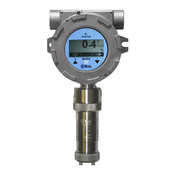
RAEGuard 2 PID has a graphic display and local sound alarm and light status indicator. A magnetic key interface enables the detector to be calibrated and operational parameters adjusted with the explosion- proof enclosure in place. - Page 8 RAEGuard 2 PID User’s Guide Applications: • Refineries, petrochemical and natural gas plants • Metallurgical • Chemical, medication • Environmental protection • Electricity, communications • Fire protection • Utilities • Pulp and paper, printing • Storage • Sewage disposal •...
-
Page 9: General Specifications
RAEGuard 2 PID User’s Guide General Specifications RAEGuard 2 PID Specifications Basic Parameters Principle PID (photoionization detector) Sensor Digital Smart Sensor Sampling Internal diaphragm pump Working Current DC 10 to 28V, 210mA at 24V Power <5W • 4-20mA • Three-level programmable alarm relays... -
Page 10: Proper Product Disposal At End Of Life
RAEGuard 2 PID User’s Guide RAEGuard 2 PID Specifications (continued) Physical Parameters Dimensions, 257 x 201 x 107 mm L x W x H (10.1" x 7.9" x 4.2") Material Stainless steel Weight 3.5 kg (7.7 lbs) Certification ATEX II 2G Ex d ia II CT4 Gb UL/CSA Class I, Div. -
Page 11: Operation
Prior to factory shipment, the RAEGuard 2 PID is calibrated and tested. However, the user should calibrate the instrument before the first use. -
Page 12: Physical Description
RAEGuard 2 PID User’s Guide Physical Description The RAEGuard 2 PID can be easily installed and integrated with various control systems. It is designed with flexible pipe- holding/wall-mounting options and standard connection terminals. Physical Dimensions The physical dimensions are as shown: 107mm (4.2") -
Page 13: Installation And Access Instructions
First, decide where the transmitter will be mounted. (Refer to installation drawing, below.) Drill two holes in mounting surface, with the center of the holes 5.25" (133mm) apart. Besides directly mounting the RAEGuard 2 PID to a wall, it can be mounted on a pipe. - Page 14 RAEGuard 2 PID User’s Guide Note: When installing the RAEGuard 2 PID, make sure the sensor is vertically oriented (pointing straight down). Wall Pole...
-
Page 15: Instrument Disassembly
RAEGuard 2 PID User’s Guide Instrument Disassembly Prior to service: Make sure power is OFF. Observe all Hazardous Location Safety procedures. 1. Loosen the fastening bolt 3. Tilt the instrument assembly before unscrewing the 90˚. housing lid. Unscrew the 4. Unlock the 24-pin connector housing lid from the housing on the ribbon cable. -
Page 16: Electrical Wiring
RAEGuard 2 PID User’s Guide To reassemble the instrument: Reconnect the 24-pin connector of the ribbon cable and lock it in place. Fasten the cable to the board. Mate the board with the clip on the left side and tilt it over. -
Page 17: Wiring Procedure
PC boards. Note: The terminal block plugs accept 12 AWG to 24 AWG wire. Lace the wires through the RAEGuard 2 PID’s wire hole(s) and connect wires to the corresponding pin numbers of the terminal... -
Page 18: Earth Grounding Instructions
RAEGuard 2 PID User’s Guide Earth Grounding Instructions 6.5.1 External Earth Grounding Fasten the crimped ground wire with hardware as illustrated below. The wire should have a minimum cross-section area of 4mm for its conductor. M4 Screw M4 Split washer... -
Page 19: Finished Grounding Wires
RAEGuard 2 PID User’s Guide 6.5.3 Finished Grounding Wires Internal and external grounding are shown here, as well as an alternate external grounding point. Always follow local electrical guidelines. Alternate External earth earth grounding grounding point Internal earth grounding Alarm Contact Setup The alarm contacts can drive external alarms such as a light or buzzer. - Page 20 RAEGuard 2 PID User’s Guide Three jumper blocks are located below the three green terminal blocks. They are labeled (from left to right): J4, J3, and J1. Here are their functions: Jumper Function High Error Jumper blocks Lift off the jumper for each one that you want to change and slide it back on, either connecting the middle and top points or middle and bottom points.
-
Page 21: Display And User Interface
RAEGuard 2 PID User’s Guide Display And User Interface User Interface The RAEGuard 2 PID’s user interface consists of a status LED, an LCD display, and three keys, [+], [MODE], and [-]. The three keys are operated by using the Magnet Key. -
Page 22: Using The Magnet Key
Using the magnet end of the Magnet Key, briefly touch the glass above the MODE circle or the triangles labeled [+] and [-]. Then remove the key straight out and away from the RAEGuard 2 PID. RAEGuard Magnet Key touching glass above the [+] triangle. -
Page 23: Instrument Status Display
RAEGuard 2 PID User’s Guide condition. If there are no errors or alarm conditions, the green “OK” LED is lit and the gas concentration is displayed. If there is an error, the “Fault” LED blinks and an error message blinks. Each alarm condition has a corresponding LED that blinks an amber color when the readings are outside a specified range or limit. -
Page 24: Navigating Settings
RAEGuard 2 PID User’s Guide Navigating Settings You can view the basic settings, clear the Peak and Minimum readings, and perform a test of the Analog system without entering Programming Mode. At the main reading screen, hold the magnetic key over [-] for two seconds. - Page 25 RAEGuard 2 PID User’s Guide • If you do not want to clear the minimum value, press [-]. • To clear the minimum value (reset it), press [+]. • If you do not want to clear the minimum value, press [-]. The screen advances to Min.
- Page 26 RAEGuard 2 PID User’s Guide Press [-] to advance to the screen showing the measurement range (M.Range) and high alarm (H.Alarm) and low alarm (L.Alarm) values: Press [-] to advance to the screen showing the firmware version and build time and date, and the serial number of the instrument: Press [-] to advance to the Analog Output Test screen.
- Page 27 RAEGuard 2 PID User’s Guide For example, if you have a sensor range of 0 to 1000 ppm, the detector LCD displays in sequence 0, 125, 250, 375…all the way up to 1000 ppm. These are the ppm equivalent values of 4,6, 8, 10, etc., all the way up to 20mA.
-
Page 28: Programming Menus
RAEGuard 2 PID User’s Guide Programming Menus Programming allows anyone with the password to change the instrument’s settings, calibrate the instrument, etc. Depending on whether you use the Basic or Advanced Mode, both of which have different passwords, you can access different menus and submenus. -
Page 29: Entering Programming Mode
RAEGuard 2 PID User’s Guide Entering Programming Mode Enter Programming Mode by using the magnetic key to press these buttons in sequence: 1. Press [+]. 2. Press [-]. 3. Press [MODE]. The password screen appears, with the cursor on the first digit: Input the 4-digit password: •... -
Page 30: Calibration
RAEGuard 2 PID User’s Guide As you repeatedly press [-], the selection moves from left to right, and you see these screens in sequence: Calibration Two types of calibration are available: Zero (fresh air) and Span. Note: Complete calibration procedures are detailed on page 39. - Page 31 RAEGuard 2 PID User’s Guide Zero/Fresh Calibration Your options are indicated along the bottom of the screen: • Press [+] to start. • Press [MODE] to quit and return to the menu. If you choose to start zero/fresh air calibration, you see this message: Please apply zero gas…...
-
Page 32: Measurement (Advanced Mode)
RAEGuard 2 PID User’s Guide • Gas Library is a library that consists of all the gases found in RAE Systems’ Technical Note TN-106 (available online at www.raesystems.com). • Press [-] to step between the two options. • Press [MODE] to go back to the menu level above it. - Page 33 4. Press [+] to save the Measurement Unit, [MODE] to return to editing it, and [-] to cancel the change. The new Measurement Unit is saved, and the RAEGuard 2 PID exits back to the “Monitor Setup” menu. Meas. Range (Advanced Mode) Each sensor head has a maximum range for its sensor (for instance, 100 ppm).
- Page 34 The RAEGuard PID can display concentrations of over 200 gases using the built-in library of correction factors. Refer to RAE Systems Technical Note TN-106, available online at www.raesystems.com, for further details. Measurement gases are organized in two lists: •...
- Page 35 RAEGuard 2 PID User’s Guide Then follow the steps for the type of selection group you have chosen: Last Ten 1. Step through the list’s gases by pressing [-]. 2. Register your selection by pressing [+]. 3. Save your choice by pressing [MODE].
-
Page 36: Alarm Setting
RAEGuard 2 PID User’s Guide Alarm Setting During each measurement period, the gas concentration is compared with the programmed high and low gas concentration alarm limits. If the concentration exceeds any of the preset limits, the alarms (and relays) are activated immediately to warn of the alarm condition. - Page 37 RAEGuard 2 PID User’s Guide Ext. Alarm Delay (Advanced Mode) In order to prevent false alarms, you can set a delay time between when an alarm event occurs and when the RAEGuard 2 sends out the alarm signal, up to 60 seconds. If the alarm duration is less than the alarm delay setting, then no relays will be triggered.
-
Page 38: Monitor Setup
50% to 100% (always on), and the period is 10 seconds. Therefore, a duty cycle of 60% means that the pump is on for 6 seconds and off for four seconds. RAE Systems’ patented duty cycling is employed by the instrument to clean the PID. A lower duty cycle has a greater effect on keeping the PID clean than a higher duty cycle. - Page 39 RAEGuard 2 PID User’s Guide measurement is greater than the 2ppm threshold and is re-enabled when the reading falls below 90% of the threshold (1.8 ppm). 1. Press [+] repeatedly to select a desired number. Numbers increase from 0 to 9. Once 9 is reached, pressing [+] again “wraps”...
- Page 40 RAEGuard 2 PID User’s Guide Pump Cycle(s) (Advanced Mode) This sets the length of time for one cycle of the pump running. 1. Press [+] repeatedly to select a desired number. Numbers increase from 0 to 9. Once 9 is reached, pressing [+] again “wraps”...
- Page 41 RAEGuard 2 PID User’s Guide Bus Baudrate Choose from three different baud rates for Modbus data transmission: 4800, 9600, or 19200. 1. Press [-] to place the cursor on the baud rate you want. 2. Press [+] to make the selection.
- Page 42 RAEGuard 2 PID User’s Guide Unit ID When using Modbus communication, you can give each RAEGuard 2 PID on a network a unique Unit ID that helps identify it. 1. Press [+] repeatedly to select a desired number. Numbers increase from 0 to 9. Once 9 is reached, pressing [+] again “wraps”...
- Page 43 3. Press [MODE] to register the selection. 4. Press [+] to save the new password, [MODE] to return to editing the password, and [-] to cancel the change. The new password is saved, and the RAEGuard 2 PID exits back to the “Monitor Setup” menu.
-
Page 44: Calibration
For maximum safety, the accuracy of the RAEGuard 2 PID should be checked by exposing the sensor to a known concentration calibration gas. The RAEGuard 2 PID is calibrated using a two-point calibration process. -
Page 45: Zero Calibration
RAEGuard 2 PID User’s Guide 10.1 Zero Calibration 1. Connect the zero gas cylinder to the gas inlet port on the RAEGuard2 PID using the provided calibration adapter. 2. In measurement mode, use the magnet key to press [+], [-], and then [MODE] in sequence. - Page 46 RAEGuard 2 PID User’s Guide 7. Press [+]. A countdown screen is shown as the calibration is performed: Note: You may abort the calibration during the countdown by pressing [-]. If you stop the calibration, the process stops and this screen is displayed before the menu screen is shown: 8.
-
Page 47: Span Calibration
Note: Make sure the labeled concentration of calibration gas matches the value that is set in the RAEGuard 2 PID. 2. If the RAEGuard 2 PID is not already in Programming Mode, use the magnet key to press [+], [-], and then [MODE] in sequence. - Page 48 RAEGuard 2 PID User’s Guide 6. Press [+], and this screen appears: 7. Start the gas flow. 8. Press [+]. A countdown screen is shown as the calibration is performed: Note: You may abort the calibration during the countdown by pressing [-].
-
Page 49: Alarm Signal Summary
RAEGuard 2 PID User’s Guide Alarm Signal Summary The following are reading-related alarms. Status Relay Status Analog Indication Output Normal Green Failure: Disable According Low alarm: Disable to Reading High alarm: Disable Value Low Alarm Failure: Disable According (2 flashes... -
Page 50: Maintenance
RAEGuard 2 PID User’s Guide Maintenance As a guide, it is recommended to regularly “bump test” a RAEGuard 2 PID unit with a known percentage gas. Also, periodically check the sensor inlet and outlet to make sure they are clean and unobstructed. -
Page 51: Appendix A: Range, Sensor And Related Configuration
RAEGuard 2 PID User’s Guide Appendix A: Range, Sensor and Related Configuration The following table shows the measurement range and related configurations for four different DigiPID sensor modules: Span Gas Default Alarm Setup (ppm) Sensor Resolution Setup (ppm) (ppm) Default... - Page 52 RAEGuard 2 PID User’s Guide 2. Data Structure/Communication Steps RAEGuard 2 PID only supports Function Code 0x03 (read-only registers). The detector only supports value reading. 0x03: Read-Only Register Requesting Message: Device Func- Register Register Quantity Quantity Address tion Address Address...
-
Page 53: Appendix B: Controlled Section
RAEGuard 2 And DigiPID 16.1 Scope The scope of this document is to describe the system aspects for use of the RAEGuard 2 PID by connection of the RAEGuard2 and DigiPID according to EN60079-25; UL913 and CAN/CSA-C22.2 No. 157-92 in hazardous locations. - Page 54 As demonstrated in the table above, RAEGuard 2 and DigiPID have matching entity parameters, which allows the two devices to be connected to form a single piece of equipment: RAEGuard 2 PID, with the resulting Ex specification given below, suitable for installation in hazardous areas defined by zones as Ex d ia IIC T4 Gb.
-
Page 55: Scope
RAEGuard 2 PID User’s Guide RAEGuard 2 16.3 Scope The scope of this document is to identify the section of the RAEGuard2 controlled part of manual. 16.4 Responsibility The included sections cannot be changed without prior approval from the Notified Body. - Page 56 RAEGuard 2 PID User’s Guide 1. Warnings And Directive Information - READ BEFORE OPERATING - This manual must be carefully read by all individuals who have or will have the responsibility of using, maintaining, or servicing this product. The product will perform as designed only if it is used, maintained, and serviced in accordance with the manufacturer’s instructions.
- Page 57 RAEGuard 2 PID User’s Guide 2. Marking Of RAEGuard 2 The RAEGuard 2 is certified according to ATEX and the IECEx schemes as protected by a flameproof enclosure provided one or two associated equipment output port protected as intrinsically safe [ia], one of which can include a set of flame arrestors for gas sampling.
- Page 58 RAEGuard 2 interface. The DigiPID sensor can be mounted on the on the RAEGuard 2 interface inside hazardous are in powered condition. This constellation is called RAEGuard 2 PID. 6. Connections And Ratings Outline drawing of the interface:...
- Page 59 The monitor should be calibrated for no less than every 6 months depending on use and exposure to gas and contamination. Calibration interval may very due to national legislation RAE Systems recommend the use of RAE Systems calibration gas Installation and Access Instructions •...
- Page 60 Always follow local electrical guidelines. Sensors are not interchangeable; use only RAE Systems sensors, and use only the sensor type specified for your RAEGuard2 monitor. Use of non-RAE Systems components will void the warranty and can compromise the safe performance of this product.
- Page 61 RAEGuard 2 PID User’s Guide 9. Physical Dimensions RAEGuard 2 can be easily installed and integrated with various control systems with its flexible pipe-holding/wall-mounting options and standard connection terminals. The physical dimensions are as follows: 112mm 130mm 118mm 187mm...
-
Page 62: Section 2: Digipid User's Guide
RAEGuard 2 PID User’s Guide SECTION 2: DigiPID User’s Guide... -
Page 63: Safety Instructions
Use only RAE Systems lamps and the sensor detector type specified for your module. Maintain by using only RAE Systems accessories, including a Teflon filter or UV shield. Use of non-RAE Systems components will void the warranty and can compromise the safe performance of this product. -
Page 64: Digipid Marking
RAEGuard 2 PID User’s Guide 17.1 DigiPID Marking The DigiPID is certified according to the IECEx scheme, ATEX and CSA for US and Canada as protected by intrinsic safety. The product is marked with the following information: RAE SYSTEMS 3775 N. 1 . -
Page 65: Operation Area And Conditions
RAEGuard 2 PID User’s Guide 17.2 Operation Area and Conditions 17.2.1 Hazardous Areas classified by Zones DIGI PID is intended to be used in hazardous areas or mines susceptible to fredamp classified zone 0, zone 1 or zone 2, within the temperature range of -40º... -
Page 66: Use In Hazardous Areas
RAEGuard 2 PID User’s Guide 17.4 Use In Hazardous Areas Equipment which is intended for use in explosive atmospheres and which has been assessed and certified according to international regulations may be used only under specified conditions. The components may not be modified in any way. -
Page 67: Specifications
RAEGuard 2 PID User’s Guide 17.6 Specifications Power Supply 5V ±0.25V DC Current 110 mA max Power Consumption < 0.6W Measuring Range 0 to 100 ppm, 1 to 1000 ppm Resolution 10 ppb, 100 ppb, 1 ppm (depends on model) -
Page 68: General Information
RAEGuard 2 PID User’s Guide General Information The DigiPID Sensor is a self-contained intelligent sensor module with built-in photoionization detector (PID) sensor processor, lamp driver, and analog and digital interface circuits. It is designed to detect volatile organic compounds (VOC) and has a standard external interface. -
Page 69: Grounding (Earth Connection)
RAEGuard 2 PID User’s Guide Control signal: This optional pole only delivers a high (3.3V) or low (0V) signal level. Caution: 6.2V is the maximum input voltage for all of the sensor module’s input poles. Grounding (Earth Connection) DigiPID includes a grounding connection via pin 6 of the 8-pin connector. -
Page 70: Physical Description
RAEGuard 2 PID User’s Guide Physical Description The DigiPID is a pumped sensor. The pump is in this version intended to pump the sample gas in though one of the DigiPID gas tubes and return it through the other. -
Page 71: Sensor Parts And Dimensions
RAEGuard 2 PID User’s Guide Sensor Parts And Dimensions DigiPID sensor shown with optional mounting adaptor Optional mounting adapter 8-pin interface connector Pump connections Sample inlet Sample outlet Optional mounting adapter PID Lamp Fastening nut Sensor module Teflon O-ring Sensor detector... -
Page 72: Operating The Sensor Module
RAEGuard 2 PID User’s Guide Operating the Sensor Module 22.1 Preparing The Sensor For Use Make sure the 8-pole input of the external intrinsically safe equipment matches the interface connector pinout configuration of the DigiPID. Make sure the input power supply range is between 4.75V and 5.25V DC, and the input current is about 200mA when the... -
Page 73: Using The Sensor Module
(0.5V to 2.5V) from pin 3 of the interface connector. The sensor module can be calibrated for different operations and gases. If the DigiPID sensor is connected to RAE Systems equipment, you can affix the sensor module directly to the equipment and then turn on the instrument’s power supply. -
Page 74: Sensor Module Calibration
RAEGuard 2 PID User’s Guide 23.2 Sensor Module Calibration The sensor module is calibrated before it leaves the factory. However, you can also calibrate the sensor module. Allow it to warm up for two hours before calibrating it. Calibration should be performed using external equipment, using a two-point calibration for the 100 and 1000 ppm VOC sensor. -
Page 75: Maintenance And Calibration
After inspection and/or replacement of parts, recalibrate the instrument. The lamp and sensor are not interchangeable with parts from other manufacturers; use only RAE Systems replacements. Use of non- RAE Systems components will void the warranty and can compromise the safe performance of this product. - Page 76 RAEGuard 2 PID User’s Guide Attachment ring Inlet/Outlet IMPORTANT! Align hole in filter with hole in top of PID sensor to Filter ensure unobstructed Sensor sample flow Module IMPORTANT! Only handle lamp PID Lamp by holding sides of end. Do not touch flat surface.
-
Page 77: Replacing The Sensor's Teflon Uv Shield
3. Take the old Sensor Module to your shop/service center to perform the rest of the activities, which will refresh the Sensor Module and make it ready as a replacement spare. Note: Teflon UV Shields are available from RAE Systems in packages of 10 (P/N: C01-2017-000). - Page 78 RAEGuard 2 PID User’s Guide 4. Unscrew and remove all four of the gold-plated contact “legs” from the Sensor Module. 5. Use a small flat-bladed screwdriver or similar tool to get between the Sensor Module and the Teflon UV Shield at the point nearest the shield’s large “notch,”...
- Page 79 RAEGuard 2 PID User’s Guide 8. Slide a new Teflon UV Shield over the contact “legs,” and gently press it down until it is snug against the surface of the Sensor Module. 9. Use your fingers to screw on the four contact “legs.”...
-
Page 80: Sensor & Lamp Cleaning/Replacement
RAEGuard 2 PID User’s Guide Sensor & Lamp Cleaning/Replacement Clean the PID sensor module, the lamp and housing only if: 1. The reading is inaccurate even after calibration. 2. The reading is very sensitive to air moisture. 3. A liquid has been sucked into the unit and damaged the unit. -
Page 81: Cleaning The Lamp Housing Or Changing The Lamp
RAEGuard 2 PID User’s Guide 25.2 Cleaning The Lamp Housing Or Changing The Lamp If the lamp does not turn on, the instrument will display an error message to indicate replacement of the lamp may be required. 1. If the lamp is operational, clean the lamp window surface and the lamp housing by wiping it with GC grade methanol using a cotton swab using moderate pressure. -
Page 82: Cleaning The Instrument
Occasional cleaning with a soft cloth is recommended. Do not use detergents or chemicals. 25.4 Ordering Replacement Parts If you need replacement parts, contact your local RAE Systems distributor. A list is available online: http://www.raesystems.com In the U.S., you can order sensors, replacement batteries, and other accessories online at: http://istore.raesystems.com/... -
Page 83: Electronic Waste Disposal
RAEGuard 2 PID User’s Guide Electronic Waste Disposal At the end of its life, this product must undergo separate collection and recycling from general or household waste. -
Page 84: Technical Support
RAEGuard 2 PID User’s Guide Technical Support To contact RAE Systems Technical Support: Monday through Friday, 7:00AM to 5:00PM Pacific (US) Time Phone (toll-free): +1 888-723-4800 Phone: +1 408-952-8461 Email: tech@raesystems.com RAE Systems Contacts RAE Systems by Honeywell World Headquarters 3775 N. - Page 85 RAEGuard 2 PID User’s Guide RAE Systems Europe ApS Kirstinehøj 23 A DK-2770 Kastrup Denmark Phone: +45 86 52 51 55 Fax: +45 86 52 51 77 orders@raeeurope.com sales@raeeurope.com service@raeeurope.com Web: www.raesystems.eu RAE Systems UK Ltd D5 Culham Innovation Centre...
- Page 86 RAEGuard 2 PID User’s Guide RAE BeNeLux BV Rijndal 20 2904 DC Capelle a/d IJssel Phone: +31 10 4426149 Fax: +31 10 4426148 Email: info@rae.nl Web: www.rae.nl RAE Systems Spain, s.l. Av. Remolar, 31 08820 El Prat de Llobregat Spain...
- Page 87 RAEGuard 2 PID User’s Guide RAE Systems Japan 403 Plaza Ochanomizu Bldg. 2-1 Surugadai Kanda Chiyoda-Ku Tokyo, Japan Phone: 81-3-5283-3268 Fax: 81-3-5283-3275 Email: jpsales@raesystems.com RAE Systems Korea #1010, DaeMyungAnsVill First, Sang-Dong 412-2, Wonmi-Gu, Bucheon, Kyungki-Do, Korea Phone: 82-32-328-7123 Fax: 82-32-328-7127...
-
Page 88: Product Registration
RAE Systems Europe Kirstinehøj 23A, DK-2770 Kastrup • Denmark Tel: +45.8652.5155 • Fax: +45.8652.5177 Web: www.raesystems.eu • Email: sales@raeeurope.com RAE Systems (Hong Kong) Ltd. Units 1516-18, 15/F, Delta House, 3 On Yiu Street Shatin, N.T. Hong Kong Web: www.raesystems.hk • Email: asiasales@raesystems.com Phone: +852.2669.0828...
Need help?
Do you have a question about the RAEGuard 2 PID and is the answer not in the manual?
Questions and answers